


6EXP
6EXP
INSTRUCTION MUNUAL
for Futaba 6EXP
6-channel,
PCM/PPM(FM) selectable
Radio control system
for Airplane/helicopter
1M23N12013
Futaba Corporation
Technical updates available at:
http://www.futaba-rc.com
Entire Contents © Copyright 2006

2
TABLE OF CONTENTS
Introduction ..........................................................................3
Service ..................................................................................3
Contents and specifications............................................... 4
Glossary................................................................................5
Introduction to the 6EXP system .......................................6
Transmitter controls and descriptions ..............................6
Radio installation .................................................................8
Receiver and servo connections .....................................10
Charging the Ni-Cd batteries ............................................11
LCD and Programming controls ......................................12
Programming the T6EXP radio .........................................14
MODL Model select function........................................14
MODL Model select function ..................................14
REST Data reset function .......................................14
ACRO/HELI Model type select function ................15
PULS Modulation select function ...........................15
TRNR Trainer function ............................................15
Model name settings............................................... 16
REVR Servo reversing ................................................. 16
D/R Dual Rate and Exponential settings .................. 16
D/R Dual Rate settings...........................................16
EXPO Exponentials ................................................17
EPA End Point Adjustments......................................... 17
TRIM Trim Settings ......................................................18
FS Fail safe (PCM mode only) .....................................30
(ACRO functions)
PMX1 Programmable Mixer #1....................................19
PMX2 Programmable Mixer #2 ...................................19
FLPR Flaperon mixing .................................................20
FLTR Flap trim..............................................................20
V-TL V-tail mixing .........................................................21
ELVN Elevon mixing.....................................................22
(HELI functions)
N-TH Normal Throttle Curve ........................................24
N-PI Normal Pitch Curve..............................................24
I-TH Idle-Up Throttle Curve function............................24
I-PI Idle-Up Pitch Curve function .................................25
HOLD Throttle hold function ........................................25
REVO Pitch - rudder mixing function ...........................26
GYRO Gyro mixing function.........................................26
SW-T Swash to throttle mixing.....................................28
SWSH Swashplate types selection & Swash AFR......28
Flow chart (ACRO) .............................................................31
Flow chart (HELI)................................................................32
OtherT6EXP functions.......................................................33
Trainer function .............................................................33
Throttle cut function......................................................33
Adjustable-length control sticks ...................................34
Changing the stick mode..............................................34
Flying safety guidelines ....................................................34
Flight preparation ..............................................................35
Model Data Recording Sheets (ACRO)............................36
Model Data Recording Sheets (HELI) .............................. 37
3
INTRODUCTION
Thank you for purchasing the Futaba 6EXP digital proportional R/C airplane/helicopter system. If this is your first “computer”
radio, rest assured that it is designed to make initial setup and field-tuning of your airplane/helicopter easier and more
accurate than would be if using a “non-computer” radio. Although this is a beginner or sport system with the requirements of
those flyers in mind, in order to make the best use of your Futaba 6EXP and to operate it safely, you must carefully read all
of the instructions.
Suggestion: If, while reading the instructions, you are unclear of some of the procedures or functions and become “stuck,”
continue to read on anyway. Often, the function or procedure will be explained again later in a different way providing another
perspective from which to understand it. Another suggestion is to connect the battery, switch and servos to the receiver and
actually operate the radio on your workbench as you make programming changes. Then, you’ll be able to see the effects of
your programming inputs.
SERVICE
(in USA)
If any difficulties are encountered while setting up or operating your system, please consult the instruction manual first.
For further assistance you may also refer to your hobby dealer, or contact the Futaba Service Center at the web site, fax
number or telephone number below:
www.futaba-rc.com
Fax: (217) 398-7721
Telephone (8:00 am to 5:00 pm Central time Monday through Friday): (217) 398-8970, extension 2
If unable to resolve the problem, pack the system in its original container with a note enclosed and a
thorough, accurate
description of the problem(s). Include the following in your note:
• Symptoms. • Any unusual mounting conditions.
• An inventory of items enclosed. • The items that require repair.
• Your name, address, and telephone number. • Include the warranty card if warranty service is requested.
Send your system to the authorized Futaba R/C Service Center at the address below:
Futaba Service Center
3002 N Apollo Drive Suite 1
Champaign, IL 61822
This product is to be used for sport and recreational flying of radio-control models only. Futaba is not
responsible for the results of use of this product by the customer or for any alteration of this product,
including modification or incorporation into other devices by third parties. Modification will void any
warranty and is done at the owner’s risk.
(USA only)
Protect the environment by disposing of rechargeable batteries responsibly. Throwing rechargeable
batteries into the trash or municipal waste system is illegal in some areas. Call 1-800-8-BATTERY for
information about Ni-Cd battery recycling in your area.

4
Transmitter: T6EXP
T6EXP Transmitter with 6-model memory.
Transmitting on 29, 35, 36, 40, 41, or 72 MHz band.
Operating system: 2-stick, 6-channel system
Modulation: FM(PPM) and PCM
Power supply: 9.6V NT8S600B Ni-Cd battery or 12V alkaline
battery
Current drain: 250mA
Receiver: R136F/R136HP/R137HP
R136F/R136HP/R137HP narrow band, FM/PCM/PCM 6/6/7
channel receiver.
Receiving on 29, 35, 36, 40, 41, or 72 MHz band.
Type: FM/PCM/PCM, Single conversion
Intermediate frequencies: 455kHz
Power requirement: 4.8V or 6V (shared with servo)
Current drain: 9.5mA (at no signal)
Size: 1.31x1.98x0.71” (33.4x50.3x18.1mm)
Weight: 0.98/0.99/0.99oz. (27.8/28.1/28.1g)
Receiver: R168DF/R168DP
R168DF/R168DP narrow band, FM/PCM 8 channel receiver.
Receiving on 29, 35, 36, 40, 41, or 72 MHz band.
Type: FM/PCM, Dual conversion
Intermediate frequencies: 455kHz, 10.7MHz
Power requirement: 4.8V or 6V (shared with servo)
Current drain: 10mA (at no signal)
Size: 2.20x1.14x0.79” (55.8x29.0x20.0mm)
Weight: 0.85/0.88oz. (24.0/25.0g)
Receiver: R156F
R156F narrow band, FM6 channel micro receiver.
Receiving on 29, 35, 36, 40, 41, or 72 MHz band.
Type: FM, Single conversion
Intermediate frequencies: 455kHz
Power requirement: 4.8V (shared with servo)
Current drain: 6mA (at no signal)
Size: 0.84x1.31x0.52” (21.4x33.3x13.1mm)
Weight: 0.4oz. (11.2g)
*The R156F receiver is designed to be used only for Park Flyers
and Slow Fly models. Due to the special design of the R156F, we
cannot recommend its use in other types of models (gas powered
models, etc.) that are flown at longer distances.
Receiver: R146iP
R146iP narrow band, PCM6 channel mini receiver.
Receiving on 29, 35, 36, 40, 41, or 72 MHz band.
Type: PCM, Single conversion
Intermediate frequencies: 455kHz
Power requirement: 4.8V (shared with servo)
Current drain: 6mA (at no signal)
Size: 1.13x1.68x0.63” (28.7x42.7x16mm)
Weight: 0.58oz. (16.5g)
CONTENTS AND SPECIFICATIONS
Servos: S3004/S3003
S3004 ball bearing/S3003 standard servo with mounting
hardware and servo arm assortment
Control system: Pulse width control,1.52ms neutral
Power requirement: 4.8 or 6V (from receiver)
Output torque: 44.4oz-in [3.2kg-cm] @4.8V
Operating speed: 0.23sec/60°@4.8V
Size: 1.59x0.78x1.41" [40.4x19.8x36mm]
Weight: S3004- 1.3oz (37.2g) / S3003- 1.3oz (38.0g)
Servos: S3001
S3001 standard ball bearing
Control system: Pulse width control,1.52ms neutral
Power requirement: 4.8 or 6V (from receiver)
Output torque: 44.4oz-in [3.2kg-cm] @4.8V
Operating speed: 0.23sec/60°@4.8V
Size: 1.59x0.78x1.41” [40.4x19.8x36mm]
Weight: S3004- 1.3oz (37.2g) / S3003- 1.3oz (38.0g)
Servos: S3110/S3114
S3110/S3114 micro servo
Control system: Pulse width control,1.52ms neutral
Power requirement: 4.8 (from receiver)
Output torque: 22.2oz-in [1.6kg-cm] @4.8V
Operating speed: 0.1sec/60°@4.8V
Size: 0.86x0.43x0.78” [21.8x11x19.8mm]
Weight: 0.27oz (7.7g)
Other components:
Switch harness
9"[200mm]aileron extension cord (to facilitate quick
connecting and disconnecting of aileron servo with removable
wing)
Instruction manual
*Specifications and ratings are subject to change without notice.
5
Receiver crystals:
The receiver frequency may be changed as long as it remains within the “low” and “high” band frequency range. If your
receiver is on any channel from 11 through 35, it is a “low band” receiver and the frequency may be changed to any other
channel from 11 through 35 without having to perform any other service. Simply purchase a crystal on the desired channel,
then replace the existing crystal in your receiver with the new one. If your receiver is on any channel from 36 through 60, it is a
“high band” receiver and the frequency may be changed to any other channel from 36 through 60. To order a receiver crystal,
replace the “**” in the order numbers below with the required channel number. (To order a receiver crystal on channel 30,
order FUTL5730.)
FM Dual Conversion 72 MHz low band (channels 11 - 35) receiver crystal . FUTL57**
FM Dual Conversion 72 MHz high band (channels 36 - 60) receiver crystal . FUTL58**
Note: Should you ever wish to change the transmitter frequency, the transmitter must be sent to the Futaba Service Center for retuning.
GLOSSARY
It will be helpful to understand the following terms before reading the rest of the manual. The terms are not in alphabetical
order, but are in a logical order that prepares the reader for understanding the next term.
Reversing (servo reversing) - A function that allows the user to determine the direction of response of each servo. If, after
hooking up the servos, a control on the model responds in the wrong direction, the user may change the servo's direction so
the control responds correctly.
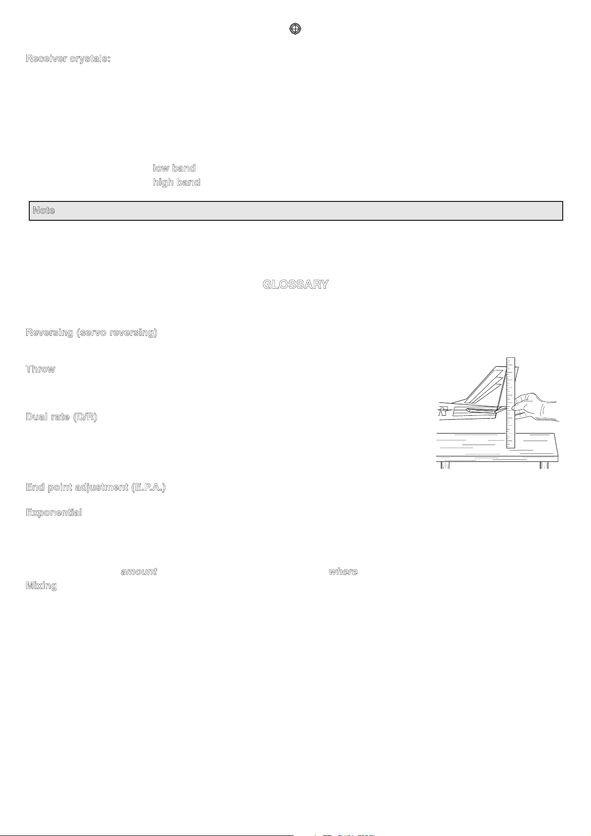
Throw - When speaking of a control surface (such as an elevator or aileron), the throw is the
distance the surface moves. Control surface throw is usually measured at the trailing edge of
the surface and is expressed in inches or millimeters. The model in the diagram has 1/2" [13mm]
of up elevator throw. Throw can also refer to the distance a servo arm (or wheel) travels.
Dual rate (D/R) - On the 6EXP the dual rate switch allows you to instantly switch, in flight,
between two different control throws for the aileron, elevator and rudder. Often, different control
throws are required for different types of flying. (“Low” throws may be required for flying at
high speeds where the model’s response becomes more sensitive, and “high” throws may be
required for aggressive aerobatic maneuvers or landing or flying at lower speeds where the
model's response becomes less sensitive.)
End point adjustment (E.P.A.) - Sets the overall, maximum distance the servo rotates in either direction. (No matter where
the dual rates are set, the servo will never travel beyond the limit set by the end point adjustment.)
Exponential - Normally, servos respond proportionally to control stick input from the transmitter (e.g., if the stick is moved
halfway, the servo will move halfway). However, with “exponential,” the servo can be made to move more or less than initial
stick movement (less servo movement is more common). Exponentials are commonly used to “soften,” or decrease initial
servo travel for the ailerons, elevators and rudder. This way, initial control stick inputs from the pilot result in small servo
movement for a smoother flying airplane.
(Dual rates adjust the
amount of servo travel. Exponentials determine where most of the travel will occur.)
Mixing - Two (or more) servos can be made to operate together either by mechanically joining the wires (with a Y-connector)
or by electronically “joining” them through programming functions in the transmitter. When servos are electronically joined via
programming, they are said to be “mixed.” Unlike joining servos with a Y-connector, when servos are mixed electronically they
can be made to move in opposition. Additionally, each servo’s end points can be independently set.
6
INTRODUCTION TO THE 6EXP SYSTEM
IMPORTANT!: Always turn on the transmitter first, then the receiver. When turning off the system, always turn off the receiver
first. The object is never to have the receiver on by itself. Otherwise, the servos or control surfaces could be damaged, or in the
case of electric-powered models, the motor may unexpectedly turn on causing severe injury.
IMPORTANT!: Never collapse the transmitter antenna by pushing down from the top. If one of the segments becomes
momentarily stuck you may damage the antenna. Instead, collapse the antenna from the bottom, drawing in one segment at a
time.
Transmitter
Transmits in both FM (PPM) and PCM by selecting modulation/cycling transmitter. Requires receiver of proper modulation. The
liquid-crystal display (LCD) on the face of the compact, ergonomically-designed case is easy to read and allows rapid data
input. The system also holds independent memories for six different models. The new, adjustable-length control sticks provide
an improved feel.
ACRO mode: External switches operate dual rates (D/R), landing gear, and trainer cord or “buddy-box” capabilities.
Programming features include servo reversing and E.P.A on all channels, dual rates, exponentials and programmable mixing.
Additionally, any one of four, factory-set, preprogrammed “wing-type” mixers including flaperon, V-tail, elevon mixing may be
selected.
HELI mode: Dual rate (D/R), Idle up, Throttle hold, and Gyro sense can be operates by switch. Two different gyro senses can
be set with Futaba GY401/502/611 Gyro on gyro function of this transmitter. Programming features include servo reversing
and E.P.A on all channels, dual rates, exponentials, throttle curve, pitch curve, throttle hold, and pit to rudder mixing(REVO).
Additionally, any one of three, factory-set, preprogrammed “swashplate type” mixers including three servo type 3-S/3-E may
be selected.
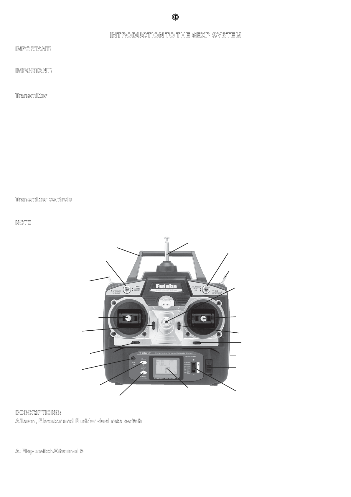
Transmitter controls
The diagram and explanations briefly describe the functions of the Futaba T6EXP transmitter. Full instructions on how to
operate the controls are provided beginning on page 14.
NOTE: The diagram shows a Mode 2 system as supplied. (More on flight modes on page 34).
Aileron, Elevator & Rudder
dual rate switch
Antenna
A:Gear switch/CH.5
H:Gyro switch/CH.5
A:Flap switch/CH.6
H:Throttle hold switch
Carrying handle
Liquid-crystal display
screen (LCD)
Throttle/rudder
control stick
(Mode 2)
MODE key
SELECT key
A:Tr ainer switch
H:Idle-up switch
Neck strap hook
Charging jack
On-off switch
Rudder trim
lever
Throttle trim
lever (Mode 2)
DATA INPUT lever
Aileron trim lever
Elevator trim lever
(Mode 2)
Aileron/elevator
control stick
(Mode 2)
Throttle cut
button
DESCRIPTIONS:
Aileron, Elevator and Rudder dual rate switch -
Use this switch to “flip” between two aileron, elevator and rudder control throw settings. The throws can be set up however you
prefer, but generally, when the switch is “up” the throws are greater (“high rate”) and when the switch is “down” the throws are
less (“low rate”). This switch also flips between exponential rates (if used).
A:Flap switch/Channel 6 - This switch operates the servo connected to channel 6 in the receiver if your model has flaps this
is the control used to operate them.
7
H:Throttle – hold switch - This switch operates to hold the engine in the idling position and disengaged it from the Throttle
Stick. It is commonly use to practice auto-rotation.
Neck strap hook - Mounting point for optional neck strap.
Aileron/elevator control stick - Operates the servos connected to channel 1 (aileron) and channel 2 (elevator) in the
receiver.
Trim levers (all) - Used to shift the neutral or center position of each servo as labeled in the diagram. Once either trim lever
is operated, the trim position is displayed on the LCD screen. Also once either edit key is operated, all trim positions are
displayed sequentially on the LCD screen.
NOTE: The throttle trim lever is intended for fine tuning the throttle servo when the engine is at idle. Throttle trim does not
affect the throttle servo when the throttle control stick is all the way up (so idle r.p.m. can be adjusted without affecting
throttle settings through the rest of the stick movement).
Charging jack - Port for charging the transmitter batteries with the included battery charger.
On/off switch
DATA INPUT lever - Used to change the values of the various functions displayed on the LCD screen
Liquid – crystal display screen (LCD) - Displays programming modes and values entered.
MODE key - Used to scroll through and display the “11-14” different functions.
SELECT key - Used to display the values for the current function.
Throttle – cut button - To use the throttle-cut function, lower the throttle stick all the way, then push the throttle-cut button to
fully close the carburetor and shut of the engine.
Throttle/rudder control stick - Operates the servos connected to channel 3 (throttle) and channel 4 (rudder) in the receiver.
A:Trainer switch - Operates the trainer functions. To operate as a trainer switch the transmitter must be connected to another
transmitter via. a trainer cord (available separately).
H:Idle – up switch - This switch operates to change the fight condition which is set the throttle curve and pitch curve of mid
air maneuvers (rolls, loops, stall turns) and 3D flight.
A:Retractable landing gear switch/Channel 5 - Switch operates the servo connected to channel 5 in the receiver if your
model has retractable landing gear this is the control used to extend and retract the gear.
H:Gyro switch/Channel 5 - You can connect the sense adjust connector to the channel 5 of the receiver to operate the gyro
which has two different sense. Also if you use Futaba GY401/502/611 Gyro, two different gyro senses setting on gyro function
in this transmitter can be call by this switch.
Antenna - Radiates signals to the receiver. Never fly a model without fully extending the antenna or you may create
interference to other modelers and decrease operational signal range of the transmitter. The antenna may be removed and
replaced with another in case it is inadvertently broken.
8
RADIO INSTALLATION
Follow these guidelines to properly mount the servos, receiver and battery.
INPORTANT!: Please use PCM receiver if the composition parts of the model used much metal, carbon graphite etc.
because they will generates quite a lot of the noise.
• Make certain the alignment tab on the battery, switch and servo connectors is oriented correctly and “keys” into the
corresponding notch in the receiver or connectors before plugging them in. When unplugging connectors, never pull on the
wires. Always pull on the plastic connector instead.
• If any servo wires are not long enough to reach the receiver, servo extension wires (available separately) may be used.
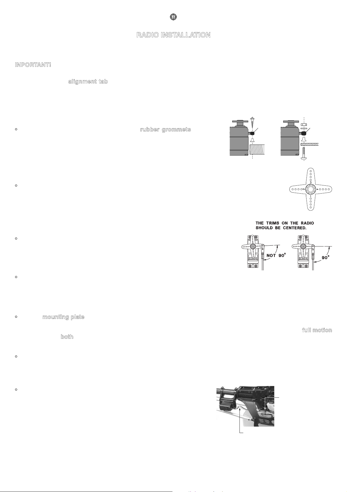
Servo
Rubber
grommet
Servo
Rubber
grommet
• Always mount the servos with the supplied rubber grommets. Do not over
tighten the screws. No part of the servo casing should contact the mounting
rails, servo tray or any other part of the airplane/helicopter structure. Otherwise,
vibration will be transmitted to the servo causing premature wear and/or servo
failure.
• Note the small numbers (1, 2, 3, 4) molded into each arm on the Futaba 4-arm servo arms. The numbers
indicate how many degrees each arm is “off” from 90 degrees to correct for minute manufacturing
deviations from servo to servo.
• To center the servos, connect them to the receiver and turn on the transmitter
and receiver. Center the trims on the transmitter, then find the arm that will be
perpendicular to the pushrod when placed on the servo.
• After the servos are installed, operate each servo over its full travel and check that the pushrods and servo arms do not
bind or contact each other. Also make sure the controls do not require excess force to operate. If there is an objectionable
buzzing sound coming from a servo, there is probably too much resistance in the control. Find and correct the problem.
Even if there is no servo damage, excess battery drain will result.
• Use the mounting plate from the receiver on/off switch as a template for the cutout and screw holes. Mount the switch on
the side of the fuselage opposite the engine exhaust, and where it won’t be inadvertently turned on or off during handling or
storage. Be certain the switch moves without restriction and “snaps” from ON to OFF, and that the cutout allows full motion
of the switch in both directions.
• When you install the switch harness to the helicopter, please use switch cover. Generally sandwich the frame by switch and
switch cover and securely tighten the screws. It might be different installations on model by model. In that case, please
follow the model instruction manual.
Fasten about 5-10cm
from the servo outlet
so that the lead wire
is neat.
Margin in the lead wire.
• To prevent the servo lead wires from being broken by vibration during flight,
provide a margin so that the wire sticks out slightly and fasten it at suitable
points. In addition, periodically check the wire during daily maintenance.
9
•
IMPORTANT: NEVER cut the receiver antenna or mount it in the model folded back on itself. Doing so will change its
electrical length, possibly reducing the distance from the pilot that the model can be controlled (“range”).
• The receiver antenna may be mounted inside or outside the model:
Internal antenna mounting:
• You may run the antenna inside of a non-metallic housing within the fuselage, but range may suffer if the antenna is
located near metal or carbon fiber pushrods or cables. Do not bind the antenna with servos, switch, battery harnesses. Be
sure to perform a range check before flying (see page 35).
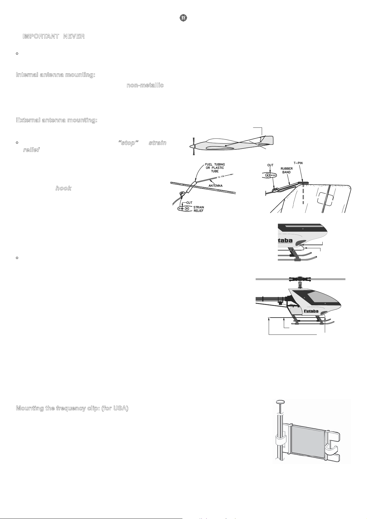
External antenna mounting:
Antenna
Rubber Band, etc.
A. B.
• A. Use a cut off servo arm as a “stop” or strain
relief inside the fuselage to keep tension off the
solder joint holding the antenna to the receiver.
Guide the antenna through a hole in the fuselage. (If
possible, insulate the hole with a rubber grommet or a
small piece of rubber tubing.)
B. Make a
hook from another cut off servo arm.
Insert the end of the antenna through two holes,
then connect the hook to a rubber band around a pin
inserted into the vertical stabilizer. Allow any excess
antenna length to trail behind the hook.
Antenna-exiting
hole
Rubber grommet or
silicon tube, etc.
Antenna
Nonmetal tube
• Please use rubber grommet or silicon tube to protect from cut or peel off insulation of
antenna on the fuselage antenna-exiting hole.
Place the receiver antenna out from the fuselage part to the nonmetal tube installed
in skid etc. Please keep antenna away from parts that made of metal and carbon
graphite.
• The receiver contains precision electronic parts. It is the most delicate radio component on-board the model and should
be protected from vibration, shock and temperature extremes. To protect the receiver, wrap it in R/C foam rubber or other
vibration-absorbing material. If appropriate, waterproof the receiver by placing it in a plastic bag and closing the open end
with a rubber band before wrapping it in foam. If moisture enters the receiver, intermittent operation or a failure may result.
Wrapping the receiver in a plastic bag also protects it from fuel and exhaust residue which, in some models, can work its
way into the fuselage.
Mounting the frequency clip: (for USA)
• To announce your frequency and avoid potential interference problems, the frequency
number should always be displayed on the transmitter antenna while flying. Peel the
backing from the numbers and apply them to both sides of the clip. Snap the end of the clip
that fits best to the base of the antenna as shown. You may cut off the other end of the clip.
10
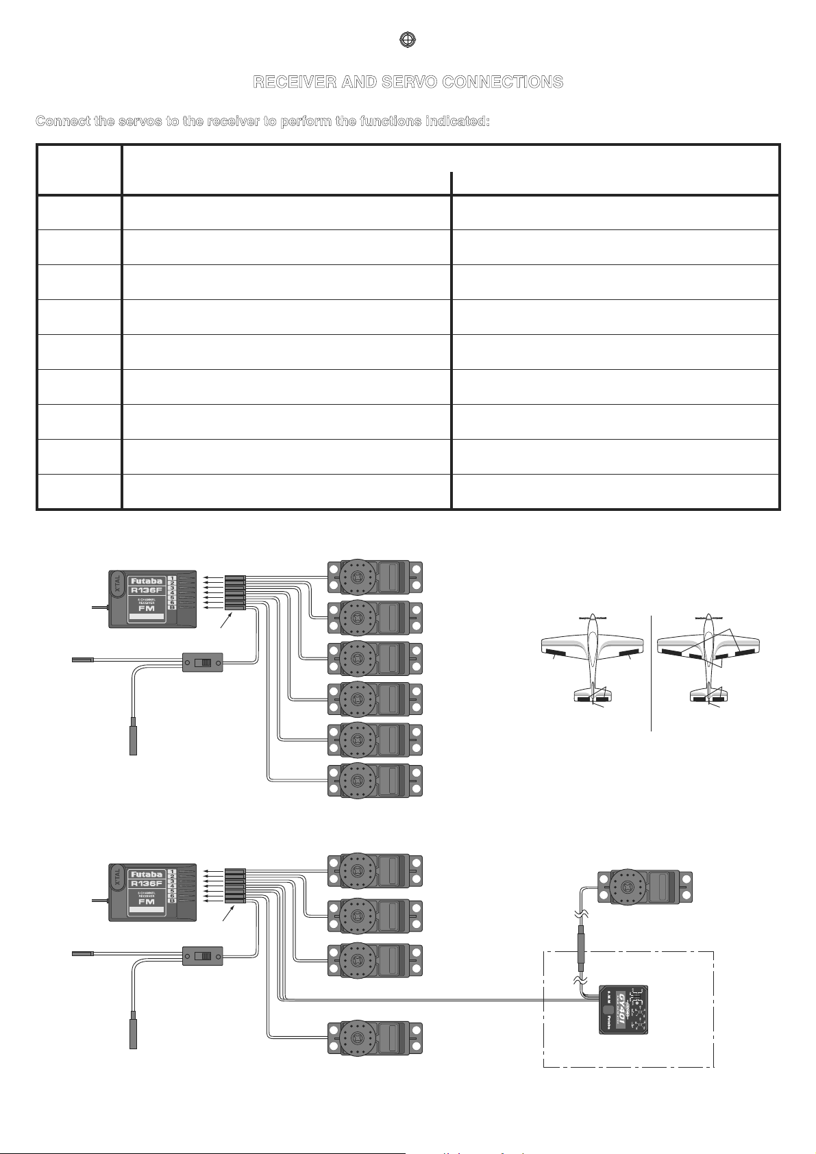
RECEIVER AND SERVO CONNECTIONS
Connect the servos to the receiver to perform the functions indicated:
Receiver
output
channel
Function
Aircraft (ACRO) Helicopter (HELI)
1
Aileron -or-right flaperon -or-right elevon (for tail-
less models)
Aileron
2
Elevator -or-left ruddervator (for V-tail models)
-or-left elevon (for tailless models)
Elevator
3 Throttle Throttle
4 Rudder -or-right ruddervator (for V-tail models) Rudder
5 Retractable landing gear Gyro sensitivity
6 Flap -or-left flaperon Pitch
7 Not used Not used
8 Not used Not used
B
Receiver on/off switch (the plug colored red
goes into the receiver)
Receiver on/off switch (the plug colored red
goes into the receiver)
Receiver
Switch
Harness
To Battery
Charging
Jack
(Black)
Aileron Servo
(CH1)
Optional
Gyro
System
Elevator Servo
(CH2)
Throttle Servo
(CH3)
Rudder Servo
Rudder (CH4)
Pitch Servo
(CH6)
The diagram shown is for helicopter models only. It is necessary to buy an additional gyro separately.
Gyro sensitivity (CH5)
Receiver
Switch
Harness
To Battery
Charging
Jack
(Black)
Aileron Servo
(CH1)
Elevator Servo
(CH2)
Throttle Servo
(CH3)
Rudder Servo
(CH4)
Gear Servo
(CH5)
Flap Servo
(CH6)
The diagram shown is for aircraft models only. Additional servos may have to be purchased separately.
(CH1)
(CH6)
(CH1)
(CH2)
(CH4)
(CH2)
(CH4)
Flaperon Mode (Dual Aileron
Servo, CH1 & 6)
Independent Aileron & Flap
(CH6)
(Red)
(Red)
11
CHARGING THE Ni-Cd BATTERIES
The transmitter and receiver batteries included with your 6EXP system are rechargeable, Ni-Cd (nickel-cadmium, pronounced
ni-kad) batteries. Ni-Cd batteries require special care and charging.
Read the charging instructions carefully.
NOTE: The batteries are supplied partially charged, but will require a full, overnight charge before the model may be flown.
1. Connect the transmitter charging cord coming from the A/C wall charger to the charge jack in the right side of the
transmitter case. The receiver charging cord may be connected to the batteries two different ways: The charge cord may be
connected directly to the battery pack, or to the vacant charge connector (black) coming from the on/off switch in the model.
Charging “through the switch” is preferred as there will be no need to disconnect the battery.
2. Plug the A/C wall charger into a wall outlet. Note: If the wall outlet can be turned off by a switch in the room, be certain the
switch remains on after leaving the room. Otherwise, the batteries will not be charged!
3. The LEDs (light-emitting diodes) should light red, indicating that current is flowing and the batteries are being charged.
Discharged batteries will take about 15 hours to fully charge. If using an aftermarket fast charger, be certain to follow
the manufacturer’s instructions provided with the charger so you do not overcharge the batteries. NEVER charge
the batteries at a rate higher than 1,000mAh. The batteries should also be discharged periodically to prevent a condition
called “memory.” If, for example, only two flights are made each time you go flying, the batteries will not have “reached”
very far down into their full capacity. After doing this several times the batteries will “remember” and eventually “think” they
can supply only enough power for two flights. After two flights the batteries may not provide enough power to operate the
system, thus causing a crash. To erase any potential memory, cycle the batteries by discharging, then charging them with a
commercial battery cycler, or leave the system on and exercise the servos by moving the transmitter sticks until the servos
are moving very slowly, indicating that the battery is discharged. Cycling should be done every one to two months, even
during the winter or periods of long storage. If using a cycler with a readout, note the capacity after the batteries have been
cycled. If there is a noticeable drop in capacity the batteries should be replaced.
Note: Charging your batteries with the included Futaba A/C battery charger is always safe. However, fast-charging with
an aftermarket charger is acceptable as long as you know how to properly operate the charger. NEVER charge at a rate
higher than 1,000 mAh (1 Amp). If not done correctly, fast-charging can damage the batteries.
12
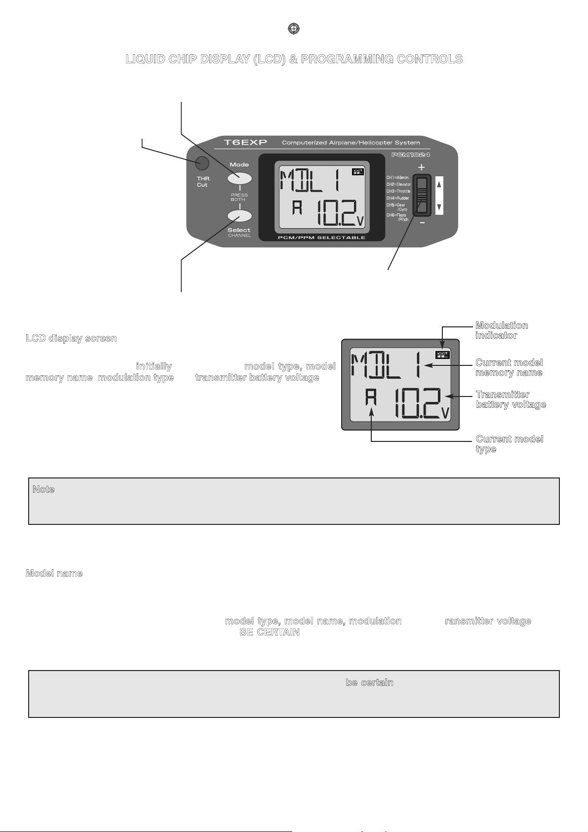
LIQUID CHIP DISPLAY (LCD) & PROGRAMMING CONTROLS
To open
programming menu;
Press both keys
simultaneously and
hold for one second
MODE key - use to select desired
function while programming
Throttle-cut button -
To use the throttle-cut
function,
SELECT key - use to select items within
function to be set or changed in the screen
DATA INPUT lever - use this lever to input
numbers or settings
LCD display screen
Current model
memory name
Modulation
indicator
Transmitter
battery voltage
Current model
type
When the transmitter is initially turned on, the model type, model
memory name, modulation type and transmitter battery voltage are
displayed on the LCD screen. When prompted by the user, the functions
and settings stored in the memory can also be read on the screen. The
user accesses the different functions using the MODE and SELECT
keys and changes the values and settings using the DATA INPUT lever.
(This is called programming!)
Note: Feel free to explore by scrolling through the programs and viewing the displays using the MODE and SELECT keys.
The MODE and SELECT keys only determine what will be displayed on the screen and will not change any of the settings.
Only when using the DATA INPUT lever will you be able to change any of the settings.
Model name
The Futaba T6EXP stores model memories for six models. This means all the data (control throws, trims, end points, etc.) for
up to six different models can be stored in the transmitter and activated at any time (depending upon which model you choose
to fly that day). This eliminates the requirement for reconfiguring the transmitter each time you decide to fly a different model
with it! When the transmitter is turned on the model type, model name, modulation and the transmitter voltage will be
indicated on the LCD screen. Before every flight BE CERTAIN that the correct model name for the model you intend to fly
appears on the screen. If the transmitter is not operating the correct model, some (or all) of the controls could be reversed and
the travels and trims will be wrong.
Flying a model with the wrong program will result in a crash, so always
be certain the model name in the transmitter is
correct. One way to ensure this is to write the corresponding model name directly on the airplane or helicopter, or attach a
list to the bottom or back of the transmitter.
 Loading...