


6-Channel Digital Proportional R/C System
 TM
TM
TM
INSTRUCTION MANUAL
1M23N30302

Technical updates and additional programming examples available at: http://www.futaba-rc.com/faq
Entire Contents © 2015

TABLE OF CONTENTS |
|
Introduction............................................ |
6 |
●Support and Service................................... |
6 |
●Application, Export, and Modification..... |
7 |
●Definitions of Symbols................................ |
9 |
●Precautions (do not operate without |
|
reading)....................................................... |
9 |
Before use.............................................. |
14 |
●Features .................................................... |
14 |
●Contents and technical specifications..... |
15 |
●System compatibilty................................. |
15 |
●Accessories................................................ |
16 |
●Transmitter controls................................. |
17 |
●Battery....................................................... |
19 |
●How to turn transmitter power ON/OFF..23 |
|
●Adjusting display contrast ...................... |
23 |
●Transmitter displays & buttons ............. |
24 |
●Keys lock .................................................. |
25 |
●Stick control ............................................. |
25 |
Stick control :Airplane example .................. |
26 |
Stick control : Helicopter example ............... |
27 |
Stick control : Multicopter example ............. |
28 |
●Digital trims ............................................. |
29 |
●Connector/Plug......................................... |
30 |
●Switch assignment table........................... |
31 |
●Receiver and servo connections.............. |
32 |
●Adjusting the length of the control sticks.. |
35 |
●Stick lever tension adjustment................ |
35 |
●Warning & error displays........................ |
36 |
●Link procedure......................................... |
37 |
●Receiver nomenclature............................ |
38 |
●R3006SB CH mode................................... |
39 |
●Receiver's antenna installation............... |
40 |
●Mounting the servo.................................. |
41 |
●Mounting the power switch..................... |
41 |
INTRODUCTION
BEFORE USE
COMMON
AIRPLANE
HELICOPTER
GLIDER
MULTICOPTER
TX SETTING
3

●Range check the radio.............................. |
42 |
●S.BUS/S.BUS2 Installation...................... |
43 |
●S.BUS Wiring example............................ |
44 |
●S.BUS2 System.......................................... |
45 |
●S.BUS/S.BUS2 Device setting.................. |
46 |
●Telemetry System..................................... |
47 |
Common function................................. |
48 |
●Model select............................................... |
50 |
Model select..................................................... |
51 |
RX type............................................................ |
51 |
Link.................................................................. |
51 |
Date reset......................................................... |
52 |
Model copy...................................................... |
52 |
●Model type................................................. |
53 |
Model type....................................................... |
54 |
Wing type......................................................... |
54 |
Tail type........................................................... |
54 |
Swash type....................................................... |
54 |
●Model name............................................... |
55 |
Model name..................................................... |
55 |
User name........................................................ |
56 |
●Fail safe..................................................... |
57 |
●End point................................................... |
59 |
●Trim........................................................... |
60 |
●Sub trim..................................................... |
61 |
●Servo reverse............................................. |
62 |
●Parameter.................................................. |
63 |
LCD contrast................................................... |
64 |
Back light......................................................... |
65 |
Light time........................................................ |
65 |
Light adjustment............................................. |
65 |
Battery alarm voltage .................................... |
65 |
Battery alarm voltage vibration ................... |
65 |
Buzzer tone...................................................... |
65 |
Home display................................................... |
66 |
Telemetry mode............................................... |
66 |
Telemetry unit................................................. |
66 |
Speech language.............................................. |
66 |
Speech volume................................................. |
67 |
Stick position alarm........................................ |
67 |
●Program mixing........................................ |
68 |
●AUX channel............................................. |
71 |
●Servo monitor Servo test.................... |
72 |
●Telemetry................................................... |
73 |
Telemetry:Rx-batt........................................... |
73 |
Telemetry:Ext-volt.......................................... |
77 |
Optional telemetry sensors............................. |
81 |
Telemetry:temp............................................... |
82 |
Telemetry:rpm................................................ |
83 |
Telemetry:altitude........................................... |
84 |
Telemetry:vario............................................... |
85 |
●Sensor........................................................ |
86 |
Sensor:register................................................ |
87 |
●S.BUS servo link....................................... |
88 |
●Model transfer.......................................... |
91 |
●Timer......................................................... |
92 |
●Trainer....................................................... |
94 |
Airplane function.................................. |
96 |
●Throttle cut............................................... |
98 |
●Dual rate EXPO................................. |
100 |
●Throttle curve......................................... |
102 |
●Idle down................................................. |
103 |
●Gyro sensor............................................. |
104 |
●Aileron Differential................................ |
105 |
●V-Tail....................................................... |
106 |
●Camber.................................................... |
107 |
●Air brake................................................. |
108 |
●Elevator→Flap mixing........................... |
110 |
●Flap→Elevator mixing........................... |
111 |
●Elevon...................................................... |
112 |
Helicopter function............................. |
113 |
●Condition................................................. |
115 |
●Throttle cut............................................. |
116 |
4

●Dual rate EXPO................................. |
118 |
●Trim offset............................................... |
120 |
●Delay........................................................ |
121 |
●Gyro sensor............................................. |
122 |
●SwashAFR.............................................. |
123 |
●Swash mixing.......................................... |
124 |
●Throttle curve......................................... |
126 |
●Pitch curve.............................................. |
128 |
●Revolution mixing (PIT to RUD).......... |
130 |
●Throttle hold........................................... |
132 |
●Hovering throttle.................................... |
133 |
●Hovering pitch........................................ |
134 |
Glider function.................................... |
135 |
●Condition................................................. |
137 |
●Dual rate EXPO................................. |
138 |
●Motor switch........................................... |
140 |
●Gyro sensor............................................. |
141 |
●Aileron Differential................................ |
142 |
●V-tail........................................................ |
143 |
●Butterfly mixing...................................... |
144 |
●Trim mix.................................................. |
145 |
●Elevator→Camber mixing.................... |
146 |
●Camber mixing....................................... |
148 |
●Aileron→Camber mixing...................... |
149 |
Multicopter function........................... |
150 |
●Flight mode............................................. |
152 |
●Center alarm........................................... |
153 |
●Dual rate EXPO................................. |
154 |
●Throttle curve......................................... |
156 |
●Throttle delay......................................... |
157 |
●Gyro sensor............................................. |
158 |
TX setting............................................ |
159 |
●Stick-mode.............................................. |
159 |
●Stick-adjustment.................................... |
159 |
●Throttle stick reverse............................. |
160 |
●Language................................................. |
160 |
5

Introduction
INTRODUCTION
Thank you for purchasing a Futaba® T-FHSS Air-2.4GHz 6K series digital proportional R/C system. This system is extremely versatile and may be used by beginners and pros alike. In order for you to make the best use of your system and to fly safely, please read this manual carefully. If you have any difficulties while using your system, please consult the manual, our online Frequently Asked Questions (on the web pages referenced below), your hobby dealer, or the
Futaba Service Center.
Due to unforeseen changes in production procedures, the information contained in this manual is subject to change without notice.
Support and Service: It is recommended to have your Futaba equipment serviced annually during your hobby’s “off season” to ensure safe operation.
IN NORTH AMERICA
Please feel free to contact the Futaba Service Center for assistance in operation, use and programming. Please be sure to regularly visit the 6K Frequently Asked Questions web site at www.futaba-rc.com/faq/. This page includes extensive programming, use, set up and safety information on the 6K radio system and is updated regularly. Any technical updates and US manual corrections will be available on this web page. If you do not find the answers to your questions there, please see the end of our F.A.Q. area for information on contacting us via email for the most rapid and convenient response.
Don’t have Internet access? Internet access is available at no charge at most public libraries, schools, and other public resources. We find internet support to be a fabulous reference for many modelers as items can be printed and saved for future reference, and can be accessed at any hour of the day, night, weekend or holiday. If you do not wish to access the internet for information, however, don’t worry. Our support teams are available Monday through Friday 8-5 Central time to assist you.
FOR SERVICE ONLY: |
FOR SUPPORT : |
Futaba Service Center |
(PROGRAMMING AND USER |
3002 N.Apollo Drive, Suite 1 |
QUESTIONS) |
Champaign, IL 61822 |
Please start here for answers to most questions: |
Phone: 217-398-0007 |
www.futaba-rc.com/faq/ |
www.futaba-rc.com/service.html |
Fax: 217-398-7721 |
Email: futabaservice@hobbico.com |
Phone: 217-398-8970 option 2 |
OUTSIDE NORTH AMERICA
Please contact your Futaba importer in your region of the world to assist you with any questions, problems or service needs.
Please recognize that all information in this manual, and all support availability, is based upon the systems sold in North America only. Products purchased elsewhere may vary. Always contact your region’s support center for assistance.
6

Application, Export, and Modification
1.This product may be used for model airplane or surface (boat, car, robot) use. It is not intended for use in any application other than the control of models for hobby and recreational purposes.
The product is subject to regulations of the Ministry of Radio/Telecommunications and is restricted under Japanese law to such purposes.
2.Exportation precautions:
(a) When this product is exported from the country of manufacture, its use is to be approved by |
|
the laws governing the country of destination which govern devices that emit radio frequencies. If |
Introduction |
been met. |
|
this product is then re-exported to other countries, it may be subject to restrictions on such export. |
|
Prior approval of the appropriate government authorities may be required. If you have purchased |
|
this product from an exporter outside your country, and not the authorized Futaba distributor in |
|
your country, please contact the seller immediately to determine if such export regulations have |
|
(b) Use of this product with other than models may be restricted by Export and Trade Control |
|
Regulations, and an application for export approval must be submitted. This equipment must not |
|
be utilized to operate equipment other than radio controlled models. |
|
3. Modification, adjustment, and replacement of parts: Futaba is not responsible for unauthorized |
|
modification, adjustment, and replacement of parts on this product. Any such changes may void |
|
the warranty. |
|
Compliance Information Statement (for U.S.A.)
This device, trade name Futaba Corporation, complies with part 15 of the FCC Rules. Operation is subject to the following two conditions:
(1)This device may not cause harmful interference, and
(2)This device must accept any interference received, including interference that may cause undesired operation.
(3)This module meets the requirements for a mobile device that may be used at separation distances of more than 20cm from human body.
To meet the RF exposure requirements of the FCC this device shall not be co-located with another transmitting device.
The responsible party of this device compliance is: Futaba Service Center
3002 NApollo Drive Suite 1, Champaign, IL 61822 U.S.A. TEL (217)398-8970 or E-mail: support@hobbico.com (Support)
TEL (217)398-0007 or E-mail: futabaservice@hobbico.com (Service)
The RBRC. SEAL on the nickel-cadmium battery contained in Futaba products
indicates that Futaba Corporation is voluntarily participating in an industry-wide
program to collect and recycle these batteries at the end of their useful lives, when
taken out of service within the United States. The RBRC. program provides a


 convenient alternative to placing used nickel-cadmium batteries into the trash or municipal waste system, which is illegal in some areas.
(for USA)
You may contact your local recycling center for information on where to return the spent battery.
Please call 1-800-8BATTERY for information on NiCd battery recycling in your area. Futaba
Corporation involvement in this program is part of its commitment to protecting our environment and conserving natural resources.
*RBRC is a trademark of the Rechargeable Battery Recycling Corporation.
7

Introduction
Federal Communications Commission Interference Statement (for U.S.A.)
This equipment has been tested and found to comply with the limits for a Class B digital device, pursuant to Part 15 of the FCC Rules. These limits are designed to provide reasonable protection against harmful interference in a residential installation.
This equipment generates, uses and can radiate radio frequency energy and, if not installed and used in accordance with the instructions, may cause harmful interference to radio communications. However, there is no guarantee that interference will not occur in a particular installation. If this equipment does cause harmful interference to radio or television reception, which can be determined by turning the equipment off and on, the user is encouraged to try to correct the interference by one or more of the following measures:
--Reorient or relocate the receiving antenna.
--Increase the separation between the equipment and receiver. --Consult the dealer or your Futaba Serivce center for help.
CAUTION:
To assure continued FCC compliance:
Any changes or modifications not expressly approved by the grantee of this device could void the user's authority to operate the equipment.
Exposure to Radio Frequency Radiation
To comply with FCC RF exposure compliance requirements, a separation distance of at least
20cm must be maintained between the antenna of this device and all persons.
This device must not be co-located or operating in conjunction with any other antenna or transmitter.
Where to Fly
We recommend that you fly at a recognized model airplane flying field. You can find model clubs and fields by asking your nearest hobby dealer, or in the US by contacting the Academy of ModelAeronautics.
You can also contact the national Academy of Model Aeronautics (AMA), which has more than 2,500 chartered clubs across the country. Through any one of them, instructor training programs and insured newcomer training are available. Contact the AMA at the address or tollfree phone number below.
Academy of Model Aeronautics
5161 East Memorial Drive
Muncie, IN 47302
Tele. (800) 435-9262
Fax (765) 289-4248
or via the Internet at http:\\www. modelaircraft.org
Always pay particular attention to the flying field’s rules, as well as the presence and location of spectators, the wind direction, and any obstacles on the field. Be very careful flying in areas near power lines, tall buildings, or communication facilities as there may be radio interference in their vicinity.
8

Precautions
Application, Export, and Modification Precautions.
1.This product is only designed for use with radio control models. Use of the product described in this instruction manual is limited to radio control models.
2.Export precautions:
a)When this product is exported, it cannot be used where prohibited by the laws governing radio waves of the destination country.
b)Use of this product with other than models may be restricted by Export and Trade Control Regulations.
3.Modification, adjustment, and parts replacement
Futaba is not responsible for unauthorized modification, adjustment, or replacement of parts on this product.
■No part of this manual may be reproduced in any form without prior permission.
■The contents of this manual are subject to change without prior notice.
■The contents of this manual should be complete, but if there are any unclear or missing parts please contact a Futaba Service Center.
■Futaba is not responsible for the use of this product by the customer.
■Company and product names in this manual are trademarks or registered trademarks of the respective company.
Forsafeuse
Please observe the following precautions to ensure safe use of this product at all times.
Meaning of Special Markings:
The parts of this manual indicated by the following marks require special attention from the standpoint of safety.
 DANGER - Procedures which may lead to dangerous conditions and cause death/serious injury if not carried out properly.
 WARNING - Procedures which may lead to a dangerous condition or cause death or serious injury to the user if not carried out properly, or procedures where the probability of superficial injury or physical damage is high.
 CAUTION - Procedures where the possibility of serious injury to the user is small, but there is a danger of injury, or physical damage, if not carried out properly.
= Prohibited |
= Mandatory |
WARNING: Alwayskeepelectricalcomponentsawayfromsmallchildren.
Flying Precautions
 WARNING
Never grasp the transmitter built-in antenna partwhileflying.
■ The transmitter output may drop drastically.
Always make sure that all transmitter stick movements operate all servos properly in the model prior to flight. Also, make sure that all switches, etc. function properly as well. If there are any difficulties, do not use the system until all inputsarefunctioningproperly.
 Neverflyintherangecheckmode.
■ In the dedicated range test range check mode, the transmitter output range is reduced and may cause a crash.
While operating, never touch the transmitter with, or bring the transmitter near, another transmitter,acellphone,orotherwirelessdevices.
■ Doing so may cause erroneous operation.
Introduction
9

Introduction
Never fly on a rainy day, when the wind is strong,andatnight.
■ Water could lead to failure or improper functionality and poor control of the aircraft which could lead to a crash.
Never turn the power switch on and off during flightorwhiletheengineormotorisrunning.
■ Operation will become impossible and the aircraft will crash. Even if the power switch is turned on, operation will not begin until transmitter and receiver internal processing is complete.
Donotstarttheengineormotorwhilewearing theneckstrap.
■ The neck strap may become entangled with the rotating propeller, rotor, etc. and cause a serious injury.
Do not fly when you are physically impaired as itcouldposeasafetyhazardtoyourselforothers.
 Donotflyatthefollowingplaces:
■Near another radio control flying field.
■Near or above people.
■Near homes, schools, hospitals or other places where people congregate.
■Near high voltage lines, high structures, or communication facilities.
When setting the transmitter on the ground duringflightpreparations,donotstanditupright.
■ The transmitter may tip over, the sticks may move and the propeller or rotor may rotate unexpectedly and cause injury.
Do not touch the engine, motor, or FET amp duringandimmediatelyafteruse.
■ These items may become hot during use.
For safety, fly so that the aircraft is visible at all times.
■ Flying behind buildings or other large structures will not only cause you to lose sight of the aircraft, but also degrade the RF link performance and cause loss of control.
From the standpoint of safety, always set the failsafefunction.
■ In particular, normally set the throttle channel to idle. For a helicopter, set the throttle channel to maintain a hover.
When flying, always return the transmitter setupscreentotheHomescreen.
■ Erroneous input during fllight is extremely dangerous.
Always check the remaining capacity of the transmitter and receiver batteries before each flyingsessionpriortoflight.
■ Low battery capacity will cause loss of control and a crash.
Alwayscheckoperation of each controlsurface and perform a range test before each flying session. Also, when using the trainer function, check the operation of both the teacher and studenttransmitter.
■ Even one transmitter setting or aircraft abnormality cause a crash.
 Beforeturningonthetransmitter:
1.Always move the transmitter throttle stick position to theminimum(idle)position.
2.Turnonthetransmitterfirstandthenthereceiver.
When turning off the transmitter's power switch. After the engine or motor has stopped (stateinwhichitwillnotrotateagain):
1.Turnoffthereceiverpowerswitch.
2.Thenturnoffthetransmitterpowerswitch.
■If the power switch is turned on/o in the opposite order, the propeller may rotate unexpectedly and cause a serious injury.
■Also always observe the above order when setting the fail safe function.
■Maximum low throttle: Direction in which the engine or motor runs at the slowest speed or stops.
When adjusting the transmitter, stop the engine except when necessary. In the case of a motor, disconnect the wiring and to allow it to continue operation. When doing so, please exercise extreme caution. Ensure that the aircraft is secured and that it will not come into contact with anything or anyone. Ensure that the motor will not rotate prior to making any adjustments.
■ Unexpected high speed rotation of the engine may cause a serious injury.
10
Battery and Charger Handling Precautions
 DANGER
Do not recharge a battery that is damaged, deteriorated,leakingelectrolyte,orwet.
Do not use the charger in applications other thanasintended.
Do not allow the charger or battery to become wet.
■ Do not use the charger, when it or your hands, are wet. Do not use the charger in humid places.
 Donotshortcircuitthebattery.
Do not solder or repair, deform, modify, or disassemblethebatteryand/orbatterycharger.
Do not drop the battery into a fire or bring it nearafire.
Do not charge and store the battery in direct sunlightorotherhotplaces.
Do not charge the battery if it is covered with anyobjectasitmaybecomeveryhot.
Do not use the battery in a combustible environment.
■ The gas ignite and cause an explosion or fiire.
Always charge the battery before each flying session.
■ If the battery goes dead during fllight, the aircraft will crash.
 WARNING
Do not touch the charger and battery for any lengthoftimeduringcharging.
■ Doing so may result burns.
Do not use a charger or battery that has been damaged.
Do not touch any of the internal components ofthecharger.
■ Doing so may cause electric shock or a burn.
If any abnormalities such as smoke or discoloration are noted with either the charger or the battery, remove the battery from the transmitter or charger and disconnect the power cordpluganddonotusethecharger.
■ Continued use may cause fire, combustion, generation of heat, or rupture.
Donotsubjectthebatteriestoimpact.
■ Doing so may cause fire, combustion, generation of heat, rupture, or liquid leakage.
Do not repeatedly charge a nickel-hydrogen batteryintheshallowdischargestate.
Charge the nickel-hydride battery with the dedicatedchargersuppliedwiththeset.
■ Charging the battery past the specified value may cause a fire, combustion, rupture, or liquid leakage. When quick charging, do not charge the battery above 1C.
■ Do not charge the battery while riding in a vehicle. Vibration will prevent normal charging.
When using the optional Li-Fe battery, disconnect the battery from the transmitter and charge it with the special LBC-4E5 Li-Fe Battery Chargersoldseparately.
When using the optional Li-Fe battery, do not connect the charger to the balance charge connector and the power connector at the same time.
■ Doing so cause a fiire, combustion, generation of heat, rupture, or liquid leakage.
Insert the power cord plug firmly into the receptacleuptoitsbase.
Always use the charger with the specified powersupplyvoltage.
■ Use the special charger by connecting it to a proper power outlet.
If the battery should get in your eyes, do not rub your eyes, but immediately wash them with tap water or other clean water and get treated by adoctor.
■ The liquid can cause blindness.
■ The battery memory effect will substantially shorten the battery life even if it is recharged.
Use and store the battery and battery charger inasecurelocationawayfromchildren.
■ Doing so may cause electric shock or injury.
If the battery leaks liquid or generates an abnormal odor, immediately move it to a safe placefordisposal.
■ Not doing so may cause combustion.
If the battery liquid gets on your skin or clothing, immediately flush the area with tap waterorothercleanwater.
■ Consult a doctor. The liquid can cause skin damage.
After the specified charging time has elapsed, endcharginganddisconnectthechargerfromthe receptacle.
When recycling or disposing of the battery, isolate the terminals by covering them with cellophanetape.
■ Short circuit of the terminals may cause combustion, generation of heat or rupture.
Introduction
11

Introduction
 CAUTION
Do not use the nickel-hydride battery with devicesotherthanthecorrespondingtransmitter.
Do not place heavy objects on top of the battery or charger. Also, do not place the battery orchargerinanylocationwhereitfall.
■ Doing so may cause damage or injury.
Do not store or use the battery and charger whereitisdustyorhumid.
■ Insert the power cord plug into the receptacle only after eliminating the dust.
After the transmitter has been used for a long time, the battery may become hot. Immediately removefromthetransmitter.
■ Not doing so may cause a burn.
Do not charge the battery in extreme temperatures.
■ Doing so will degrade the battery performance. An ambient temperature of 10 to 30 (50F to 86F) is ideal for charging.
 Unplugthechargerwhennotinuse.
Do not bend or pull the cord unreasonably and donotplaceheavyobjectsonthecord.
■ The power cord may be damaged and cause combustion, generation of heat, or electric shock.
Storage and Disposal Precautions
 WARNING
Keep wireless equipment, batteries, aircraft, etc.awayfromchildren.
 CAUTION
Do not store wireless devices in the following places:
Whereitisextremelyhot(40 [104F]orhigher) or cold(-10 [14F]orlower)
Wheretheequipmentwillbeexposedtodirect sunlight
WherethehumidityishighWherevibrationisprevalentWhereitisverydusty
Wherethedevicemaybeexposedtosteamand heat
When the device will not be used for a long time, remove the battery from the transmitter and aircraft and store them in a dry place where the temperature is between 0 and 30 [32F and 86F].
■ Left standing 'as is' may will cause battery deterioration, liquid leakage, etc.
Other Precautions
 CAUTION
Do not directly expose plastic parts to fuel, oil, exhaustgas,etc.
■If left in such an environment, the plastic may be attacked and damaged.
■Since the metal parts of the case may corrode, always keep them clean.
 JointheAcademyofModelAeronautics.
■ The Academy of Model Aeronautics (AMA) provides guidelines and liability protection should the need arise.
Always use genuine Futaba products such as transmitter,receiver,servo,FETamplifier,battery, etc.
■ Futaba is not responsible for damage sustained by combination with other than Futaba Genuine Parts. Use the parts specified in the instruction manual and catalog.
12

Introduction
13

use Before
BEFORE USE
 FEATURES
●T-FHSSAir-2.4G multi-function 6-channel transmitter
The Futaba 2.4GHz T-FHSS Air system is employed.
●Telemetry system
A T-FHSS Air bidirectional communication system is used. The voltage of the battery mounted in the fuselage can be displayed at the transmitter during flight. Altitude, temperature and R.P.M data can be displayed at the transmitter by installing various optional telemetry sensors in the fuselage.
●Speech function
Telemetry data can be listened to by plugging commercial earphones into the transmitter.
●Built-in antenna
Antenna built into the transmitter provides a simple appearance and improves handling ease.
●S.BUS/S.BUS2 servo setting function
S.BUS/S.BUS2 servo channel and various functions can be set by connecting the servo to the transmitter.
●Power-saving type transmitter
Four AA's alkaline batteries can be used. The optional HT5F1800B (NiMH 6.0V, 1800mA) or FT2F2100BV2 (lithium-ferrite 6.6V, 2100mA) battery can also be used.
●Vibration
Afunction that notifies the operator of various alarms by vibrating the transmitter can be selected.
●Unique model memory system
The transmitter body contains a 30 model memory.
●Mixing type selection
Fixed wing, helicopter, and glider mixing type can be selected to match the fuselage. In addition, 6 swash plate types can also be selected for helicopters. Multi-copter selection is also possible.
●Digital trim
Rapid trimming during flight is possible. The sound changes at the center of trim. The step size can be arbitrarily changed. The trim position is displayed on the LCD.
●Lever head length adjustment
The lever head length can be adjusted. Lever head shape that reduces slip during operation has been adopted.
●Switch/VR position change andAUX channel function change
Mixing and other switches and VR can be selected. Since the function of the AUX channels (5ch , 6ch) can also be changed, original mixing, in addition to existing mixing, can be created by using the programmable mixing function.
●Model data transfer function
Model data can be wirelessly transferred between 6K.
R3006SB receiver
●T-FHSSAir system S.BUS compatible
S.BUS output and conventional channel output are provided. S.BUS and conventional system sharing is possible.
●Battery fail safe function
14

 CONTENTS AND TECHNICAL SPECIFICATIONS
(Specifications and ratings are subject to change without notice.)
Your 6K includes the following components:
•T6K transmitter for airplanes or helicopters
•R3006SB Receiver
•Switch harness
*The set contents depend on the type of set.
Transmitter T6K
(2-stick, 6-channel, T-FHSSAir-2.4G system)
Transmitting frequency: 2.4GHz band
System: T-FHSSAir, S-FHSS, switchable Power supply: 6.0V Dry battery
Receiver R3006SB
(T-FHSSAir-2.4G system, dual antenna diversity, S.BUS, S.BUS2 system)
Power requirement: 4.8V~7.4V battery or regulated output from ESC, etc. (*1) Size: 1.7 x 0.98 x 0.35 in. (43.1 x 25.0 x 8.8 mm)
Weight: 0.3 oz. (8.5g)
Battery F/S Voltage: It sets up with a transmitter
(*1) When using ESC's make sure that the regulated output capacity meets your usage application.
 SYSTEM COMPATIBILITY
The 6K is a 2.4GHz T-FHSS Air system. The transmitter can also be switched to S-FHSS. (However, the telemetry system cannot be used with S-FHSS.) The usable receivers are shown below.
|
|
|
Communications System |
Usable Receivers |
|
T-FHSS Air |
R3006SB, R3008SB |
|
Default |
*R304SB, R304SB-E, T-FHSS surface system |
|
receivers do not operate. |
||
S-FHSS |
R2008SB |
|
R2006GS |
||
Change is possible |
||
R2106GF |
||
|
NOTE
*The Futaba T-FHSS Air system cannot be used with Futaba S-FHSS/FASST/FASSTest systems. Use it with a T-FHSS Air system transmitter and receiver. The T6K is a T-FHSS Air system, but can also
be used with an S-FHSS receiver by switching to S-FHSS. However, in this case the telemetry system
cannot be used.
*The T-FHSS Air system and T-FHSS surface system are different. The T6K cannot be used with the R304SB, R304SB-E or T-FHSS surface system receivers.
use Before
15

The following additional accessories are available from your dealer. Refer to a Futaba catalog for more information:
• HT5F1800B Transmitter battery pack - the (1800mAh) transmitter NiMH battery pack may be easily
|
exchanged with a fresh one to provide enough capacity for extended flying sessions. |
|
|
• FT2F2100BV2 Transmitter LiFe battery pack can also be used. However, charge with the charger only for |
|
|
LiFe. |
|
|
• Trainer cord - the optional training cord may be used to help a beginning pilot learn to fly easily by |
|
|
||
|
placing the instructor on a separate transmitter. Note that the T6K transmitter may be connected to another |
|
|
T6K system, as well as to any other models of Futaba transmitters. The T6K transmitter uses one of the |
|
|
three cord plug types according to the transmitter connected. (Refer to the description at the TRAINER |
|
|
function instructions). The part number of this cord is: FUTM4405. |
|
Before |
||
• Servos - there are various kinds of servos. Please choose the Futaba servos best suited for the model and |
||
|
||
use |
purpose you are using them for. If you utilize a S.BUS system, you should choose a S.BUS servo. |
|
• Telemetry sensor - please purchase an optional sensor, in order to utilize bidirectional communication |
||
|
||
|
system and to acquire the information from a model high up in the sky. |
|
|
[ Temperature sensor : SBS-01T/TE] [Altitude sensor : SBS-01A] [RPM sensor magnet type : SBS- |
|
|
01RM][RPM sensor optical type : SBS-01RO] [RPM sensor brushless motor type : SBS-01RB] |
|
|
• Neckstrap - a neckstrap can be connected to your T6K system to make it easier to handle and improve |
|
|
your flying precision since your hands won’t need to support the transmitter’s weight. |
|
|
• Y-harnesses, servo extensions, hub,etc - Genuine Futaba extensions and Y-harnesses, including a heavy- |
|
|
duty version with heavier wire, are available to aid in your larger model and other installations. |
|
|
• Gyros - a variety of genuine Futaba gyros is available for your aircraft or helicopter needs. |
|
|
• Receivers - various models of Futaba receivers may be purchased for use in other models. (Receivers for |
|
|
T-FHSSAir, S-FHSS types are available.) |
16

 TRANSMITTER CONTROLS - T6K
3 Position Switch (A)
3 Position Switch (C)
Built-in Antenna
Volume |
Carrying Handle
3 Position Switch (B)
2 Position Switch (D)
use Before
Rudder |
/Throttle |
Stick |
Power |
LED |
Throttle
Trim Lever
Rudder
Trim Lever
END Key |
Elevator |
/Aileron |
Stick |
Elevator Trim Lever
 Aileron Trim Lever
Key |
Key |
Jog Key |
Power Switch |
|
|
|
|
|
LCD Panel |
|
(Up position: ON) |
|
|
|
|
|
|
Hook |
(for optional neckstrap) |
17

 Multicopter/Robot specification
use Before
Throttle stick warning
Self neutral type Multicopter/Robot specification
A throttle stick returns neutrally by a spring.
Ratchet type General transmitter
A throttle stick doesn't return |
Throttle stick |
|
Motor or engine |
||
neutrally. |
||
|
power is controlled. |
 WARNING
You cannot use the throttle stick of self-neutral type for RC airplane, RC helicopter, and certain multi-copter.
It's very dangerous if Engine / Motor becomes middle-speed by self-return.
It's necessary to change the stick to the ratchet type if using it for RC airplane and RC helicopter.
18

 INSTALLATION AND REMOVAL OF THE T6K BATTERY
The T6K transmitter is designed to work with either four (4) AA alkaline dry cell batteries, or HT5F1800B battery pack, both available separately. The transmitter batteries used are a matter of personal preference. AAAlkaline batteries are available at any local hobby shop, grocery store, etc. A battery pack will need to be purchased from a hobby shop.
Battery Replacement Method
 Push
Push
Slide the battery the transmitter in the direction of the arrow in the figure.
Slide the battery cover back onto the case.
Battery Cover |
Load the new AA size |
batteries. Pay very close |
|
|
attention to the polarity |
|
markings and reinsert |
|
accordingly. |
Check:
Turn the power switch on the transmitter to the ON position. Check the battery voltage display on the LCD screen. If the voltage is low, check the batteries for insufficient contact in the case or incorrect battery polarity.
Disposal of the Dry Cell Batteries:
The method to dispose of used dry cell batteries depends on the area in which you reside. Dispose of the batteries in accordance with the regulations for your area.
 CAUTION
Always be sure you reinsert the batteries in the correct polarity order.
If the batteries are loaded incorrectly, the transmitter may be damaged.
When the transmitter will not be used for any short or long period of time, always remove the batteries. If the batteries do happen to leak, clean the battery case and contacts thoroughly. Make sure the contacts are free of corrosion.
use Before
19

When Using The Optional Battery HT5F1800B
When using an optional rechargeable battery, replace the battery as described below.
-Always use the optional HT5F1800B rechargeable battery. -The type of power source used must be set by system setting.
-When the transmitter will not be used for a long time, remove the battery.
use Before
Dry cell battery BOX
Disconnect the connector
Refer to the previous description and remove the transmitter battery cover.
After removing the dry cell battery box from the transmitter, disconnect the connector.
Insert the connector of the |
|
||
newbatteryandloadthenew |
|
||
battery into the transmitter. |
Finish by installing the |
||
|
|
battery cover. |
|
|
CAUTION |
||
|
|
When closing the battery |
|
|
|
cover, be careful that the |
|
Connect the battery |
|
battery cover does not pinch |
|
|
the battery lead wires. |
||
connector. |
|
||
Shorting of the battery lead wires may |
|||
|
|||
|
lead to fire and abnormal heating and |
||
|
cause burns or fire disaster. |
||
When Charging the Optional Battery HT5F1800B
Charging a NiMH Battery
(Example: When using the HT5F1800B with the special charger)
1 Plug the transmitter cord of the special charger into the charging jack on the rear of the transmitter.
2 Plug the charger into an AC outlet.
3 Check that the charging LED lights.
Charging jack
NiMH battery HT5F1800B (not included)
20
The charging time when charging the HT5F1800B battery with the optional special charger is approximately 15 hours.
However, when the battery has not been used for some time, repeat charging 2 or 3 times to activate the battery.
Over current protection
The transmitter charging circuit is equipped with an over current protection circuit (1.0A). If the battery is charged with a quick charger for other than digital proportional R/C sets, it may not be fully charged.
 AC outlet
Charger
 Transmitter
charging LED
 CAUTION
Never try to recharge a dry cell battery.
The transmitter may be damaged or the battery electrolyte may leak or the battery may break.
 Insert the batteries in the correct polarity.
If the polarity is incorrect, the transmitter may be damaged.
When the transmitter is not in use, remove the batteries.
If the battery electrolyte leaks, wipe off the case and contacts.
Do not use commercial AA size NiCd and NiMH batteries.
Quick charging may cause the battery contacts to overheat and damage the battery holder.
Charging A LiFe Battery
(Example: When using the FT2F1700BV2/2100BV2 with the special
charger)
1
2 Disconnect the battery from the T6K.
3 Balance charging cannot be done through the transmitter, you must remove the LiFe battery to do this charge.
To receiver |
To transmitter |
Ni-Cd battery |
charging jack |
Charging jack
Cannot be used for charge of LiFe.
Charge the optional FT2F1700BV2/2100BV2 (LiFe) battery with the special charger in accordance with the instruction manual supplied.
When the battery will not be used for a long time, to prevent it from deteriorating we recommend that it be kept in about the half capacity state instead of fully charged. Also be careful that the battery does not enter the over-discharged state due to self-discharge.
Periodically (about every 3 months) charge the battery.
Balance charging connector for

 LiFe battery charger.
LiFe battery is removed from transmitter.
use Before
21

CHARGING THE BATTERIES (When the rechargeable battery option is used)
Charging Your System’s Batteries
1.Connect the transmitter charging jack and batteries to the transmitter and receiver connectors of the charger.
2.Plug the charger into a wall socket.
3.Check that the charger LED lights.


 use Before
Charger
TX: Transmitter charging indicator RX: Receiver charging indicator
 To transmitter charging jack
Receiver battery
According to the description of the battery to be used and its exclusive charger, please use it after carrying out full charge.
We recommend charging the batteries with the charger supplied with your system. Note that the use of a fast charger may damage the batteries by overheating and dramatically reduce their lifetime.
When HT5F1800B is chosen, HBC-3A (4) is recommended.
When charging FT2F2100BV2, please make sure to remove the battery from the system to charge it. Charger for this battery is recommended to use LBC-
4E5.
Battery Care and Precautions
Below you will find some general rules and guidelines which should be adhered to when charging transmitter and/or receiver battery packs. These are included to serve only as general guidelines, and are not intended to replace or supersede the information provided by the battery and/or charger manufacturer. For complete information, please refer to the instructions that are included with the battery pack(s) and/or chargers that accompany the products purchased.
••Do not allow children to charge battery packs without adult supervision.
••Do not charge battery packs that have been damaged in any way. We strongly suggest frequent inspection of the battery packs to ensure that no damage has occurred.
••Do not to allow batteries to overheat! If overheated, disconnect the battery from the charger immediately and allow to cool.
••Do not mix cellsall cells should be of the same material, configuration, etc. ••Do not deep cycle NiMH batteries as permanent damage could result.
••Never charge batteries on a surface that may become hot, or may be impacted by the heat. ••Immediately end the charging procedure if either the batteries or charger itself become overly hot. ••NiMH cells do not exhibit the “memory effect” like NiCd cells, so little cycling is needed. Store NiMH packs with some voltage remaining on the cells (refer to battery supplier).
••NiMH cells have a self-discharge rate of approximately 20-25% (compared to 15% for NiCd batteries). It is important to recharge NiMH batteries immediately prior to use.
••Never connect the battery in reverse. Reverse connection will cause the battery to overheat or will damage the inside of the charger.
••Do not add an additional charge after charging.
••Never charge with a current exceeding the nominal capacity (lC) of the rechargeable battery. ••If a battery is charged with a current exceeding 1C, the battery will overheat and deteriorate.
••Do not connect two battery packs or more to one output terminal.
••Avoid extremely cold and hot places and the direct sunlight when you charge batteries.
••It is recommended to perform charging within the 10 ~ 30°C (50-86°F) range. Otherwise, it may cause abnormal charging and overheat.
22

 How to turn transmitter power ON/OFF
When turning on the power, the T6K transmitter will begin emitting RF automatically after it confirms the surrounding RF conditions. The status of the transmitter is displayed by LED at the upper part of the front of a T6K.
Power ON |
|
|
|
Power OFF |
||
Throttle Stick Slow |
Power Switch |
|||||
|
|
|
|
|
|
|
|
|
|
|
|
|
|
|
|
|
|
|
|
|
|
|
|
|
|
|
|
Power Switch
If the power switches are turned off in the opposite order the model may unexpectedly run out of control and cause a very dangerous situation.
Turning on the power switches
1.Turn on the transmitter power switch.
2.Turn on the receiver or speed control power switch.
ON ON 
Turning off the power switches
Always be sure the motor/engine is stopped.
1. Turn off the receiver or speed control power switch. 2. Then turn off the transmitter power switch.


 OFF OFF
 ADJUSTING DISPLAY CONTRAST
To adjust the display contrast, from the home menu press and hold the END BUTTON. |
||
Push the KEY while still holding the END BUTTON: |
|
|
KEY to brighten |
|
|
KEY to darken the display |
END |
|
Brighten
END |
|
Darken
use Before
23

 TRANSMITTER DISPLAYS & BUTTONS
When you first turn on your transmitter, a confirmation double beep sounds, and the screen shown below appears. Before flying, or even starting the engine, be sure that the model type and name appearing on the display matches the model that you are about to fly! If you are in the wrong model memory, servos may be reversed, and travels and trims will be wrong, potentially leading to a crash.
use Before
Model timer display <MDL>
Shows the cumulated ON time for each model. (hours:minutes)
System timer display <SYS>
Shows the cumulated ON time. (hours:minutes)
Resetting timers:
Select the desired timer with JOG KEY. The timer display flashes. To reset the timer, press JOG KEY.
Model number and name
Throttle trim display
END
Key
Each trim value
Rudder trim display
Pressandhold KEY forone secondtoopenprogramming menus.
Battery
voltage Telemetry Receiving accuracy
Elevator trim display
 key
key
Jog key
Aileron trim display
Edit buttons and Start-up Screen (appears when system is first turned on):
JOG KEY:
Control JOG KEY to scroll up/scroll down/scroll left/scroll right and select the option to edit within a function. When the menu has multiple pages, move the JOG KEY horizontally (left or right).
Press JOG KEY to select the actual function you wish to edit from the menu.
Press JOG KEY and hold one second to confirm major decisions, such as the decision to: select a different model from memory, copy one model memory over another, trim reset, store channel position in FailSafe, change model type, reset entire model, condition of a helicopter setup is changed.
An on screen inquiry will ask if you are sure. Press JOG KEY again to accept the change.
KEY:
Press and hold KEY for one second to open programming menus. It is used for changing a setup, or a numerical increase. Changing the menus pages can also be performed.
KEY:
It is used for change of a setup, or reduction of a number. Change of the page of a menu can also be performed.
END KEY:
Press END KEY to return to previous screen, close functions back to menus, and close menus to startup screen.
24

 Keys Lock
To prevent the data from being changed by erroneous touching of the keys during flight, a function which makes are keys impossible temporarily.
Keys Lock Display |
Press 1 second |
|
How to lock
1 The home screen is displayed.
2 Press the key and key simultaneously for about 1 second. "Key mark" is displayed and the keys disabled.
Lock : Jog key, key, key, END key
Press 1 second
How to unlock
1 Press the key and key simultaneously for about 1 second in the touch sensor locked state. The keys enabled again.
use Before
 Stick control
Elevator Stick
Pitching axis
Aileron stick Roll axis
Engine/motor |
Yawing axis |
Power |
|
Throttle stick |
Rudder stick |
|
*Example Stick Mode2 |
||
|
25

Stick control : Airplane Example |
*Example Stick Mode2 |
A general model example. (There is also a different operational model.)
use Before
|
RollaxisControl |
|
|
Rightroll |
|
|
The right aileron |
|
|
is to the up. |
|
The left aileron |
|
Aileronstick |
is in the down. |
|
To |
|
|
|
|
Levelflight |
|
|
|
Neutral |
Leftroll |
|
|
|
The right |
Aileronstick |
|
aileron is to |
|
The left aileron |
the down. |
Totheleft |
is in the up. |
|
|
 YawaxisControl
NoseRight 
|
Rudderstick |
|
|
Totheright |
|
|
A rudder is to |
|
|
the right. |
|
|
Neutral |
|
Straight |
A rudder is to |
|
|
the left. |
|
NoseLeft |
Rudderstick |
|
Totheleft |
||
|
PitchaxisControl
NoseUp
|
Elevatorstick |
|
|
UP |
|
|
(movedtothebottom) |
|
|
Elevator |
|
Levelflight |
up. |
|
|
||
|
Neutral |
|
|
Elevator is a |
|
|
down. |
|
NoseDown |
Elevatorstick |
|
DOWN |
||
|
||
|
(movedtothetop) |
ThrottleControl
Hight
Throttlestick
HIGHT
(movedtothetop)
Middle
Throttlestick
MIDDLE
(neutral)
Slow
 Throttlestick
SLOW
(movedtothebottom)
26

Stick control : Helicopter Example |
|
*Example Stick Mode2 |
|
A general model example. (There is also a different operational model.) |
|
||
|
RollaxisControl |
PitchaxisControl |
|
|
Rightroll |
NoseUp |
|
|
Aileronstick |
|
Elevatorstick |
|
|
|
|
|
To |
|
UP |
|
|
|
(movedtothebottom) |
|
Levelflight |
|
|
|
|
Levelflight |
|
|
Neutral |
|
Neutral |
Leftroll |
|
|
|
|
Aileronstick |
NoseDown |
Elevatorstick |
|
Totheleft |
DOWN |
|
|
|
|
(movedtothetop) |
NoseRight |
YawaxisControl |
Throttle/PitchControl |
|
use Before
|
Rudderstick |
Rise |
|
|
Throttlestick |
|
|
|
HIGHT |
||
|
Totheright |
|
|
|
|
|
|
PitchUp |
Hight |
(movedtothetop) |
|
|
|
Hovering |
|
|
Throttlestick |
|
Neutral |
|
|
|
|
|
|
|
|
MIDDLE |
|
|
|
|
|
Middle |
|
Straight |
|
Descent |
|
(neutral) |
|
|
PitchDown |
|
|
||
|
|
|
|
||
|
|
|
|
|
|
|
Rudderstick |
|
|
|
Throttlestick |
NoseLeft |
Totheleft |
|
|
Slow |
SLOW |
|
|
|
(movedtothebottom) |
27

Stick control : Multicopter Example |
*Example Stick Mode2 |
A general model example. (There is also a different operational model.) |
|
RollaxisControl |
PitchaxisControl |
use Before
Rightslide 


 Aileronstick
Totheright
Hovering
Levelflight
Neutral
Leftroll
Leftslide Aileronstick
Totheleft
YawaxisControl
NoseRight
Rudderstick
Totheright
 Hovering


 Levelflight
Neutral
NoseUp
|
Elevatorstick |
Backslide |
UP |
|
(movedtothebottom) |
Hovering |
|
Levelflight |
|
|
Neutral |
NoseDown
Frontslide |
Elevatorstick |
|
DOWN
(movedtothetop)
ThrottleControl
Rise


 Throttlestick
HIGHT
(movedtothetop)
Hovering
Throttlestick
MIDDLE
(neutral)
Descent
|
Rudderstick |
Stop |
Throttlestick |
|
NoseLeft |
Totheleft |
SLOW |
||
|
||||
|
|
|
(movedtothebottom) |
28

Digital Trims T1-T4 |
|
||
T4 |
T3 |
T2 |
T1 |
|
|
||
This transmitter is equipped with 4 digital trims.
Each time you press a trim button, the trim position moves one step. If you continue pressing it, the trim position starts to move faster. In addition, when the trim position returns to the center, the tone will change. You can always monitor trim positions by referencing the LCD screen.
*You can select the trim step amount and the display unit on the home screen on the T1-T4 setting screen within the linkage menu.
Note: The trim positions you have set will be stored in the non-volatile memory and will remain there.
use Before
Digital trim operational example
*Example Stick Mode2
Whenanairplanenoseupthoughan |
Whenanairplanenosedownthough |
elevatorstickisneutral. |
anelevatorstickisneutral. |
|
trimtodown |
Elevatortrimtoup |
|
|
|
Elevatorneutral |
|
Elevatorneutral |
|
|
Up |
It'sadjustedsothatitmayflylevelly.
29
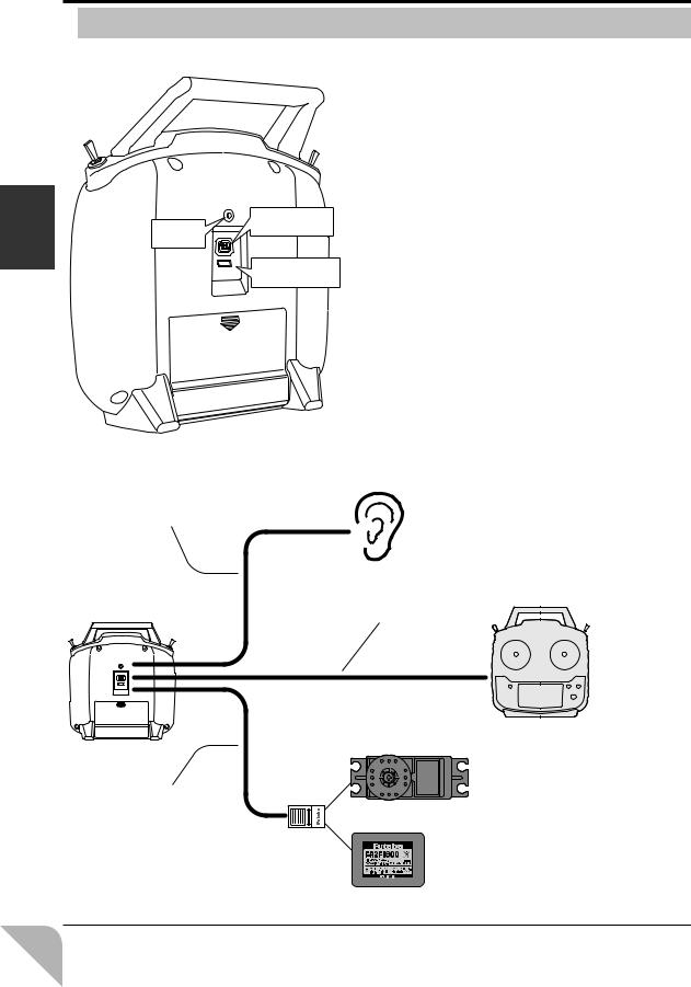
 CONNECTOR / PLUG
Earphone |
Trainer function |
connector |
|
plug |
|
use Before |
S.BUS |
connector (S.I/F) |
|
|
Earphone plug
The telemetry data can be listened to by plugging in commercial 3.5mm earphones. (See the telemetry item for the detailed setting.)
Trainer function connector
When you use the trainer function, connect the optional trainer cable between the transmitters for teacher and student.
*You can set the trainer function on the Trainer Function screen.
S.BUS connector (S.I/F)
When setting an S.BUS servo and telemetry sensor, connect them both here.
(Supply power by 3-way hub or 2-way cord.)
Earphone cable |
Telemetry data is heard |
|
|
|
Trainer cable |
|
Trainer system |
3-way hub or |
S.BUS servo setting |
2-way cord |
30
 Loading...