


Thank you for purchasing a Futaba 4PK-2.4GHz system.
Before using your 4PK-2.4GHz system, read this manual carefully in order to use your R/C set safely.
After reading this manual, store it in a safe place.
Application, Export, and Modification
1.This product may be used for models only. It is not intended for use in any application other than the control of models for hobby and recreational purposes.
2.Exportation precautions:
(a)When this product is exported from the country of manufacture, its use is to be approved by the laws governing the country of destination for devices that emit radio frequencies. If this product is then re-exported to other countries, it may be subject to restrictions on such export. Prior approval of the appropriate goverment authorities may be required. If you have purchased this product from an exporter outside your country, and not the authorized Futaba distributor in your country, please contact the seller immediately to determine if such export regulations have been met.
(b)Use of this product with other than models may be restricted by Export and Trade Control Regulations, and an application for export approval must be submitted.
3.Modification, adjustment, and replacement of parts: Futaba is not responsible for unauthorized modification, adjustment, and replacement of parts on this product. Any such changes may void the warranty.
Compliance Information Statement (for U.S.A.)
This device, trade name Futaba Corporation of America, model number R604FS, complies with part 15 of the FCC Rules. Operation is subject to the following two conditions:
(1)This device may not cause harmful interference.
(2)This device must accept any interference received, including interference that may cause undesired operation.
The responsible party of this device compliance is:
Futaba Service Center
3002 N Apollo Drive Suite 1, Champaign, IL 61822 U.S.A.
TEL (217)398-8970 or E-mail: support@futaba-rc.com (Support)
TEL (217)398-0007 or E-mail: service@futaba-rc.com (Service)
2

Battery Recycling (for U.S.A.)
The RBRC™ SEAL on the (easily removable) nickel-cadmium battery
and nickel-metal-hydride battery contained in Futaba products indicates
that Futaba Corporation of America is voluntarily participating in an in-


 dustry program to collect and recycle these batteries at the end of their useful lives, when taken out of service within the United States. The RBRC™ program provides a convenient alternative to placing used nickel-cadmium
batteries and nickel-metal-hydride batteries into the trash or municipal waste system, which is illegal in some areas.
You may contact your local recycling center for information on where to return the spent battery. Please call 1-800-8-BATTERY for information on Ni-Cd / Mi-MH battery recycling in your area. Futaba Corporation of America's involvement in this program is part of its commitment to protecting our environment and conserving natural resources.
NOTE: Our instruction manuals encourage our customers to return spent batteries to a local recycling center in order to keep a healthy environment.
RBRC™ is a trademark of the Rechargeable Battery Recycling Corporation.
ss.O PART OF THISTMANUAL MAY BEIREPRODUCED INAANYYFORM WITHOUT PRIORIPERMISSION ss4HEHCONTENTS OFTTHIS MANUALOARE SUBJECTSTO CHANGEUWITHOUTAPRIOR NOTICE
ss4HIS MANUALMHASNBEEN CAREFULLY WRITTEN N0LEASE WRITE TOL&UTABAAIF YOU FEELOTHAT ANYYCORRECTIONSEOR CLARIlCAtions should be made.
ss&UTABA ISANOTARESPONSIBLEOFOR THEEUSEPOF THISIPRODUCT
3

Table Of Contents |
|
For Your Safety As Well As That Of Others |
.........................8 |
Explanation of Symbols................................................................ |
8 |
2.4GHz System Precautions......................................................... |
8 |
High Speed Mode Precautions..................................................... |
8 |
Operation Precautions.................................................................. |
9 |
Ni-MH/Ni-Cd Battery Handling Precautions .............................. |
10 |
Storage and Disposal Precautions ............................................ |
11 |
Other Precautions ....................................................................... |
11 |
Before Using ...................................................................... |
12 |
Features ...................................................................................... |
12 |
Set Contents ............................................................................... |
14 |
TransmitterT4PK.......................................................................... |
15 |
T4PK Nomenclature................................................................. |
15 |
Power & Display Switch............................................................ |
16 |
Power Off Forgotten Alarm....................................................... |
16 |
High Voltage Alarm................................................................... |
16 |
Low Battery Alarm.................................................................... |
16 |
Digital Trim Operation............................................................... |
17 |
Grip Dial Operation .................................................................. |
17 |
Mechanical ATL Adjustment..................................................... |
18 |
Wheel & Trigger Tension Adjustment........................................ |
18 |
Trigger Slide Adjustment .......................................................... |
19 |
Ni-MH Battery Replacement .................................................... |
19 |
Charging The HT5F1700B Battery........................................... |
20 |
Grip Vibrator ............................................................................. |
21 |
Display when power switch turned on ...................................... |
21 |
Edit button lock and trim/dial lock............................................. |
22 |
Total Timer................................................................................ |
22 |
LCD Screen Contrast .............................................................. |
22 |
Changing wheel position and modifying for left-hand use........ |
23 |
Installing the accessory Hook .................................................. |
27 |
About Transmitter Antenna and Receiver ................................. |
28 |
About Transmitter Antenna....................................................... |
28 |
Receiver Nomenclature............................................................ |
28 |
How to link the transmitter and the receiver ............................. |
29 |
Receiver Installation ................................................................. |
29 |
Installation .......................................................................... |
31 |
Receiver and Servo Connections ............................................. |
31 |
Installation Safety Precautions .................................................. |
32 |
4

Initial Set-Up ....................................................................... |
35 |
Preparations (Transmitter).......................................................... |
35 |
Function Map ..................................................................... |
38 |
Menu Selection ........................................................................... |
38 |
Function Menu Screen ............................................................. |
38 |
Menu Screen............................................................................ |
39 |
Custom Menu........................................................................... |
40 |
Direct Selection ........................................................................... |
42 |
List of functions by menu type.................................................. |
44 |
Functions List ........................................................................... |
45 |
Functions ........................................................................... |
46 |
Receiver Type/Servo Response Mode "RXSYS"...................... |
46 |
Receiver type (C1/C2), Servo response (HIGH/NORMAL) select |
|
Servo Reverse "REV".................................................................. |
47 |
Servo operation reversing |
|
Subtrim "SUBTR" ....................................................................... |
48 |
Servo center position fine adjustment |
|
End Point Adjuster "EPA".......................................................... |
49 |
End point adjustment |
|
Throttle Acceleration "ACCEL"................................................. |
52 |
Function which adjusts the movement characteristic from the throttle neutral position |
|
Fail Safe/Battery Fail Safe Function "F/S" ............................... |
54 |
Fail safe, battery fail safe |
|
Steering Exponential "STEXP" ................................................. |
56 |
Steering operation curve adjustment |
|
Throttle Exponential "THEXP" .................................................. |
57 |
Throttle curve adjustment |
|
Steering Speed "STSPD"........................................................... |
61 |
Steering servo delay |
|
Throttle Speed "THSPD"............................................................ |
63 |
Throttle servo delay |
|
Start Function / Engine Cut "START" ....................................... |
66 |
Throttle preset at start function/ engine cut off by switch |
|
A.B.S. Function "A.B.S"............................................................. |
69 |
Pulse brake |
|
Brake Mixing "BRAKE".............................................................. |
74 |
Front and rear independent brake control for 1/5GP car, etc. |
|
For Your Safty
As Well As
That Of Others
Before
Using
Installation
Initial
Set-Up
Function
Map
Functions
Reference
5

Boat Mode "BOAT" ..................................................................... |
78 |
Boat, etc. brake operation stop/outboard engine tilt mixing |
|
Throttle Mode "THMOD" ............................................................ |
80 |
Neutral brake function |
|
Throttle servo forward and brake operation proportion setting |
|
Idle-Up "IDLUP" .......................................................................... |
82 |
Idle up at engine start |
|
Programmable Mixes 1/2 "PMIX1,2" ......................................... |
83 |
Programmable mixes between arbitrary channels |
|
Function Select Switch "SWTCH" ............................................ |
86 |
Selection of functions operated by push switches |
|
Function Select Dial "DIAL" ...................................................... |
88 |
Selection of functions operated by digital dial and digital trim |
|
Timer Function "TIMER"............................................................ |
90 |
Up, Fuel down, lap, or lap navigation timer |
|
Lap List "LAP-L"......................................................................... |
97 |
Lap timer data (lap time, average lap time) check |
|
Model Select "M-SEL"................................................................ |
98 |
Model memory call |
|
Model Name "NAME" ................................................................. |
99 |
Model memory name set/modify, username set/modify |
|
Model Copy "M-COP"................................................................ |
100 |
Model memory copy |
|
Model Reset "M-RES" .............................................................. |
102 |
Model memory reset |
|
Menu Type Select ...................................................................... |
103 |
Function menu type selection |
|
ESC Link Function "MCLNK" .................................................. |
104 |
Special function, Futaba ESC (MC850C, MC601C, MC401CR) |
|
System Functions "SYSTM" .................................................... |
108 |
Battery type setting |
|
Liquid crystal screen backlighting display mode setup |
|
Setting of ON time |
|
Liquid crystal screen contrast adjustment |
|
Buzzer sound tone adjustment |
|
Pilot lamp display color setup |
|
Initial screen display mode setting |
|
Second condition setting |
|
The power off forgotten alarm setting |
|
2.4GHz band setting |
|
About Second condition function |
|
6

Data Transfer "DTTRN" ............................................................ |
112 |
The T4PK model memory data to another T4PK |
|
Adjuster "ADJST"...................................................................... |
114 |
Steering wheel and throttle trigger correction |
|
Vibrator Function "VIBRA"...................................................... |
116 |
Vibrator setting |
|
Steerind Dual Rate "D/R"......................................................... |
117 |
Steering angle adjustment while running (dual rate) |
|
ATL Function "ATL".................................................................. |
118 |
Brake side adjustment |
|
Channel 3/4 Position "CH3","CH4" ......................................... |
119 |
Channel 3/4 servo operation position set/check |
|
Servo View "SERVO" ................................................................ |
120 |
Displays servo operation on a bar graph |
|
Reference ......................................................................... |
121 |
Ratings ...................................................................................... |
121 |
Optional Parts ........................................................................... |
122 |
Warning Displays ..................................................................... |
124 |
When requesting repair (For U.S.A.)........................................ |
126 |
For Your Safty
As Well As
That Of Others
Before
Using
Installation
Initial
Set-Up
Function
Map
Functions
Reference
7

Others Of That As Well As Safety Your For
For Your Safety As Well As That Of Others
Use this product in a safe manner. Please observe the following safety precautions at all times.
Explanation of Symbols
The parts of this manual indicated by the following symbols are extremely important and must be observed.
|
Symbols |
|
Explanation |
||
|
|
|
|
||
|
Danger |
cause death or serious injury if ignored and not performed properly. |
|||
|
|
Indicates a procedure which could lead to a dangerous situation and may |
|||
|
|
|
|
|
|
|
Warning |
Indicates procedures which may lead to dangerous situations and could |
|||
|
cause death or serious injury as well as superficial injury and physical |
||||
|
|
damage. |
|
|
|
|
|
|
|
|
|
|
Caution |
Indicates procedures that may not cause serious injury, but could lead to |
|||
|
physical damage. |
|
|
|
|
|
Symbols: |
: Prohibited |
: Mandatory |
||
2.4GHz System Precautions
Warning
Special attention should be paid before turning on the system while other cars are running or other airplanes are flying because the 2.4GHz RC system could potentially affect them.
Be sure to set the Fail Safe function.
High Speed Mode Precautions
Caution
When using the T4PK in the high speed (HIGH SPEED) mode, always use it under the following conditions:
Servos |
:6V Futaba digital servo (including BLS Series brushless servos) |
Receiver’s battery |
:6V Ni-Cd battery |
Transmitter mode |
:HIGH SPEED mode (See p.46 for setting method.) |
|
|
Under other conditions, the set will not operate, or the specified performance will not be displayed even if it operates. In addition, it may cause servo trouble. Futaba will not be responsible for damage, etc. caused by combination with the products of other companies.
In addition, the FSU1 Fail Safe Unit cannot be used because the system is different. Use the fail safe function of the transmitter.
When using analog servos, always switch the T4PK servo response to the NORMAL mode.
Transmitter mode |
:NORMAL mode (See p.46 for setting method.) |
Receiver’s battery |
:6V Ni-Cd battery |
|
|
The set cannot operate in the HIGH SPEED mode. Operation in this mode will cause trouble of servo and other equipments. Digital servos (including BLS Series brushless servos) can also be used in the NORMAL mode.
8

Operation Precautions
Warning
Do not operate outdoors on rainy days, run through puddles of water or use when visibility is limited.
Should any type of moisture (water or snow) enter any component of the system, erratic opreation and loss of control may occur.
Do not operate in the following places.
-Near other sites where other radio control activity may occur. -Near people or roads.
-On any pond when row boats are present.
-Near high tension power lines or communication broadcasting antennas.
Interference could cause loss of control. Improper installation of your Radio Control System in your model could result in serious injury.
Do not operate this R/C system when you are tired, not feeling well or under the influence of alcohol or drugs.
Your judgment is impaired and could result in a dangerous situation that may cause serious injury to yourself as well as others.
Extend the transmitter antenna to its full length.
If the transmitter antenna is not fully extended, the operating range of the radio will be reduced.
Always perform a operating range check prior to use.
Problems with the radio control system as well as improper installation in a model could cause loss of control.
(Simple range test method)
Have a friend hold the model, or clamp it down or place it where the wheels or prop cannot come in contact with any object. Walk away and check to see if the servos follow the movement of the controls on the transmitter. Should you notice any abnormal operation, do not operate the model. Also check to be sure the model memory matches the model in use.
Check the transmitter antenna to be sure it is not loose.
If the transmitter antenna works loose, or is disconnected while the model is running, signal transmission will be lost. This will cause you to lose control of the model. Rotate the antenna softly with your fingers when checking whether it is loosely or firmly fixed. Do not screw the antenna forcibly. Otherwise its antenna-holding part can be damaged.
Caution
Do not touch the engine, motor, speed control or any part of the model that will generate heat while the model is operating or immediately after its use.
These parts may be very hot and can cause serious burns.
Turning on the power switches.
Always check the throttle trigger on the transmitter to be sure it is at the neutral position.
1.Turn on the transmitter power switch.
2.Turn on the receiver or speed control power switch.
Turning off the power switches
Always be sure the engine is not running or the motor is stopped.
1.Turn off the receiver or speed control power switch.
2.Then turn off the transmitter power switch.
If the power switches are turned off in the opposite order, the model may unexpectedly run out of control and cause a very dangerous situation.
For Your Safety As Well As That Of Others
9

Others Of That As Well As Safety Your For
When making adjustments to the model, do so with the engine not running or the motor disconnected.
You may unexpectedly lose control and create a dangerous situation.
(Fail safe function)
Before running (cruising), check the fail safe function.
Check Method; Before starting the engine, check the fail safe function as follows:
1)Turn on the transmitter and receiver power switches.
2)Wait at least one minute, then turn off the transmitter power switch. (The transmitter automatically transfers the fail safe data to the receiver every minute.)
3)Check if the fail safe function moves the servos to the preset position when reception fails.
The fail safe function is a safety feature that minimizes set damage by moving the servos to a preset position when reception fails. However, if set to a dangerous position, it has the opposite effect. When the reverse function was used to change the operating direction of a servo, the fail safe function must be reset.
Setting example: Throttle idle or brake position
Ni-MH / Ni-Cd Battery Handling Precautions
(Only when Ni-MH/Ni-Cd batteries are used)
Warning
Never plug the charger into an outlet other than indicated voltage.
Plugging the charger into the wrong outlet may result in an explosion, sparking, or fire.
Never insert or remove the charger while your hands are wet.
You may get an electric shock.
Do not use the transmitter's battery, HT5F1700B, as the receiver's battery.
Since the transmitter's battery has an overload protection circuit, the output power will be shut down when the high current load is applied. This may result in run-a-way or fatal crash.
Always check to be sure your batteries have been charged prior to operating the model.
Should the battery go dead while the model is operating, loss of control will occur and create a very dangerous situation.
To recharge the transmitter battery, use the special charger made for this purpose.
Overcharging could cause the battery to overheat, leak or explode. This may lead to fire, burns, loss of sight and many other types of injuries.
Caution
Do not use commercial AA size Ni-Cd and Ni-MH batteries.
Quick charging may cause the battery contacts to overheat and damage the battery holder.
Do not short circuit the battery terminals.
A short circuit across the battery terminals may cause abnormal heating, fire and burns.
Do not drop the battery or expose it to strong shocks or vibrations.
The battery may short circuit and overheat; electrolyte may leak out and cause burns or chemical damage.
When the model is not being used, always remove or disconnect the battery.
Leaving the battery connected could create a dangerous situation if someone accidentally turns on the receiver power switch. Loss of control could occur.
10

Always keep the charger disconnected from the outlet while it is not in use.
Storage and Disposal Precautions
Warning
Do not leave the radio system or models within the reach of small children.
A small child may accidentally operate the system. This could cause a dangerous situation and injuries. Ni-Cd batteries can be very dangerous when mishandled and cause chemical damage.
Do not throw Ni-MH/Mi-Cd batteries into a fire. Do not expose batteries to extreme heat. Also do not disassemble or modify a battery pack.
Overheating and breakage will cause the electrolyte to leak from the cells and cause skin burns, loss of sight, and other injuries.
When the system will not be used for any length of time, store the system with HT5F1700B batteries in a discharged state. Be sure to recharge the batteries prior to the next time the system is used.
If the batteries are repeatedly recharged in a slightly discharged state, the memory effect of the Ni-Cd battery may considerably reduce the capacity . A reduction in operating time will occur even when the batteries are charged for the recommended time. (After discharge to 1cell E.V.=1V)
<Ni-MH/Ni-Cd Battery Electrolyte>
The electrolyte in Ni-MH/Ni-Cd batteries is a strong alkali. Should you get even the smallest amount of the electrolyte in your eyes, DO NOT RUB, wash immediately with water, and seek medical attention at once. The electrolyte can cause blindness. If electrolyte comes in contact with your skin or clothes, wash with water immediately.
Warning
Do not store your R/C system in the following places.
-Where it is extremely hot or cold.
-Where the system will be exposed to direct sunlight.
-Where the humidity is high.
-Where vibration is prevalent. -Where dust is prevalent.
-Where the system would be exposed to steam and condensation.
Storing your R/C system under adverse conditions could cause deformation and numerous problems with operation.
If the system will not be used for a long period of time, remove the batteries from the transmitter and model and store in a cool, dry place.
If the batteries are left in the transmitter, electrolyte may leak and damage the transmitter. This applies to the model also. Remove the batteries from it also to prevent damage.
<Ni-MH/Ni-Cd Battery Recycling>
A used battery is valuable resource. Insulate the battery terminals and dispose of the battery by taking it to a battery recycling center.
Other Precautions
Caution
Do not expose plastic parts to fuel, motor spray, waste oil or exhaust.
The fuel, motor spray, waste oil and exhaust will penetrate and damage the plastic.
Always use only genuine Futaba transmitters, receivers, servos, ESCs (electronic speed controls), Ni-MH/Ni-Cd batteries and other optional accessories.
Futaba will not be responsible for problems caused by the use of other than Futaba genuine parts. Use the parts specified in the instruction manual and catalog.
For Your Safety As Well As That Of Others
11
Using Before
12
Before Using
Features
-2.4GHzSS (Spread Spectrum) radio communication system
Frequency channel setting unnecessary: Channel shifting takes place within the 2.4GHz band automatically, this system minimizes the interference from other 2.4GHz systems.
-Model memory for 40 models
Model names can use up to 10 letters, numbers, and symbols, so that logical names may be used. A model memory with different setups can be created by using the model copy function.
-Two function selection modes: Menu Selection and Direct Selection
The setup screens are called from menu screens. The menu screen can be selected from among 4 levels (LEVEL1/LEVEL2/LEVEL3/BIGCAR).
Frequently used (high degree of urgency) functions can be assigned to direct selection buttons which quickly call the assigned function. (8 functions)
-Menu customizing
Function menus can be customized as desired. The menu order, display function and other functions used by individual models only can be displayed.
-Brake mixing for large cars (BRAKE)
Brake mixing of the front and rear wheels of 1/5GP and other large cars can be adjusted independently.
-Anti-skid braking system (A.B.S)
This function applies the brakes so that the tires of gasoline engine cars, etc. do not lose their grip on the road even when braking at corners.
-Throttle acceleration (ACCEL)
Gasoline engine cars have a time lag before the clutch and brakes become effective. The TH-ACCEL function reduces this time lag.
-Throttle speed (THSPD)
Sudden trigger operation on a slippery road surface will only cause the tires to spin and the model to not accelerate smoothly. By setting the throttle speed function, operation can be performed smoothly and easily. It also suppresses battery consumption.
-Start function (START)
A pre-set throttle position, less than full throttle, to be used for the initial acceleration off the line without having wheel spin. When the trigger is released, auto-start is turned off and throttle operates normally again.
-Steering speed (STSPD)
When you sense that the steering servo is too fast, etc., the servo operating speed (direction that suppresses the maximum speed) can be adjusted.
-Racing timer (TIMER)
The lap timer can record 99 lap times, total time, and average lap time. The timer can also be started automatically by trigger operation. The race time and audible alarm can be set.
The 4PK also has a navigation timer effective during practice runs. The target lap and refueling time are indicated by an audible alarm. An up timer and down timer are also provided.

-Digital trim w/reset function
The current trim position is displayed on the LCD screen. The operating amount of 1 step can also be adjusted.
Trim operation has no affect on the maximum travel of the steering and throttle servos.
-Function select dial function (DIAL)
This function assigns functions to dials (digital trim, grip dial, knob). The step amount and operating direction can also be adjusted. Trim positioning at each model call is unnecessary because all the dials are digital.
-Function select switch function (SWTCH)
This function assigns functions to 3 switches. The operating direction can also be set.
-MC-Link
This is a dedicated function which allows setting of the contents of the Link software which makes possible Futaba speed controller (ESC), MC850C, MC601C, MC410CR, etc. variable frequency and other data changes by PC at the T4PK.
-Edit button lock & trim/dial lock functions
Lock functions which prohibit setting and operation by transmitter edit buttons, trim, and dials are provided.
-Wheel & Trigger position can be changed
The wheel position can be offset by using an accessory APA wheel position offset adapter. The wheel angle can also be adjusted.
The position of the throttle trigger can be moved forward and backward.
-Left-handed support
The left and right installation direction of the wheel section can be reversed.
-Tension adjustment function
The tension of the steering wheel & throttle trigger springs can be adjusted from the outside.
-Mechanical ATL Adjustment
Make this adjustment when you want to decrease the total travel of the brake (push) side of the throttle trigger.
-Display switch
Display switch allows function setup without transmitting.
-Vibrator built into the grip
The vibrator can be operated at racing timer lap navigation, time-up, and low battery alarm.
-7-color LED pilot lamp
Your favorite color can be selected.
Before Using
13

Set Contents
After opening the box, first check if the contents conform to the following. The contents depend on the set as shown below.
Using Before
Transmitter |
T4PK |
|
|
Receiver |
R604FS |
|
|
|
Transmitter Ni-MH battery pack HT5F1700B |
|
*Installed in transmitter. |
Miscellaneous |
Receiver switch |
|
Wheel offset adapter(APA) |
|
Hook |
|
Instruction manual |
|
|
- If any of the set contents are missing, or you have any questions, please contact your dealer.
Caution
When using the T4PK in the high speed (HIGH SPEED) mode, always use it under the following conditions:
Servos |
:6V Futaba digital servo (including BLS Series brushless servos) |
Receiver’s battery |
:6V Ni-Cd battery |
Transmitter mode |
:HIGH SPEED mode (See p.46 for setting method.) |
|
|
Under other conditions, the set will not operate, or the specified performance will not be displayed even if it operates. In addition, it may cause servo trouble. Futaba will not be responsible for damage, etc. caused by combination with the products of other companies.
In addition, the FSU1 Fail Safe Unit cannot be used because the system is different. Use the fail safe function of the transmitter.
When using analog servos, always switch the T4PK servo response to the NORMAL mode.
Transmitter mode |
:NORMAL mode (See p.46 for setting method.) |
Receiver’s battery |
:6V Ni-Cd battery |
|
|
The set cannot operate in the HIGH SPEED mode. Operation in this mode will cause trouble of servo and other equipments. Digital servos (including BLS Series brushless servos) can also be used in the NORMAL mode.
Always use only genuine Futaba transmitters, receivers, servos, ESCs (electronic speed controls), Ni-MH(Ni-Cd) batteries and other optional accessories.
Futaba will not be responsible for problems caused by the use of other than Futaba genuine parts. Use the parts speci-
fied in the instruction manual and catalog.
14
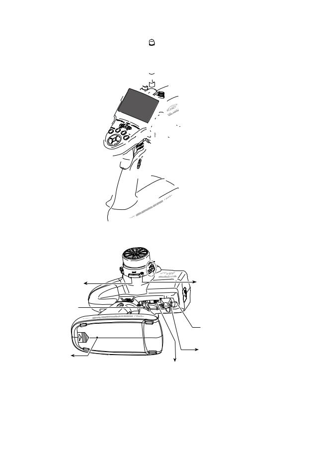
Transmitter T4PK
Nomenclature
|
Antenna |
Push switch 3 (PS3) |
|
|
Digital Dial 3 |
LCD screen |
(DL3) |
|
|
LED |
Digital Trim1 (DT1) |
(default steering trim) |
|
Power&Display |
Steering wheel |
switch |
|
Edit buttons |
Digital Trim 2 (DT2) |
|
|
Digital Dial 1(DL1) |
(default throttle trim) |
(default dual rate) |
Push switch 2 (PS2) |
|
|
Digital Dial 2(DL2) |
|
(default ATL) |
Grip Handle |
|
 Digital Trim 3 (DT3)
Push switch 1 (PS1) |
Wheel tension |
|
adjusting screw |
||
|


 Cover
Cover
Throttle trigger
 Trigger slide adjusting screw
Battery cover |
Mechanical ATL |
|
adjusting screw |
||
|
Trigger tension adjusting screw
*The switches, dial, and trimmers in the figure are shown in the initial setting position.
Precautions when turning the power switch on and off.
When the data was changed using the edit keys or trim levers, wait at least two seconds before turning off the power. If the power is turned off within two seconds after the data was changed, the new data will not be written to memory.
Before Using
15

Using Before
Power & Display Switch
The power switch and display switch of the T4PK are integrated. In the PWR ON mode, radio waves are transmitted and in the DISP ON mode, model data, settings can be checked without transmitting radio waves.
|
PWR ON |
|
Radio waves are being |
|
transmitted |
"RF" is displayed |
OFF |

 DISP ON
Radio waves are not being transmitted
"DISP" is displayed 

Power Off Forgotten Alarm
When the steering wheel, throttle trigger, push switch, or edit button is not operated for 10 minutes during T4PK initialization, an alarm sounds and "NOT OPERATED FOR A LONG TIME" is displayed on the LCD screen.
When the steering wheel, throttle trigger, push switch, or edit button is operated, the alarm is reset. If the system is not to be used, turn off the power.
The function can be deactivated at the system menu (p.108).
High Voltage Alarm
If a battery exceeding 8V is used with the T4PK, an audible alarm will sound and "HIGH VOLTAGE" will be displayed on the LCD screen.
Immediately remove the battery because it may cause damage to the T4PK.
Low Battery Alarm
If the transmitter battery voltage drops to 5.0V(when using dry cell battery: 4.2V) or less, an audible alarm will sound and "LOW BATTERY" will be displayed on the LCD screen.
Warning
When a low battery alarm is generated, cease operation immediately and retrieve the model.
If the battery goes dead while in operation, you will lose control of the model.
16

Digital Trim Operation
(Initial settings: DT1: Steering trim, DT2: Throttle trim, DT3: ------- |
) |
Digital trims can be used in 2 ways:
Operating by the lever: Push the lever to the left or right (up or down) Operating by push button switch: Press the push button switch in the desired direction. The current position is displayed on the LCD screen in the bottom three rows of the list. However, this operation cannot be performed when the trim/dial lock (p.22) function is set.
DT1
|
|
Steering trim display |
|
|
|
Throttle trim display |
|
|
|
ss%ACH STEPHIS INDICATED BYYA TONE |
|
|
|
ss7HEN THEHTRIM EXCEEDS THEHMAXIMUM TRIM ADJUST- |
|
|
|
ment range, the beep will change and the servo |
|
|
|
will not move any farther. Return to the neutral |
|
|
|
position (center) by pressing both the push button |
|
|
|
switches simultaneously for about one second. |
|
DT2 |
DT3 |
ss4RIM LEVER ADJUSTMENTSTHAVE NO EFFECTCON THEHMAXI- |
|
mum servo travel.This prevents the linkages from |
|||
|
|
||
Trim Operation |
|
BINDINGDWHEN ADJUSTMENTS ARE MADE |
With the center trim feature, trim adjustments have no effect on the maximum servo travel. This prevents the linkages from binding when adjustments are made.
Grip Dial Operation
(Initial setting: DL1; Steering D/R, DL2; ATL)
Operate the dials by turning them. The current set value is displayed on the LCD screen. However, this operation cannot be performed when the trim/dial lock (p.22) function is set.
 Steering D/R
display
 ATL display

 Steering D/R DL1
 ATL DL2
ss%ACH STEPHIS INDICATED BYYA TONE
ss7HEN THEHTRIM EXCEEDS THEHMAXIMUM TRIM ADJUSTMENT RANGE THEHTONE WILL CHANGE PITCHTANDNTHEHSERVO WILL NOTO
move any farther.
Before Using
17

Mechanical ATL Adjustment
Make this adjustment when you want to decrease the stroke of the brake (back) side of the throttle trigger for operation feel.
Using Before
Adjustment
1 5SING AA MM HEXXWRENCH NADJUST THEHTRIGGERG
brake (reverse) stroke. (The screw moves the throttle trigger stopper.)
s 7HEN THE SCREW IS TURNED CLOCKWISE THE STROKE BECOMES NARROWER !DJUSTJTHESSTROKEEWHILEHWATCHINGHTHENSCREW
Mechanical ATL adjusting screw
Note:
Once you have changed the mechanical stroke on the brake side, be sure to adjust the scale of the throttle channel accordingly by using the "Adjuster Function"
(page 114).
Due to this change, you also need to adjust in most cases the travel of the throttle servo by using "Data Setting."
Wheel & Trigger Tension Adjustment
Make this adjustment when you want to change the wheel or trigger spring’s tension.
Adjustment
1 5SING A MM HEX WRENCH ADJUST the wheel spring tension by turning
THEHSCREWWINSIDE THEHADJUSTINGSHOLE IN the arrow direction.
ss4HEHSPRINGNIS SETETO THEHWEAKESTSTENSIONSAT THEH factory.
ss7HEN THEHADJUSTINGSSCREWWIS TURNEDECLOCKWISE the spring tension increases.
Wheel tension |
Trigger tension |
adjusting screw |
adjusting screw |
Note:
The adjustment range is up to 7 to 8 turns from the fully tightened (strongest) position. If turned further than this, the adjusting screw may fall out.
18

Trigger Slide Adjustment
The throttle trigger position can be moved forward and backward.
Adjustment
15SING A MM HEX WRENCH LOOSEN THE trigger slide mounting screw by turning it slightly counterclockwise.
25SINGIAA MM HEXXWRENCH NTURNNTHEHTRIGGER SLIDE ADJUSTING SCREW AND ADJUST THE trigger slide position within the marked
RANGE 7HEN THEHADJUSTINGSSCREWWIS TURNEDE clockwise, the trigger slide moves away from the grip handle.
3Retighten the mounting screw loosened at step 1 and fasten the trigger slide
Adjust so that the bottom  mark does not exceed
the top marking line.
Trigger slide mounting screw
Ni-MH Battery Replacement |
Trigger slide adjusting screw |
The Ni-MH battery is connected by a Futaba J connector so that it can be removed when you will not be using the transmitter for a long time, or when replacing a dead battery with a spare battery.
ss!LWAYS USE ANS(4 & " BATTERY
Removal
1 Slide the transmitter battery cover in the arrow direction while pressing the part shown in the figure.
2Remove the Ni-MH battery and disconnect the connector.
3 Insert the connector of the new battery and load the battery into the transmitter.
4 Finish by installing the battery cover.
Battery cover
While pressing here Battery cover
Before Using
Caution
Pay full attention so that the battery cover deas not pinch the cable of the Ni-MH battery.
Pinching the cable by the battery cover can lead to an electrical shortage, fire and abnormal heat generation, which may cause burns and fire disaster.
Install the cover by aligning the claws at both sides of the battery cover with the grooves in the transmitter shown in the figure and sliding on the battery cover.
19

Using Before
Charging The HT5F1700B Battery
Charging
1 Plug the transmitter cord of the special char-
GEREINTO THEHCHARGING JACKKON THEHREAR OF THEH transmitter.
2 Plug the charger into an AC outlet.
3 Check that the charging LED lights.
When charging the HT5F1700B battery with the special charger, allow about 15 hours for charging. If the transmitter has not been used for some time, cycle the battery by charging and discharging it two or three times.
 AC outlet
Charger
Transmitter charging  LED
LED
To receiver |
|
|
|
To transmitter |
|||
Ni-Cd battery |
charging jack |
||


 Charging
jack


 Cover
Cover
When using Futaba CR-2000
The HT5F1700B is 5-cells, so, when charging the HT5F1700B battery with Futaba CR-2000 charger, you have to use the RX output side.
Over current protection
The transmitter charging circuit is equipped with an over current protection circuit (1.7A). If the battery is charged with a quick charger for other than digital proportional R/C sets, it may not be fully charged.
Warning
Never plug it into an outlet other than indicated voltage.
0LUGGING THE CHARGER INTO THEHWRONGGOUTLET MAYYRESULT INUAN EXPLOSION ISPARKING NOR lRE
Do not insert and remove the charger when your hands are wet.
It may cause an electric shock.
Always use the special charger or a quick charger for digital proportional R/C sets to charge a digital proportional R/C set Ni-MH battery.
/VERCHARGING AA.I -( BATTERYYCANARESULT IN BURNS lRE INJURIES OR LOSS OF SIGHTGDUEUTO OVERHEATING BREAKAGE OR ELECTROlyte leakage.
Caution
Never try to recharge a dry cell battery.
The transmitter may be damaged or the battery electrolyte may leak or the battery may break.
When the charger is not in use, disconnect it from the AC outlet.
Do this to prevent accidents and to avoid overheating.
20

Grip Vibrator
A vibrator is built into the grip of the T4PK. The vibrator vibrates at racing timer lap navigation, time-up, and low battery alarm. (p.116)
Display when power switch is turned on
Power switch turned on
Beep confirmation sound is generated and the initial screen shown below appears.
Battery voltage display
Edit button lock display
Total timer display (H:M)
Trim/dial lock display
-ODELDNAME CHARACTERS 
D i s p l a y m o d e c a n b e  changed by using the SYS-

4%-%FUNCTION 3EE3PGEE
Steering trim display 
Throttle trim display
 DL1
DL1
 DL2
DL2
DL3 Function names and rate as-
DT1 signed to dials are displayed.
 DT2
DT2


 DT3
DT3
*The current servo mode (servo |
"BLHT" is displayed when |
|
response) is displayed. |
backlighting is ON. |
|
The mode currently operating is |
|
|
displayed. ("HIGH"/"NOR") |
|
|
|
|
|
When radio waves are being emit- |
*The current receiver type is |
|
ted, "RF" is displayed. When radio |
displayed. |
|
waves are not being emitted when |
The type currently operating is |
|
turned on by display switch and |
displayed. |
|
when the DSC function is used, |
("C1"/"C2") |
|
"DISP" is displayed. |
||
|
||
|
|
Before Using
Power supply and voltage display
Dry cell batteries (alkali batteries are recommended) can be used with the optional battery box. However, when using dry cell batteries, set BATT-TYPE in the system menu to DRY 4CELL. When BATT-TYPE is set to DRY 4CELL, the voltage display of the initial screen will change to the symbol.
When using the T4PK standard HT5F1700B battery, always set BATT-TYP to NIMH 5CELL. (See page 108, for a detailed description of the battery types.)
User name display
When the (END) button is held down for 1 second or longer at the initial screen, the
Futaba logo and user name are displayed for about 2 seconds.
21
Using Before
Edit button lock and trim/dial lock
T4PK setup and operation by edit button (p.15) and digital trim DT1, DT2, and DT3 and dials DL1, DL2, and DL3 can be prohibited.
Setting
1Edit button lock: When the (+) button is pressed for about 1 second at the initial screen, a confirmation beep is generated and the edit button lock display 

 appears on the
screen.
Trim/dial lock: When the (-) button is pressed for about 1 second at the initial screen, a confirmation beep is generated and the trim/dial lock display 

 appears on the screen.
Clearing
1Edit button lock and trim/dial lock can be cleared in the initial screen state by the same
method as the setting described above. (The edit button lock display 

 or trim/dial lock display

 disappears from the screen.)
Total Timer
The total timer shows the accumulated time from last reset.
The total time does not change even when the model changes.
Reset method
1In the initial screen state, hold down the (+) and (-) buttons simultaneously for 1 second.
* The total timer display counts up from 1 minute to 99hours 59 minutes.
LCD Screen Contrast
The LCD screen contrast can be adjusted. (For more information, see page 108.)
Caution
Do not adjust the contrast so that the LCD is too bright or too dark.
When the display cannot be read due to a temperature change, data cannot be set.
LCD Screen Temperature Change
In the following cases, the LCD may become difficult to read due to a temperature change.
-On hot summer days and cold winter days, the LCD may be easy to read indoors, but difficult to read outdoors.
-If the contrast is too bright or too dark, temperature changes and lighting conditions may cause the screen to become difficult to read.
Contrast adjustment from main screen
1 Turn on the transmitter.
2 )F THE SCREEN IS TOO DARK ADJUST THE CONTRAST BY PRESSING THE BUTTON WHILE PRESSING THE */' BUTTON )F)THE SCREEN ISSTOORLIGHT ADJUST THE CONTRASTSBYYPRESSing the (+) button while pressing the (JOG) button.
22

Changing wheel position and modifying for left-hand use
Changing the wheel position
The wheel position can be offset by using the accessory APA wheel position offset adapter.
(See the page 24 for the modification method.)
Modifying for left-hand use
The wheel section left and right installation direction can be reversed.
(See the page 26 for the modification method.)
Angle can be adjusted
4HEHANGLEGCANABE lNELYEADJUSTED BY ADJUSTINGSTHEHSTEERINGNWHEEL UNIT INSTALLATION 3EE THEHMODIlCATIONIMETHOD ONITHENNEXT PAGEPFOR THE ADJUSTMENTDDETAILS
Removing the steering wheel unit
s /BTAIN A MM HEX WRENCH AND PHILIPS screwdriver.
1 Hold the wheel and remove the screw.
Steering wheel mounting screw
2 Pull off the wheel.
Wheel
3 Remove the 3 steering wheel unit mounting screws.
Unit mounting screws
Before Using
23

4 Remove the steering wheel unit.
s"E"CAREFULANOTETO STRETCH THE WIRING
5 Disconnect the steering wheel |
|
unit connector. |
Wheel unit |
Using Before
Installing the accessory APA steering wheel offset adapter
ss/BTAIN A MM HEXXWRENCH AND PHILIPS SCREWDRIVER ss)NSTALLSTHEASTEERINGNWHEELWUNIT EREMOVED AS DESCRIBED ONDTHEOPRECEDINGEPAGE AS FOLLOWS
ss4HEHLENGTH OFNTHETSCREWS USEDUAT EACH PARTTDIFFERSR 7HEN REASSEMBLING THE STEERINGNWHEELWUNIT EALWAYS USE THE original screws.
1 The steering wheel unit connector through the adapter.
Adapter APA
2 Install the steering wheel unit us-
ing the 3 mounting screws. |
Unit mounting screws |
|
3 Connect the steering wheel unit connector.
(be careful of the direction of the connector)
24

3 Pull out the wiring as far as possible from between the wheel unit and APA. Stow the surplus pulled out wiring in the transmitter.
s"E"CAREFULANOTETO STRETCH THE WIRING
Stow the surplus wiring here. |
|
4 Install the assembled wheel unit and APA |
|
to the transmitter using the screw supplied. |
|
The APA mounting screws are in the hook |
|
and APA mounting screws bag. |
|
Verify the position of the transmitter bottom |
|
holes by mounting angle. The screw used |
Transmitter bottom hole |
depends on the position of the bottom hole. |
|
*The figure below is an installation example.
Before Using
$UMMYYSCREWS XX SCREW hide the APA hole where there is no bottom hole in the transmitter.
Dummy screw
5SEE X CAPPTAPPINGGSCREW TOOINSTALLLTHEE!0!!AT the 3 bottom holes in the transmitter
5 Install the steering wheel using the screw.
Steering wheel mounting screw
25

Using Before
Modifying for left-hand use
ss/BTAIN A MM HEXXWRENCH AND PHILIPS SCREWDRIVER
ss)NSTALLSTHEASTEERINGNWHEELWUNIT REMOVED AS DESCRIBED ONDTHEOPRECEDING PAGENAS FOLLOWS
1 Remove the wheel section rear
cover .
ss4HEHREAR COVER CANABE EASILY REMOVED BY INserting a coin, etc. into the slot at the bottom of the rear cover.
2 Push in the disconnected connector so that it can be connected at the opposite side.
3 At the opposite side, connect the steering wheel unit connector and Install the steering wheel unit, steering wheel cover, and wheel to their original positions.
s !T THIS TIME BE SURE THAT THE WIRING IS NOT pinched between the wheel unit and transmitter.
Stow the surplus wiring here.
26

Installing the accessory Hook
A hook can be installed to the T4PK, as required.
The hook is in the hook and APA mounting screws bag supplied with the set.
ss/BTAIN A APHILIPSASCREWDRIVER ss0ULL UPLTHE GRIP RUBBER
1 Pull up the bottom of the grip rubber as shown in the figure.
Grip rubber 


 Using
Using 


 Before 2 Pull out the grip rubber in the arrow


direction.
3 There is a mounting nut inside the |
|
|
transmitter. Install the hook at the |
Hook |
|
position shown in the figure using |
||
|
||
the accessory screw w/washer. |
|
|
Hook mounting screw |
4 Return the grip rubber to its original |
|
position. |
Hook |
27

Using Before
About Transmitter Antenna and Receiver
About The Transmission Antenna
!DJUST THE ANTENNA VERTICALLY |
Antenna |
to the ground. |
|
A B
Antenna Moving Range
Warning
!DJUSTJTHESANTENNAHVERTICALLYATO THE GROUND
Otherwise, the operating range may become shorter.
Never hold only the antenna.
Hold the grip handle, otherwise the antenna may be damaged.
The antenna position can be changed in the range as shown in figures A and B. However, please do not apply unnecessary force or shock.
The internal cable may be damaged; thus transmitting distance decreases and it may cause malfunction.
4HEHANTENNANIS A SCREW ON TYPE ANDYCANEBE REMOVED (OWEVER DO NOTOREMOVEETHETANTENNAAEXcept when it must be replaced.
If the transmitter antenna terminals get dirty, the radio wave output will become weak and there is the danger that the receiving range will be substantially shortened.
When the antenna is changed, it requires the metal part of the antenna to be held firmly while putting it on.
The antenna can not be mounted to T4PK (by rotating the middle part of the antenna).
There might be small glitch when the antenna of transmitter is brought close to servos, ESCs or other peripheral devices.
This is not an issue but please keep this symptom in mind especially when setting-up.
Antenna
When the antenna is changed, it requires the metal par t of the an - tenna to be held firmly while putting it on.
28

Receiver Terminology
|
|
Tactile switch/LED |
|
Antenna |
#OAXIALLCABLE |
Connectors |
|
|
|
B/4 |
:CH4 servo(CH4)/Power connector |
|
|
3 |
:CH3 servo(CH3) |
|
|
2 |
:Throttle servo(CH2) |
|
|
1 |
:Steering servo(CH1) |
|
|
DSC |
:DSC connector |
How to link the transmitter and the receiver
Each transmitter has an individually assigned, unique ID code. In order to start operation, the receiver must be linked with the ID code of the transmitter to which it is being paired. Once the link is made, the ID code is stored in the receiver and no further linking is necessary unless the receiver needs to be used with another transmitter.
Link procedure
1 Bring the transmitter and the receiver close to each
OTHER WITHIN HINCHES HALF METER
2 Turn on the transmitter.
3 Turn on the receiver.
4 Push the tactile switch of the receiver.
When the link is complete, the LED in the receiver changes to solid green.
Precaution:
)F THEREEARERMANYY&!334 SYSTEMSTTURNEDEON IN CLOSEOPROXIMITY TO THEH2 &3 2 && 2 &3 YOURU receiver might not link to your transmitter. In this case, even if the receiver's LED stays solid green, unfortunately the receiver might have established a link to one of other transmitters. This is very dangerous if you do not notice this situation. In order to avoid the problem, we strongly recommend you to doublecheck whether your receiver is really under control by your transmitter by giving the stick input and then checking the servo response.
Before Using
Warning
After the linking is done, please cycle receiver power and check if the receiver to be linked is really under the control of your transmitter.
Do not perform the linking procedure with motor's main wire connected or the engine operating as
IT MAYYRESULT INUSERIOUS INJURY
*Please refer the table below for LED status vs receiver's condition.
LED status vs receiver's condition:
No signal reception |
Red : On |
Receiving signals |
Green: On |
Receiving signals, but ID is unmatched. |
Green: Blink |
Unrecoverable failure (EEPROM, etc.) |
Red and Green turn on alternately |
|
|
29

Using Before
Receiver Installation
Install the R604FS receiver on the car as follows:
The operating range may become shorter, depending on where the receiver and the antenna are mounted.
WARNING
Do not cut or bundle the receiver antenna wire. |
|
Antenna |
|
||
|
tube |
$O NOT BENDTTHEBCOAXIAL CABLE )T)CAUSES DAMAGE
Antenna
Install the antenna in the higher place as shown in the figure.
Put the antenna in the antenna tube to protect it.
Coaxial cable
Keep the antenna as far away from the motor, ESC and other noise sources as you possibly can.
Wrap the receiver with something soft, such as foam rubber, to |
|
avoid vibration. If there is a chance of getting wet, put the receiver |
R604FS |
in a waterproof bag or balloon. |
Note:Since the receiver generates a certain amount of heat, change the mounting method to improve the ventilation at the receiver. If the receiver is too tight, it may malfunction when the ambient temperature is high.
Caution
Always use R604FS under the following conditions:
"ATTERYY 6 .I #D.BATTERY
28 4YPE &!334 # 3EE P FOR SETTING METHOD G
4RANSMITTERIMODE ()'( 30%%$DMODE 6 &UTABA DIGITAL SERVO 3EEEP FOR SETTING METHOD
4RANSMITTERIMODE ./2-!,MMODE 6 &UTABA ALL SERVO 3EE3P FOR SETTING METHOD
Under other conditions, the set will not operate, or the specified performance will not be displayed even if it operates. In addition, it may cause trouble of servo and other equipments. Futaba will not be responsible for damage, etc. caused by combination with the products of other companies.
In addition, the FSU1 Fail Safe Unit cannot be used because the system is different. Use the fail safe function of the transmitter.
Transmitter mode setting
3ETETHE TRANSMITTERITO THE ()'(T30%%$TMODE OR(./2-!, MODE 3EE PAGEA FOR A DESCRIPTION OFO the setting method.
Note: However, use of a digital servo (including BLS Series brushless servo) can only be used in the HIGH SPEED mode.
When the power is turned on, whether the receiver is in the HIGH SPEED or NORMAL mode is judged and the R604FS operates in that mode until the power is turned off. When the transmitter mode was changed, operation becomes possible when the receiver power is turned on again. When the frequency band was changed, reception on the new frequency band becomes possible when the receiver power is turned on again.
For the receiver, servos, and other connections, see page 31 For the DSC cord (option) connections, see page 123.
30

Installation
Receiver and Servo Connections
Connect the receiver and servos as shown below. Connect and install the receiver and servos in accordance with "Installation Safety Precautions" on the next page.
The figure shown below is an example. The method of connecting the motor controller to the motor and battery depends on the motor controller used. Purchase the motor controller and servos separately. The receiver also depends on the set.
When using a 4-channel servo, connect the optional double extension cord to 4/B of the receiver and connect the 4-channel servo and receiver switch to the connection at the opposite side.
Installation When A Erectronic Speed Control Is Used
+ |
Installation |
|
|
- |
|
Installation For Gas Powered Models
Switch
4/B |
Steering servo |
To Battery
Throttle servo
Receiver
CH3 servo
31
 Loading...