


Futaba
DIGITAL PROPORTIONAL RADIO CONTROL
PCM1024ZA
PCM1024ZH
PULSE CODE MODULATION SYSTEM

Thank you for purchasing
a Futaba digital proportional radio control set. Please read this manual carefully
before using your set.
ATTENTION:
1. Application of Product
This product is not intended for use in any application other than for the control of models for hobby and recreational purposes. This product is subject to regulations of the Ministry of Radio/Telecommunications and is restricted under Japanese low to such purposes. The laws of other countries may similarly restrict the use of this product. Futaba is not responsible for any use that is not in compliance with applicable law.
2. Exportation of Product
If the product is exported from Japan, the prior approval of the Ministry of Radio/Telecommunications is required regarding the country of destination. If this product is reexported from other countries, it may be subject to restrictions on such reexport and prior approval of government authorities may be required.
3. Modification, Adjustment & Replacement of Parts
Futaba is not responsible for any use of this product that is not in compliance with applicable law and disclaims all responsibility for any modification or alteration of the product, including the incorporation of the product into other products by third parties, that is not in compliance with appli-
cable |
law. |
|
ATTENTION: |
|
The product that you have purchased contains a rechargeable battery. |
|
The battery is recyclable. At the end of its useful life, under various state |
|
and local laws, it may be illegal to dispose of this battery into the |
Ni-Cd |
municipal waste stream. Check with your local solid waste officials for |
details in your area for recycling options or proper disposal. (For U.S.A.) |
THE FOLLOWING STATEMENT APPLIES TO THE RECEIVER
This device complies with part 15 of the FCC Rules.
Operation is subject to the following two conditions:
(1)This device may not cause harmful interference, and
(2)This device must accept any interference received,
including interference that may cause undesired operation. (For U.S.A.)
TABLE OF CONTENTS
System Features . . . . . . . . . . . . . . . . . . . . . . |
2 |
|
Introduction . . . . . . . . . . . . . . . . . . . . . . . . |
3 |
|
System Usage . . . . . . . . . . . . . . . . . . . . . . . . |
4 |
|
Manual Layout . . . . . . . . . . . . . . . . . . . . . . . |
6 |
|
FLYING SAFETY . . . . . . . . . . . . . . . . . . . . . |
7 |
|
Notable System Features . . . . . . . . . . . . . . . . . |
9 |
|
PCM 1024Z System Contents. . . . . . . . . . . . . . . |
10 |
|
Power-On Screen Displays . . . . . . . . . . . . . . . . . |
11 |
|
Working With The CAMPac Memory Module . . . . . |
.12 |
|
Using The Soft Keys . . . . . . . . . . . . . . . . . . . . |
13 |
|
Operation Without Radio Transmission . . . . . . . . . |
14 |
|
System Monitor Lights & Warnings . . . . . . . . . . . . |
14 |
|
System Status and Alarm Displays . . . . . . . . . . . . |
15 |
|
Using Your Futaba System Contents. . . . . . . . . . . |
16 |
|
Radio Installation . . . . . . . . . . . . . . . . . . . . . |
17 |
|
Charging & Direct Servo Connect Operation . . . . . |
.18 |
|
Stick |
Length Adjustment . . . . . . . . . . . . . . . . . |
19 |
Stick |
Tension Adjustment . . . . . . . . . . . . . . . . . |
19 |
Stick |
Angle Adjustment . . . . . . . . . . . . . . . . . . |
20 |
Antenna Angle Adjustment . . . . . . . . . . . . . . . . |
20 |
|
Transmitter Battery Replacement . . . . . . . . . . . . |
21 |
|
Rubber Protective Pad Installation . . . . . . . . . . . . |
21 |
|
Transmitter RF Module . . . . . . . . . . . . . . . . . . |
35 |
|
Synthesized Frequency Module & Receiver . . . . . . |
.99 |
|
Flight Condition Switching . . . . . . . . . . . . . . . . |
23 |
|
SYSTEM MENU |
|
|
Contents . . . . . . . . . . . . . . . . . . . . . . . . . . . |
94 |
|
MSL - Model Selection . . . . . . . . . . . . . . . . . . . |
95 |
|
VLT - Battery Voltage Display. . . . . . . . . . . . . . . |
26 |
|
TAC - Tachometer . . . . . . . . . . . . . . . . . . . . . |
97 |
|
SRV - Servo Cycle & Bar Graph Display . . . . . . . . . |
93 |
|
TRN - Trainer System . . . . . . . . . . . . . . . . . . . |
99 |
|
DTN - Data Transfer Function . . . . . . . . . . . . . . |
30 |
|
CPM - Copy Model Function . . . . . . . . . . . . . . . |
31 |
|
CPC - Copy Condition Function . . . . . . . . . . . . . |
39 |
|
PAR - Parameters (Sets Auto-Off and |
|
|
|
Screen Contrast) . . . . . . . . . . . . . . . . . . |
33 |
UNAUser Name Registration . . . . . . . . . . . . . . |
34 |
|
FRO - Trans. Freq. Set . . . . . . . . . . . . . . . . . . |
35 |
|
Setting The Frequency Synthesizer Receiver . . . . . . |
36 |
|
SWT - Switch setting . . . . . . . . . . . . . . . . . . . . |
37 |
|
MODEL SETTING SECTION |
|
|
C o n t e n t s . . . . . . . . . . . . . . . . . . . . . . . . . . . |
39 |
|
CSL - Condition Select . . . . . . . . . . . . . . . . . . |
40 |
|
TIM - Timers & Elapsed Time Counter . . . . . . . . . |
41 |
|
F/S - |
Failsafe/Hold Setting . . . . . . . . . . . . . . . . |
42 |
PMD - Pulse Mode FM/PCM . . . . . . . . . . . . . . . . |
43 |
|
REV -Servo Reversing Function . . . . . . . . . . . . . |
44 |
|
FNC - Function Control . . . . . . . . . . . . . . . . . . |
45 |
|
RST |
- Data Reset . . . . . . . . . . . . . . . . . . . . . . |
46 |
CUT - Engine Cut . . . . . . . . . . . . . . . . . . . . . |
47 |
|
CHD - Condition Hold . . . . . . . . . . . . . . . . . . . |
48 |
|
TYP - Model Type Selection . . . . . . . . . . . . . . . |
49 |
|
CH9Channel 9 Switch Definition . . . . . . . . . . . |
50 |
|
MNA - Model Name Definition . . . . . . . . . . . . . . |
51 |
|
ALT - Alternate Switch . . . . . . . . . . . . . . . . . . |
52 |
|
THR |
- Throttle Curve . . . . . . . . . . . . . . . . . . . |
53 |
SWH |
-Swashplate Type . . . . . . . . . . . . . . . . . . |
54 |
RDR - Rotor Direction . . . . . . . . . . . . . . . . . . |
56 |
|
INV - |
Inverted Pitch . . . . . . . . . . . . . . . . . . . . |
57 |
PIT - Pitch Curve . . . . . . . . . . . . . . . . . . . . . . |
58 |
|
COMMON CONDITIONS |
|
|
C o n t e n t s . . . . . . . . . . . . . . . . . . . . . . . . . . . |
59 |
|
ATV - Adjustable travel volume & Channel delay . . . |
60 |
|
AFR - Adjustable function rate . . . . . . . . . . . . . . |
62 |
|
D/R - Dual rates & EXP curve. . . . . . . . . . . . . . . |
64 |
|
Manual Introductory Section
PMX - Programmable mixing . . . . . . . . . . . . . . . 65 STM - Subtrim . . . . . . . . . . . . . . . . . . . . . . . 68 TOF - Trim offset . . . . . . . . . . . . . . . . . . . . . 69 CNA - Condition naming . . . . . . . . . . . . . . . . . 70 TRM • Digital trim . . . . . . . . . . . . . . . . . . . . . 71
AIRPLANE SECTION |
|
|||
Table of Contents . . . . . . . . . . . . . . . . . . |
. . . 73 |
|||
Airplane Controls & Functions . . . . . . . . . . . |
. . . 74 |
|||
Airplane Receiver and Servo Connections . . . . . . |
. . 76 |
|||
Airplane Setup Instructions . . . . . . . . . . . . . . |
. . 77 |
|||
Aileron Differential [ADF] . . . . . . . . . . . . . . |
. . 80 |
|||
Rudder Coupling [A—R] . . . . . . . . . . . . . . . |
. . 81 |
|||
V-Tail [VTL] . |
. |
. . . . . . . . . . . . . . . . . . . . |
. . 32 |
|
Rudder—Aileron |
[R-A] . . . . . . . . . . . . . . . |
. . 83 |
||
Elevons [EVN] |
|
. . . . . . . . . . . . . . . . . . . . . |
. . 84 |
|
Elevator-»Flap [E—F] . . . . . . . . . . . . . . . . . |
. . 85 |
|||
Flap-Elevator mix [F—E] . . . . . . . . . . . . . . . |
. . 86 |
|||
Collective Pitch [CPT] . . . . . . . . . . . . . . . . |
. . 37 |
|||
Ailvators [ALV] |
. . . . . . . . . . . . . . . . . . . . |
. . 33 |
||
Flaperons [FPN] |
. . . . . . . . . . . . . . . . . . . . |
. . 39 |
||
Airbrake [ABK] |
. . . . . . . . . . . . . . . . . . . . |
. . 91 |
||
Snap Roll [SNP] |
. . . . . . . . . . . . . . . . . . . . |
. . 93 |
||
Throttle Curve Adj. (TCV) . . . . . . . . . . . . . . |
. . 94 |
|||
HELICOPTER SECTION |
|
|||
Table of Contents . . . . . . . . . . . . . . . . . . . |
. . 95 |
|||
Helicopter Controls . . . . . . . . . . . . . . . . . . |
. . 96 |
|||
Helicopter Receiver and Servo Connections . . . . . |
. . 93 |
|||
Sample Helicopter Setup Instructions . . . . . . . . |
. . 99 |
|||
Pitch Curve [PCV] . . . . . . . . . . . . . . . . . . . |
. .104 |
|||
Hovering Pitch |
[PHV] . . . . . . . . . . . . . . . . . |
. . 105 |
||
Pitch Trim [PTM] . . . . . . . . . . . . . . . . . . . |
. . 106 |
|||
Throttle Curve [TCV] . . . . . . . . . . . . . . . . . |
. .107 |
|||
Hovering |
Throttle [THV] . . . . . . . . . . . . . . . |
. . 108 |
||
Hovering |
Offset |
[HOF] . . . . . . . . . . . . . . . . |
. . 109 |
|
Throttle Hold [HLD] . . . . . . . . . . . . . . . . . |
. .110 |
|||
Swashplate Type [SWP] ................................... |
111 |
|||
Pitch—Rudder |
[P—R] . . . . . . . . . . . . . . . . . |
. .112 |
||
Rudder—Throttle |
[R—T] . . . . . . . . . . . . . . . |
. . .113 |
||
Gyro Sensitivity |
[ G Y R ] . . . . . . . . . . . . . . . . |
. . 114 |
||
Acceleration [ACC] ........................................ |
115 |
|||
Inverted |
Pitch |
|
[INV] . . . . . . . . . . . . . . . . . |
. .117 |
SAILPLANE SECTION |
|
|||
Table of Contents . . . . . . . . . . . . . . . . . . . |
. . 118 |
|||
Sailplane |
Condition Menus . . . . . . . . . . . . . . |
. . 119 |
||
Sailplane Transmitter Controls and Functions . . |
. . .120 |
|||
Sailplane Receiver and Servo Connections . . . . . |
. .121 |
|||
Example Sailplane Setup Instructions . . . . . . . . |
. . 195 |
|||
Aileron Differential [ADF] . . . . . . . . . . . . . . |
. . 125 |
|||
Aileron—Rudder Mixing [A-R]. . . . . . . . . . . . |
. .126 |
|||
Aileron-Speed Flap Coupling [ASF] . . . . ......................... |
.127 |
|||
V-Tail [VTL] |
|
. . . . . . . . . . . . . . . . . . . . . . |
. .128 |
|
Airbrake Mixing [ABE] . . . . . . . . . . . . . . . . |
. . 129 |
|||
Elevator—Brake |
Flap Mixing [EBF] . . . . . . . . . .... |
. 1 3 0 |
||
Elevator—Speed Flap Coupling (ESF) . . . . . . . . |
. .131 |
|||
Brake Flap Mixing [BKF] . . . . . . . . . . . . . . . . . . . . . |
. . .132 |
|||
Speed Flap Mixing . . . . . . . . . . . . . . . . . . . |
. . 135 |
|||
Speed Flap Trim [SFT] . . . . . . . . . . . . . . . . |
. . 139 |
|||
Butterfly Mixing [BFY] . . . . . . . . . . . . . . . . |
. . 140 |
|||
Butterfly Trim Mix [BYE] . . . . . . . . . . . . . . |
. . 142 |
|||
Elevator Trim (ETM) . . . . . . . . . . . . . . . . . |
. . 143 |
|||
Trim Mix 1 [TM1] & Trim Mix 2 [TM2] - 4-S . . . |
. . 145 |
|||
Flap-Elevator mix [F—E] . . . . . . . . . . . . . . . |
. ..147 |
|||
Elevator-Flap Mix [E—F] . . . . . . . . . . . . . . . |
. . . 143 |
|||
Flaperon Mixing (FPN] - 2-S . . . . . . . . . . . . . |
. . 149 |
|||
COMMAND LIST . . . . . . . . . . . . . . . . . . . |
. . 151 |
|||
Manual Introductory Section, Page 1
Manual Introductory Section
Futaba's PCM 1024Z series of radio control systems is the most sophisticated available for aircraft, helicopters, and sailplanes. Inside this radio is the logic necessary to control virtually any aircraft imaginable (both transmitter types are programmed for all three aircraft).
Built into the system are a number of menus designed to make it simple to tailor the system's programs for YOUR aircraft. Multiple menus provide unparalleled control of every aspect of the model's setup, even some that you probably never thought of before!
System Features:
• 1024 High resolution system
•9 Channels (select channel order)
•10-Model Memory
•8-Character Model names
•16 added memories with CAMPac Module
•Up to 8 flight conditions for each model
•5 programmable mixers with special advanced
|
functions for each model setup |
• |
Each flight condition separately programmable |
• |
Flight condition & channel delay setting |
•Ready for aircraft, helicopters, and sailplanes
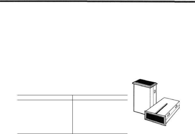
•Deluxe carrying case included
•Carrying handle
• Ergonomic shape easy to hold and operate
•Attractive neckstrap and mount
•Ball bearing control sticks
•Adjustable tension control sticks
• Adjustable length control sticks
•Adjustable angle control sticks
•Programmable transmitter switches
• |
Large liquid-crystal display |
|
• |
Contrast |
adjustment |
• |
Soft keys |
make programming simple |
•Switchable FM/PCM
•Optional synthesized frequency module & receiver
•Unique Digital Trim function (2 rates)
•Electronic servo centering, reversing, throw volume, exponential
•Failsafe/Hold setting
• Powerful data copy functions
•Swiveling antenna stores in transmitter
•Detachable battery pack
•Two separate timers & elapsed time counter
• Automatic system power-off
•Low-voltage alarm
•Special Mixer alarm
•Voltmeter with adjustable load for transmitter and receiver batteries
•Built-in tachometer
•DSC System
•Trainer system
Airplanes
•Aileron Differential [ADF]
•Rudder Coupling [AS-R]
• |
V-tail [VTL] |
|
• |
Rudders-Aileron |
[R-A] |
• Elevons [EVN] |
|
|
• |
Elevators-Flap [E-F] |
|
• |
Flaps-Elevator |
[F-E] |
•Collective pitch [CPT]
•Differential elevators [ELV]
•Flaperons [FLP]
• |
Airbrake |
[ABK] |
• |
Snap Roll |
[SNP] |
• Throttle Curve Adj. [TCV] (12 segment)
Helicopters
Pitch Mixing [PCV]
Hovering Pitch [PHV]
Pitch Trim [PTM]
Throttle Curve [TCV]
Hovering Throttle [THV]
Hovering Offset [HOF]
Throttle Hold [HLD]
Swashplate type [SWH]
Pitch-Rudder [P-R]
Rudder-Throttle [R-T]
Gyro Sensitivity [GYR]
Acceleration [ACC]
Inverted Pitch [INV]
Throttle curve adj. [THR]
Rotor Direction [RDR]
Sailplanes (Select from 2, 4, or 5-servos in wing)
• |
V-tail |
[VTL] |
|
• |
Differential adjustment |
[ADF] |
|
• |
Rudder |
coupling [A-R] |
|
• |
Aileron-flap coupling [ASF] |
||
• |
Airbrake/Spoiler/Gear |
trim compensation [ABE] |
|
•Elevator-flap coupling [EBF, ESF]
•Flap trim setting [SFT]
•Butterfly (Spoileron or Crow) [BFY]
•Butterfly trim mix [BYE]
•Elevator trim sets [ETM]
• |
Flap-Elevator |
mix |
[F-E] |
• |
Elevator-Flap |
mix |
[E-F] |
• |
Flaperon mixing [FLP] |
||
Manual Introductory Section, Page 2

Manual Introductory Section
INTRODUCTION
Thank you for selecting the Futaba® PCM1024Z Radio System. The design of this system has absolutely no compromises.
You |
now possess a system that w i l l allow |
you |
to fly your model — airplane, helicop- |
ter, or sailplane — with the highest performance possible. With a / / the power in this system, setting up and adjusting is very simple. We recommend that you read the manual carefully to learn about the programming features, but if you are in a hurry, follow the example set-up instructions in the beginning of the model setup procedures sections. We have provided detailed examples for power aircraft, helicopters, and sailplanes (with two, four, and five wing servos).
The transmitter can be used with any model type by using the desired special mixing menus for the model you are interested in — a / / menus are contained in both types of transmitters. The transmitters for airplanes and sailplanes (PCM 1024ZA) contain snap r o l l direction switches and a different throttle stick feel than the helicopter system (PCM 1024ZH).
The PCM 1024ZA System Transmitter uses a unique menu system, which allows the utmost in versatility. In stead of a single, complicated loop that forces the user to "step through" each menu on the way to the desired setting, the PCM 1024ZA allows you to proceed directly to the menu that you need, bypassing those that do not need any inputs. This system makes setting up models both rapid and simple.
You may define different groups of settings that may be called up by the setting of a single FLIGHT CONDITION switch. You may program up to eight different flight conditions for each model in the main memory area.
The exclusive optional synthesized transmitter module and receiver allow you to choose any frequency available without switching crystals or modules, or changing receivers. Electronically-activated trims are memorized for each model in memory, and can't be accidentally moved while the transmitter is off. The optional CAMPac Memory Module can store additional model setups and easily transfer them to other PCM1024Z transmitters.
All in a l l , the Futaba PCM1024Z is the most advanced radio control system in the world — we know that you enjoy using it for pleasurable flying!
Manual Introductory Section, Page 3

Manual Introductory Section
SYSTEM USAGE
The PCM 1024Z system that you have just purchased has been designed to be the most versatile radio system possible. Because of this, a few words about the layout of the radio are called for. You are already aware that the PCM 1024Z transmitter has numerous model memories, but it is important to understand that each model memory may have several flight condition setups that may be switched during flight! This means that you may really call up different trim settings, mixing, and control feel as you fly the model. For example, an aircraft could have different takeoff and acrobatic settings; a helicopter could have different settings for hovering, aerobatics, and autorotation; a sailplane might be set up with independent settings for launching, thermal I ing, speed, and landing. Switching between these different settings is as easy as flipping a switch.
To accommodate this power, the PCM 1024Z system has four levels of operation: the Home Menu, the System Menu, the Model Menu, and the Condition Menu. The Home Menu appears when the system is first turned on, and displays such items as battery voltage, trim positions, one or more timers, and other functions. The top level display is what is normally displayed during operation.
The next level down is the System Menu. The System Menu is used to choose and call up the items that apply to all model setups stored within the PCM 1024Z transmitter. This menu includes such items as Model Select (which chooses which model setup to use), Copy Model and Copy Condition, User Name inputting. Switch Setting, and other items.
Next comes the Model Menu, which contains unique information about each model stored within the PCM 1024Z's memory.Within this menu are settings that pertain to a particular model. Of course, these settings can vary for each different model. As an example, the Model Menu contains the Servo Reversing function, which may be different for each model stored.
Finally, you will find the Condition Menus. These menus are customized to the different types of models the PCM 1024Z system will accommodate: Airplane, Helicopter, and Sailplane (the three sailplane menus are further broken into the categories of 5 wing servos, 4 wing servos, and 2 wing servos). In the Condition Menus, you may set up throws, mixing functions, and other items that vary with flight conditions but are associated with one model setup.
As mentioned earlier, the PCM 1024ZA System Transmitter uses a unique menu system, which allows the utmost in versatility. The PCM 1024ZA allows you to proceed directly to the menu that you need, bypassing those that do not need any inputs, instead of forcing the owner to proceed through a single, complicated loop one menu at a time on the way to the desired setting. This system makes setting up models both rapid and simple.
This menu configuration is illustrated below.
Manual Introductory Section, Page 4

Manual Introductory Section
Startup Menu
Shows during regular operation
System Menu
Settings that apply to all models in storage
Model Menu 1 |
Model Menu 2 |
Model Menu 10 |
|
Settings |
for |
Settings for |
Settings for |
Model |
#1 |
Model #2 |
Model #10 |
Condition Menus |
Condition Menus |
Condition Menus |
|
Settings for all |
Settings for all |
Setting for all |
|
conditions for |
conditions for |
conditions for |
|
Model |
#1 |
Model #2 |
Model #10 |
Condition #1 |
Condition #1 |
Condition #1 |
|
Model |
#1 |
Model #2 |
Model #10 |
Condition #2 |
Condition #2 |
Condition #2 |
|
Model |
#1 |
Model #2 |
Model #10 |
conditions3-7 |
|
|
|
Condition #8 |
Condition #8 |
Condition #8 |
|
Model |
#1 |
Model #2 |
Model #10 |
Manual Introductory Section, Page 5

Manual Introductory Section
MANUAL LAYOUT
The instructions contained in this book are written in great detail so that you may easily understand the capabilities of your PCM 1024Z system. We recommend that you spend some time reading these instructions so that you can have a good feel of what the system can do.
After this introduction are some words about safety and proper operation of your Futaba system. Next is a section on general operational principles, including adjustments that you can make on the transmitter to make it 'fit'your flying style.
Next are instructions for system-level programming. This system-level programming is important because it is used with all three types of models that the PCM 1024Z system can be set up for. This includes model menu selection, system voltmeter operation, tachometer usage, servo bar graph display, trainer setup, and model data transmission and copying.
A section on general model settings follows. This section covers the topics of model setup that are common to all model types, such as setting throws, servo reversing, type selection, model naming, and others. The remainder of the menus are specific to the particular type of model.
After the general section is a list of the common condition menus that apply to all three types of aircraft that the 1024A system can accommodate. This is followed by three sections which describe the setup procedures for aircraft, helicopters, and sailplanes. At the beginning of each model setup section is an example setup procedure that describes all the steps needed to set up all the desired flight conditions for a model. Each of these sections assume that you are familiar with the general system-level operations sections.
The rear of the manual contains blank data tables that may be used to record the data that you have programmed into your system, and contains technical details of this system. Be sure to make a photocopy of the blank data tables before you write in them.
We hope that you find the PCM 1024Z System Manual very hopeful. Please feel free to write to Futaba if you feel that any corrections or clarifications should be made.
Manual Introductory Section, Page 6

Manual Introductory Section
FLYING SAFETY
Safety is very important when you are flying radio-controlled models. If you fail to follow the installation, setup, and operation instructions in this manual, or if you ignore warnings or rules set by others, you may cause the partial or total destruction of your radio control system, aircraft, and endanger yourself or other persons or property. You are responsible for safe operation of your model, and may be held liable for any damages your activities cause.
Please maintain your system properly. Install it in your aircraft using the proper procedures, inspect the model frequently for correct operation and structural and control authority, and be certain that you are capable of handling the model in unusual situations. Do not fly over or near spectators or where your model could injure any person or property. Do not fly unless you are sure of your flying skills, radio installation, and model integrity. Please ask for assistance from an experienced pilot if you are not sure about your qualifications.
Before flying, carry out a range check on the ground with the transmitter antenna extended only one step. Note the distance you can achieve without loss of control — it should be at least 30 paces. We recommend a range check before each flying session to verify that your system is working properly.
When flying, be sure the antenna is fully extended. If the antenna is not fully extended, your model'seffective range is reduced, and interference can cause difficulties even at short range.
Be sure that you do not shorten the receiver antenna, either by cutting some off, or by coiling the excess up. Instead, let the excess length trail behind or below the aircraft. Cutting the antenna will reduce the effective range of the system and increase the chance of interference.
When turning on your radio system, first turn on the transmitter, then turn on the receiver. When turning off the power, turn off the receiver first, then the transmitter. If these turn-on sequences are performed in reverse order, the receiver may pick up spurious signals and cause the servos to drive hard over, causing possible damage to the radio system and the control linkages.
Manual Introductory Section, Page 7

Manual Introductory Section
If you are using the Synthesized transmitter module FP-TK-FSS, be sure that you know the transmitting frequency before switching on. If you don't know thefrequency, hold the [A] or [R] key down as you switch on power. The transmitting frequency will be displayed but radio transmission is deactivated. Once you have determined the frequency, secure the appropriate frequency control device and turn on power to operate normally.
Be sure to charge the transmitter and receiver batteries fully. If the
system has not been used for a long time, be sure to charge at least Recharge 24 hours before using the system, and check both batteries with the
system voltmeter at high load (500 mA). The transmitter battery should remain above 9.4 volts, and the receiver should be above 4.7 volts. IF EITHER BATTERY INDICATES LOWER THAN THIS, DO NOT FLY. Recharge the batteries first.
Do not quick charge the battery. Overcharging the battery will cause the battery to overheat and creates a very dangerous situation.
Do not expose your system to rain or allow water to get inside the case. If water does penetrate the case, control of the model could be lost, resulting in a crash and danger to others. Use a waterproof cover or wait until the conditions are dry before attempting to fly.
Manual Introductory Section, Page 8
Manual Introductory Section
PCM 1024Z NOTABLE SYSTEM FEATURES
•The optional CAMPac memory module stores up to 10 model setups, and may be exchanged between different PCM 1024Z transmitters so that model data may be rapidly transferred, or backed up.
•The telescoping antenna is stored within the transmitter, but when it is extended, it may be easily rotated in any direction using the spherical joint on the top of the transmitter case.
•Flight Condition Switching allows preset mixing,
trims, and other data to be matched to existing flight conditions immediately upon movement of a user-defined switch. A programmable Delay circuit makes smooth transitions between flight conditions. Each flight condition may have independent values for trims, mixing authorities, and presets.
•Switch Function Position Modification function allows the owner to set the position and function of all sticks, knobs, sliders, and switches as he desires.
•The Type Selection Function allows any PCM 1024Z transmitter to be used for airplanes, heli-
copters, or sailplanes. The model type may be selected from a menu screen.
• Exclusive Digital Trim function makes trim changes easy to do, remembers the trim status for each model in memory, and prevents unintentional trim changes. Trim functions may be assigned to any stick or control.
•Large Liquid Crystal Display and Soft Keys make model programming and data input easy. Inputs change memory instantly, so immediate verification of inputs is possible.
•The optional Frequency Synthesized Receiver (R309DPS) allows rapid frequency changes to eliminate frequency conflicts on crowded flying fields.
•Programmable Trainer Function allows the instructor to choose which functions are used for training, and a special feature allows simple correction by the instructor without disconnecting the student.
•Detachable Transmitter Battery Pack may be easily removed from the transmitter and charged separately, or used as an independent spare.
These are fust a few of the outstanding PCM 1024Z features. You can read about many more of the features in the manual. Please do so — or you'll never know what you've missed !
Manual Introductory Section, Page 9

Manual Introductory Section
PCM 1024Z SYSTEM CONTENTS
Manual Introductory Section, Page 10

POWER ON SCREEN DISPLAYS
After the transmitter's power switch is turned on, the current model number and name is displayed (see next page for what happens on the initial turn-on). Check to verify it is the desired model, otherwise you will have to change it in the System menu. There may also be a caution message displayed for any special mix functions and/ or non-default flight condition switches that are turned on. This caution message will be accompanied by a warning sound of six beeps repeated every two seconds, and will continue until the offending switch is deactivated. You may hit the END
Manual Introductory Section
key, or wait a few moments to display the starting screen.
The Home screen displays the user's name, the active model memory and flight condition, the Timer #1 display, the system voltages, and the trim status. The selection keys to the various menus are also displayed. To switch to these different screens, press the desired key A to R . BE SURE TO CHECK THE MODEL NAME AND CONDITION BEFORE FLIGHT. One of the most common crash causes is taking off with the wrong model setup loaded in the transmitter.
•Displayed for several seconds
-Currently selected model number and name
•Immediate switch to start screen
Manual Introductory Section, Page 11
Manual IntroductorySection
WORKING WITH THE CAMPAC MEMORY MODULE
The optional CAMPac Memory Module can be used to store model setup data separately from the transmitter. Its advanced electronic design needs no battery back-up power, so the CAMPac may be used to transfer data directly into another PCM 1024Z system.
When the transmitter power switch is turned on for the first time after the set is purchased, or when the power switch is turned on after the memory module has been changed, the "INITIALIZE EXT MEM?" message will appear at the center of the screen. Press the YES key to initialize the memory module so it is ready to store data.
The CAMPac can store and memorize as many as 16 sets of model data, depending on the number of flight conditions. When used in conjunction with the transmitter's10-model memory, as many as 26 different model setups may be permanently stored. The table below gives the numbers of model data that the CAMPac can store, which depends on the number of flight conditions. When power is turned on, it may take some time to copy complicated model and flight condition data into the transmitter's memory.This normally takes just two or three seconds.
Number of flight conditions |
Memorizable model data |
1 |
16 |
2 |
9 |
|
|
3 |
6 |
|
|
4 |
5 |
|
|
5 |
4 |
6 |
3 |
7 |
3 |
8 |
2 |
Moving the CAMPac from one PCM 1024Z transmitter to another is one way of transferring model setups from the first to the second. Another
way may be used with transmitters that do not have the CAMPac installed. This method requires an optional data transfer cord.
Manual Introductory Section, Page 12

Manual Introductory Section
USING THE SOFT KEYS
The soft keys are used to call up the different menus during operation and programming. For example, to call up the System Menu from the home screen shown above, press the Q key (next to the SYS label). Press the A to R keys that correspond with the function names to get to that particular function. Whenever a key is pressed, you will hear a confirmation beep.
Manual Introductory Section, Page 13

Manual Introductory Section
OPERATION WITHOUT RADIO TRAMSMISSION
If you'd like to make some small corrections to a setup OR find out what frequency the Synthesizer module is set for without radiating AND without removing the transmitter RF module or using the DSC cable, you can do this by turning on the power switch while simultaneously holding the A or R keys. This may also be used to find out what frequency the synthesizer transmitter module
will be using. When you power up the system this way, check to be sure that the "ON AIR" display is not on. You can now set the data or check whatever you need to. When you are done, you may reset the transmitter by turning off the power switch. The transmitter will radiate normally on the next turn-on.
SYSTEM MONITOR LIGHTS & WARNINGS
There are two indicator lights above the power switch on either side. The right-hand light flashes when the transmitter is transmitting, or if a flight condition or mixing switch is activated. The lefthand indicator lights when the system power is on, and blinks during automatic data transfer.
In the airplane mode, either the Snap Roll [SNP] or the Airbrake [ABK] switches will light the indicator lights. For helicopters, Throttle Hold [HLD] or Inverted switches [INV] will cause flashing. In sailplanes, Butterfly mixing [BFY] will activate the light.
You should also be aware that a beep sounds every four seconds when Condition Hold [CHD] is operating to remind you to turn it off. For your convenience, the left and right sliders on the sides of the transmitters emit a beep whenever they are set at their center positions. This feature allows you to center them without having to take your eyes off of the model.
CAUTION!
If you are using the Synthesized transmitter module FP-TK-FSS, be sure that you know the transmitting frequency before switching on. If you don't know the frequency, hold the A or R key down as you switch on power. The transmitting frequency
will be displayed but radio transmission is deactivated. Once you have determined the frequency, secure the appropriate frequency control device and turn on power to operate normally.
Manual Introductory Section, Page 14

ManualIntroductorySection
SYSTEM STATUS AND ALARM DISPLAYS
The PCM 1024Z System provides you with a number of indicators and displays to show you that your system is operating correctly. This sec- tion will explain each display'sfunction
EXT MEM ERR display
This display blinks when a data error occurred during transmission of data between the transmitter memory and the memory module. Turn off the power. DO NOT REMOVE OR INSERT THE MEMORY MODULE WITH THE POWER TURNED ON. THIS ACTION COULD DESTROY THE MODULE.
(D BACK-UP BATTERY FAILURE - DO NOT FLY This warning is displayed when the data stored has been lost for some reason. A beep will sound simultaneously. When the power switch is turned on again, the error display goes off and the data returns to the factory default state. The lithium data backup battery needs to be replaced, or there is a fault in the system. Return the system to the Futaba service center for assistance. The life of the lithium battery varies, but is usually at least five years.
2 CURRENT MODEL I S * * * ##.NAME ***
This display shows the model number and model name currently stored in the active area of the transmitter. It will disappear a few seconds after the system is turned on.
DATA PAC IS MISSING - LOADED MODEL1
This message is displayed whenever the transmitter is turned on with the memory module removed and the active model data was stored on the module. Without the desired model data, the system loads the Model 1 data instead.
ON AIR display and beep
This display is turned on when radio waves are being transmitted.
Enter ID No. display
This display indicates when the security mode is set. In this case, model data cannot be changed. See the section on data protection to reset this display.
LOW BATTERY display and beep
This display and warning beep are to notify the operator that the transmitter battery is low.
TO PREVENT PROBLEMS, LAND |
THE MODEL |
||||
AS SOON AS POSSIBLE. |
|
|
|||
PLL ERROR and beep |
|
|
|
||
This display |
blinks |
and |
sounds |
when |
the synthesized |
frequency |
module |
is |
removed |
during operation. |
|
Be sure to turn off power before installing the module. Do not remove or insert the module with power on.
3 CAUTION: NON-DEFAULT COND IS ACTIVE
This warning message is displayed, and a beep sounds, whenever the transmitter is turned on with a flight condition switch activated. This display and alarm will turn off as soon as the flight condition switch is turned off.
4 CAUTION: SPECIAL MIX FNCT IS ACTIVE
This message and alarm are activated when the transmitter is turned on with a mixing switch activated. The alarm monitor above the power switch also blinks. All of these will stop as soon as the mix switch is changed to its OFF position.
CAUTION: ENGINE CUT FNCT IS ACTIVE
If the power is turned on with the engine cut switch on, this message is displayed and a beep sounds. When the engine cut switch is turned off, the display and alarm stop.
Manual Introductory Section, Page 15

ManualIntroductorySection
USING YOUR FUTABA SYSTEM
This section contains information on charging the batteries in your system, and installing the airborne components in your model. We will also tell you all the ways that you may customize your PCM 1024Z System mechanically, so it "feels right" in your hands.
Then, we will show you all the features that are used by all the model types that may be controlled by the PCM 1024Z system. This will include all the exclusive PCM 1024Z features, including timers, trim settings, voltmeter with load, direct-servo connect, and trainer systems.
Using Your Futaba System: Contents |
|
Radio Installation . . . . . . . . . . . . . . . . . . . . . . . . . . . . . . . . |
17 |
Charging & Direct Servo Connect Operation . . . . . . . . . . . . . . |
18 |
Stick Length Adjustment . . . . . . . . . . . . . . . . . . . . . . . . . . . |
19 |
Stick Tension Adjustment . . . . . . . . . . . . . . . . . . . . . . . . . . |
19 |
Stick angle adjustment . . . . . . . . . . . . . . . . . . . . . . . . . . . . . |
20 |
Antenna Angle Adjustment . . . . . . . . . . . . . . . . . . . . . . . . . |
20 |
Rubber Protective Pad Installation . . . . . . . . . . . . . . . . . . . . . |
21 |
Transmitter Battery Replacement . . . . . . . . . . . . . . . . . . . . . |
21 |
Transmitter RF Module . . . . . . . . . . . . . . . . . . . . . . . . . . . . |
22 |
Optional Synthesized Frequency Module & Receiver |
|
(see caution message) . . . . . . . . . . . . . . . . . . . . . . . . . . . . . |
22 |
Flight Condition Switching . . . . . . . . . . . . . . . . . . . . . . . . . . |
23 |
Manual Introductory Section, Page 16

RADIO INSTALLATION
Please observe |
the following precautions during |
the installation |
of the radio into your model and |
subsequent flying activities:
Servo Installation
Mount each servo snugly to a sturdy plywood servo tray or use the provided mounting trays. Use the supplied rubber grommets on the mounting ears, and tighten the screws to hold things snugly but try not to crush the grommets completely. If you squeeze them too much, their vibration dampening characteristics will be reduced.
Receiver connections
Connect the receiver, servos, switch, battery, and gyro (if used) in accordance with the model setup directions given in the appropriate model sections. For aircraft, see page 80. For helicopters, refer to page 104. For sailplanes and electrics, use page 130.
Receiver Installation
Wrap the receiver in cushioning foam rubber, and place it in a sealed plastic bag to prevent it from fuel leaks or inadvertent water landings. Use rubber bands wrapped around the receiver to provide strain relief for the antenna, switch, and servo wiring. Secure with foam pieces on all sides.
Run the antenna down the inside of the fuselage, or secure it to the top of the vertical fin with a small rubber band. Do not shorten excess antenna wire, or tie it into a bundle. Reduced range could result. If you experience problems with an internal antenna, try routing it differently, or move it outside of the model fuselage.
Switch Harness Installation
When |
you install the switch harness, |
be sure |
that the |
rectangular hole is slightly longer |
than the |
full switch stroke, so that it moves smoothly from On to Off and vice versa. Try to install the switch on the opposite side from the engine exhaust, and away from dust or dirt.
System and Servo Operation Check
Turn on the transmitter power first, then the receiver power. Be sure that the transmitter antenna is fully extended. All servos will travel to their neutral positions. Operate the transmitter sticks, knobs, and levers individually and be sure that the appropriate servo follows the control movement. If a servo does not move as it should, first check to see that it is plugged into the correct receiver output. If it is not, move it to the correct output. If it is in the correct location, verify that you have activated the appropriate mixing functions.
Manual Introductory Section
Now, connect each servo with its pushrod. Again move each transmitter control in succession, verifying that control movement is the proper direction. If a servo does not move in the proper direction, use the reversing function [REV] in the Model menu.
Servo Throw Adjustment
Operate each control over its full travel, and check that the servos don'tbind and that there are no loose connections. If the servo does bind, the current drain will be very high, and your battery will not last for much time. This exposes a risk of crashing due to a low receiver battery.
Make sure that the servo can move its entire throw amounts (including trim) without binding anywhere. If necessary, use the Adjustable Throw Volume [ATV] menu to reduce servo travel so it does not bind.
Range Check
After installation is complete, perform a ground range check by extending the transmitter antenna only one step. With the receiver antenna full length, step 25-50 paces from the model. The servos should operate normally at this distance. Continue walking away until control is lost, and note the approximate distance. This is your ground range, and should be repeated before each flying session.
Electrical Noise
Electrical noise is created by the touching of two metal parts, and creates "static" similar to that heard on an AM radio during a thunderstorm. Your Futaba radio set is resistant to electrical noise, but no set may be made completely immune. For best flying range, avoid metal-to-metal contact wherever possible.
Manual Introductory Section, Page 17

Manual Introductory Section
CHARGING & DIRECT SERVO CONNECT OPERATION
Battery Charging
Your Futaba FP-9ZAP and -9ZAH system is equipped with rechargeable Nickel-Cadmium batteries. The figure shows the necessary connections for charging the transmitter and receiver battery packs. Both packs may be charged at the same time or they may be charged individually. The charging connections bypass the power switches, so the set will not operate even if switched on.
The minimum recommended charge time for a spent battery is 15 hours, but it will not damage the batteries to charge them longer. However, if
the battery has not been used for some time, it may take several charge/discharge cycles before the battery resumes its full-capacity flight duration.
When fully charged, the system will provide approximately 60-80 minutes of flying time, providing there is no stalling of the servos. Be sure to check the state of the receiver battery frequently with the built-in voltmeter function [VLT] in the System menu. If the receiver battery drops below 4.4 volts under load, do not attempt to fly.
Direct Servo Connect (DSC) Cord Connection
Using the DSC system, you may directly connect the transmitter to the receiver without having to transmit radio waves. This feature can be extremely useful for adjusting any settings on the model without worrying about frequency clearance. Additionally, with the receiver off, the DSC cord may be used to measure the receiver battery voltage (for this display, see VLT in the System menu).
When you wish to use the DSC system, you will need to install the accessory DSC/Charge Cord into the side of the model fuselage (this cord may
also be used for charging). To operate, plug the DSC cable into the receiver jack, then plug the round DIN connector into the back of the transmitter. Switch on the receiver ONLY — not the transmitter.
To check the receiver battery voltage, switch off the receiver and move to the VLT menu in the System area. You may apply different current loads to assess the condition of the receiver battery. When you are through with DSC and/or Receiver battery monitoring, remove the DIN connector from the rear of the transmitter.
Manual Introductory Section, Page 18
STICK LENGTH ADJUSTMENT
The sticks on your PCM 1024Z System feature non-slip ends, and the length may be adjusted to be most comfortable for the pilot. To change stick length, unlock the stick tip by turning counter-
Non-Slip Stick Tip
Manual Introductory Section
clockwise. Move the tip to the desired position, and then lock to length by moving the locking piece upwards counterclockwise.
Locking piece
STICK TENSION ADJUSTMENT
You may easily adjust the tension in the PCM 1024Z sticks to suit your personal preferences. To adjust, you will need to get access to the adjustment screws in the back of the transmitter.
Gently pull up on the rubber grip and remove it from the rear of the transmitter. Then, use a small
cross-point screwdriver to change the length of the springs which tightens or loosens them. Be careful not to push too hard, as it is possible to damage the inside of the transmitter. Always turn off transmitter power before adjusting stick tension.
Elevator (Model)
Elevator |
Aileron |
Rudder |
(Mode 1) |
Manual Introductory Section, Page 19

Manual Introductory Section
STICK ANGLE ADJUSTMENT
For the comfort of the operator, the angle of the open gimbal sticks may be adjusted from 3 to the inside to 4.5° to the outside of the transmitter case. This angle is adjusted by rotating the adjustable screw as shown in the figure. Simply turn adjusting screw to change the stick angle in or out.
ANTENNA ANGLE ADJUSTMENT
Your PCM 1024Z system features an antenna that may easily be pivoted to a direction that you like. Simply move it to the desired pointing angle. Before collapsing the base of the antenna into the transmitter, return it to the straight-up position. If
Use the supplied hexagon wrench to adjust the resistance to movement. Clockwise tightens, counterclockwise loosens.
the antenna is tilted, it will not fit into its housing. The force required to pivot the antenna may be easily adjusted. If the antenna movement is too
tight, collapsing into the case will be difficult.
Manual Introductory Section, Page 20
Manual Introductory Section
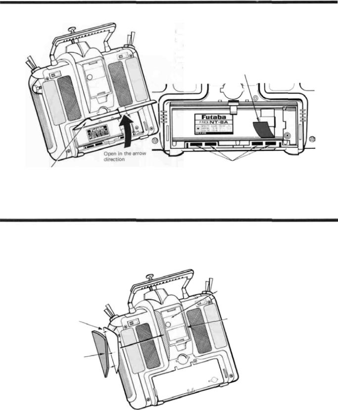
TRANSMITTER BATTERY REPLACEMENT
The transmitter battery is easily removed and replaced, making it simple to have a spare battery pack for extended flying duration.
Open the battery cover and remove the rechargeable battery pack by pulling outward on the ribbon. Be careful not to damage the battery cover or drop the battery pack.
Battery Cover
RUBBER PROTECTIVE PAD INSTALLATION
We recommend that rubber protection pads be installed in case the transmitter is ever rested on its back.
RFModule
Double-sided tape |
Repeat for other side. |
Stick the double-sided tape to the inside of the protection pad
Stick the protection pads to the shaded area of the transmitter.
Manual Introductory Section, Page 21

Manual Introductory Section
TRANSMITTER RF MODULE
The PCM 1024Z transmitter is designed to work with either the FP-TK-FM or the FP-TK-FSS fre- quency-synthesized Radio Frequency (RF) modules. Other modules may not be used.
It is normal for the module's temperature to rise during operation.
To remove the module, press inwards on the top and bottom tabs and simultaneously pull the module away from the rear of the transmitter.
OPTIONAL SYNTHESIZED FREQUENCY MODULE & RECEIVER
The R309DPS synthesized-frequency receiver and matching transmitter frequency module are supplied with the PCM1024ZAPS and PCM 1024ZHPS systems. The transmitting and receiving frequency may be easily changed without removing any crystals or exchanging frequency modules. The ability to rapidly change frequency is a great advantage on a crowded flying field or in contest entry.
The receiver will also work with any other Futaba 1024 systems. For more information on the synthesized system, refer to page 37.
CAUTION
If you are using the Synthesized transmitter module FP-TK-FSS, be sure that you know the transmitting frequency before switching on. If you don't know the frequency, hold the A or R key down as you switch on power. The transmitting frequency will be displayed but radio transmission is deactivated. Once you have determined the frequency, secure the appropriate frequency control device and turn on power to operate normally.
Manual Introductory Section, Page 22
 Loading...