


Futaba
DIGITAL PROPORTIONAL RADIO CONTROL
FP-7UAP
PCM 1024 SYSTEM
FP-7UAF
FM SYSTEM
D60460

Thank you for purchasing
a Futaba digital proportional radio control set. Please read this manual
carefully before using your set The last page of this manual
is a double foldout showing the name of each part of the transmitter.
Please open it when reading this manual.
foldout
• FEATURES
• High resolution and fast response |
PCM 1024 system (FP-7UAP) |
7 channels system |
|
FM system (FP-7UAF) |
|||
|
|
• RF module
•Trainer system
(Trainer cable optional)
Dual rate switch w/combination function
• |
Normal display mode |
||
• |
Error |
display |
mode |
• |
Edit |
display |
mode |
Liquid crystal panel displays all the information necessary in each display mode.
Six edit keys provide f o r easy data setting.
• Set data is not lost
even when the battery is changed.
• Complete mixing functions |
|
—Snap-roll! 4 channels |
—Elevator -> f l a p mixing |
—Flaperon & aileron differential |
-Programmable mixing 2 separate systems |
—Flap -> elevator mixing |
|

• TABLE OF CONTENTS
SET CONTENTS . . . . . . . . . . . . . . . . . . . . . . . . . . . . . . . . . . . . . . . . . . . 2 BEFORE USING . . . . . . . . . . . . . . . . . . . . . . . . . . . . . . . . . . . . . . . . . . 3-5
DISPLAY FUNCTIONS
NORMAL DISPLAY MODE . . . . . . . . . . . . . . . . . . . . . . . . . . . . . . 6 ERROR DISPLAY MODE . . . . . . . . . . . . . . . . . . . . . . . . . . . . . . . . 7 EDIT DISPLAY MODE . . . . . . . . . . . . . . . . . . . . . . . . . . . . . . . . . . 7
FUNCTIONS AND DATA SETTING |
|
ADJUSTABLE TRAVEL VOLUME . . . . . . . . . . . . . . . . . . . . . . |
. . 8 |
DUAL RATE . . . . . . . . . . . . . . . . . . . . . . . . . . . . . . . . . . . . . . . . |
. . 8 |
E X P O N E N T I A L . . . . . . . . . . . . . . . . . . . . . . . . . . . . . . . . . . . . . . . |
. 9 |
REVERSE . . . . . . . . . . . . . . . . . . . . . . . . . . . . . . . . . . . . . . . . . . . . |
9 |
FAIL SAFE . . . . . . . . . . . . . . . . . . . . . . . . . . . . . . . . . . . . . . . . . . . |
10 |
PROGRAMMABLE MIXING 1 . . . . . . . . . . . . . . . . . . . . . . . . . . . |
. 11 |
PROGRAMMABLE MIXING 2 . . . . . . . . . . . . . . . . . . . . . . . . . . . |
. 12 |
ELEVATOR -> FLAP MIXING . . . . . . . . . . . . . . . . . . . . . . . . . . . . |
13 |
FLAP -> ELEVATOR MIXING . . . . . . . . . . . . . . . . . . . . . . . . . . . . |
14 |
SNAP-ROLL . . . . . . . . . . . . . . . . . . . . . . . . . . . . . . . . . . . . . . . . . . |
15 |
AILERON DIFFERENTIAL . . . . . . . . . . . . . . . . . . . . . . . . . . . . . . |
16 |
FLAPERON . . . . . . . . . . . . . . . . . . . . . . . . . . . . . . . . . . . . . . . . . . |
. 17 |
FLAP TRIM . . . . . . . . . . . . . . . . . . . . . . . . . . . . . . . . . . . . . . . . . . |
. 18 |
SUB T R I M . . . . . . . . . . . . . . . . . . . . . . . . . . . . . . . . . . . . . . . . . . . . |
. 18 |
COMBINATION SWITCH . . . . . . . . . . . . . . . . . . . . . . . . . . . . . . . . |
18 |
MODULATION . . . . . . . . . . . . . . . . . . . . . . . . . . . . . . . . . . . . . . . . |
19 |
OTHER FUNCTIONS . . . . . . . . . . . . . . . . . . . . . . . . . . . . . . . . . . . . |
19-20 |
USING THE ACCESSORIES . . . . . . . . . . . . . . . . . . . . . . . . . . . . . . . |
20-21 |
NOMENCLATURE (DOUBLE FOLDOUT) . . . . . . . . . . . . . . . . . . . . . |
. 22 |
SERVO EXPLODED VIEW . . . . . . . . . . . . . . . . . . . . . . . . . . . . . . . . . . . |
23 |
ABBREVIATIONS |
|
|
|
|
ATV |
ADJUSTABLE TRAVEL |
FLPR |
FLAPERON |
|
|
VOLUME |
FLTR |
FLAP TRIM |
|
D/R |
DUAL RATE |
STRM |
SUB TRIM |
|
EXP |
EXPONENTIAL |
COMB |
COMBINATION |
SWITCH |
REV |
REVERSE |
MOD |
MODULATION |
|
F/S |
FAILSAFE |
AUX |
AUXILIARY |
|
PMX |
PROGRAMMABLE MIXING |
PCM |
PULSE CODE |
MODULATI |
2 - > 6 |
ELEVATOR^ FLAP MIXING |
PPM |
PULSE POSITION |
|
6 - > 2 |
FLAP -> ELEVATOR MIXING |
|
MODULATION |
|
SNP |
SNAP-ROLL |
B.F/S |
BATTERY FAIL SAFE |
|
DIFF |
AILERONDIFFERENTIAL |
|
|
|
— 1 —

• SET CONTENTS
*Specifications are subject to change without prior notice.
FP-7UAP |
FP-7UAF |
• FP-T7UAP ( X 1 ) |
• FP-T7UAF (X1) |
|
• FP-TP-FM (X1) |
• FP-R129DP (X1) |
• FP-R128DF ( X 1 ) |
(Dual Conversion Type) |
(Dual Conversion Type) |
or FP-R137GP (X1) |
|
•FP-S148 (X4)
or FP-S3001 (X4)
•NT-8LP(X1)
•NR-4J ( X 1 )
• Charger |
• Receiver switch |
• |
Servo horn |
|
|
• Servo tray |
|
|
|
• Tx hook band |
|
|
|
• |
Frequency flag |
|
|
|
or ribbon |
Rating
2 sticks, 7 channels, PCM or FM transmitter Transmitting frequency: 72MHz, 50MHz, 35/36MHz, 40/41 MHz or 29MHz band Modulation: FM-PCM/PPM Selectable Power requirement: 9.6V Nicd battery pack Current drain: 200mA
Receiving frequency: 72MHz, 50MHz, 35/36MHz, 40/41 MHz or 29MHz band Intermediate frequency: 1st IF 10.7MHz, 2nd IF 455kHz (R129DP, R128DF), 455kHz (R137GP)
Power requirement; 4.8V Nicd battery pack (shared with servo)
Current drain: 35mA (R129DP), 26mA (R128DF), 25mA (R137GP)
Dimensions: 63.0x37.8x24.1mm (R129DP). 63.8x35.4x20.3mm (R128DF) (excluding protruding parts), 57x42x24mm (R137GP) Weight: 45g (R129DP),40g (R128DF), 45g(R137GP)
Receiving range: 500m on the ground. 1000m in the air (range differs with the surroundings]
Control system: + pulse width control Operating angle: Rotary system, one side 45 or greater (including trim)
Power requirement: 4.8V or 6.0V (shared with receiver)
Current drain: 8mA at 6V (at idle) Output torque; 3kg/cm
Operating speed; 0.22sec/60° Dimensions: 40.4x1 9.8x36mm Weight: 44.4g, 1.56oz. (S148), 45.1q, 1.59oz. (S3001)
Voltage: 9.6V
Capacity: 800mAh
Voltage: 4.8V
Capacity: 500mAh
Dimensions: 51x58x1 5mm
Weight: 95g,3.35oz.
•FM crystal set (Transmitter and Receiver)
However use the following crystal types for dual conversion receiver (R129DP, R128DF).
The set does not include the following:
• Trainer cable (6-conductor)
- 2 -

• BEFORE USING
• Charging the transmitter and receiver Nicd battery
FP-7UAPor FP-7UAF
Charger
LED
Power plug
Tx |
side |
Rx side |
(NT-8LP inside) |
|
|
Male |
|
Female |
Remove the charging cap |
|
and connect the charger. |
|
Receiver |
|
Nicd battery NR-4J |
• Factory setting of transmitter modulation system
The transmitter modulation system (PCM/PPM mode) is switched by
data setting. (For the setting method, see P19.). However, it is set as
follows at the factory:
FP-T7UAP . . . . . |
PCM mode |
FP-T7UAF . . . . . |
PPM mode |
Refer to only the necessary items of the items enclosed in
*Use the special Futaba charger.
• The charging time is 15 hours.
[However when the battery was not used for some time, charge and discharge it 2 — 3 times. Otherwise, the battery will not be charged even after the specified charging time !
A fully-charged transmitter battery can be used for about 10 flights of 10 minutes each. The airborne NR4J Nicd battery pack can be used for about 6 flights when 6 servos are used.
Notes: (PBC-8B)
1)First, connect to TX Nicad and red lamp goes on.
2)Then, connect to RX Nicad after connecting, L, E, D, changes color from red to greenish red (orange) which indicates that both TX and RX Nicads are being charged.
3)In case of separate charging, L, E, D, color will be:
RX Nicad - Green TX NicadRed
• Changing the transmitter Nicd battery pack |
• Changing the RF module to change the |
|
frequency band |
Remove the battery cover. |
1 Remove the RF module. |
Pull the RF module forward while pressing these tabs to the inside
Battery cover
2 Change the Nicd battery.
® side contact
-Nicd battery (Only the NT-8LP can be used.)
*Load the battery while paying careful attention to the direction of the contacts.
2 Change the RF module.
Push in the new module, while being careful not to bend the pins, until the tabs at both sides lock into place with a "click".
*Use the special FP-TP-FM RF module for the FP7UAP and 7UAF. Other RF modules cannot be used.
•When the transmitter frequency band is changed, the receiver frequency band must be changed also.
— 3 —

•BEFORE USING
•RECEIVER AND SERVO CONNECTIONS
Pay careful attention to the polarity of the connector.
Antenna
wire
PCM receiver
FP-R129DP, FP-R137GPor
FM receiver FP-R-128DF
Extension cord
Receiver switch
Charging jack
CH7 (AUX)
CH6 Flap servo Option
(sold separately)
CH5 Landing gear servo
CH4
Rudder servo
|
CH3 |
|
|
Throttle |
Four servos |
|
servo |
|
|
are supplied |
|
|
|
|
|
CH2 |
as standard. |
|
Elevator |
|
|
servo |
|
|
CH1 |
|
|
Aileron |
|
|
servo |
|
Receiver connector arrangement |
||
FP-R137GP |
FP-R129DP |
FP-R128DF |
Nicd battery pack
NR-4J
PRECAUTIONS
•Connect the receiver, servos, switches, and battery as shown in the figure. Extend the trans-
mitter and receiver antennas to their full length.
•Turn on the transmitter power switch, then turn on the receiver power switch.
The servos will go to their neutral position. Move the transmitter sticks one at a time to check that each servo follows its control stick movement.
•Connect the pushrods to the servos and check that the direction of travel of each servo matches the direction of movement of its control stick. If a servo does not move in the proper direction, switch its direction with the servo reversing function.
•Operate each servo horn over its full stroke and check that the pushrod does not bind or is not too loose. Unreasonable force applied to the servo horn will adversely affect the servo and
- 4 -
• BEFORE USING
drain the battery pack very quickly. Make the travel of each control mechanism somewhat larger than the full stroke (including trim) of the servo horn. Adjust the servo horns so that they move smoothly even when the trim lever and stick are operated simultaneously in the same direction.
• Be alert for noise.
This set is noise-resistant, but not completely immune to noise. The use of noiseless parts is recommended.
•When installing the switch harness, cut a rectangular hole slightly larger than the full stroke of the switch and install the switch so that it moves smoothly from ON to OFF. Also do this when the switch is installed inside the fuselage and is turned on and off from the outside with a piece of wire. Install the switch where it will not be exposed to engine oil or dust and dirt.
•Although the antenna appears to be too long, do not cut it or fold it back.
•Install the servos securely. Tighten the mounting screws until the rubber damper is crushed slightly. If the screws are too tight, the cushioning effect will be adversely effected.
SERVO HORN MOUNTING SCREW PRECAUTIONS
Servohornscrews
Horn |
|
|
|
Dimen- |
|
mounting |
|
Applicable servo |
Type |
sions |
|
screw size |
|
|
|
(m/m) |
|
|
|
|
|
|
|
2.6x6 |
S133, |
S143 series |
B |
5.7 |
|
|
|
|
|
||
|
S 129 series |
A |
7.9 |
||
|
S130 series, S9101, S5101 |
A |
7.9 |
||
|
|
|
|
|
|
|
S128 |
series |
B |
11.9 |
|
2.6x8 |
S132 |
series |
B |
7.3 |
|
|
S135 series, S9601 |
B |
8.7 |
||
|
|
|
|
||
|
S136G |
A |
9.0 |
||
|
S138 |
series |
B |
9.9 |
|
|
S148 |
series |
B |
10.5 |
|
|
|
|
|
||
2.6x10 |
S131S series, S9201,S9301 |
A |
9.0 |
||
89401 |
|||||
|
|
|
|||
|
|
|
|
||
2.6x12 |
8134 series, 83301 |
A |
11.3 |
||
|
|
|
|
|
|
•The crystal can be changed from the outside of the receiver case. Always use the Futaba trans-
mitter/receiver matched crystal set to change the band.
•The receiver that is used with the 7UAP and 7UAF is a dual conversion receiver. This receivers requires a special crystal so please order the correct crystal set.
•Spare servo horns are supplied. Use them as needed.
•Use extension cords matched to the model.
•Wrap the receiver in sponge rubber. Place it inside a waterproof plastic bag and secure the end of the bag with a rubber band. Do the same with the airborne battery pack.
•Use the rubber bands wrapped around the receiver to hold the servo and switch leads.
•After installation and checking are complete, perform a range check by collapsing the transmitter antenna and extending the receiver antenna to its full length and operating the transmitter from a distance of 20 to 30 meters from the receiver. The servos should operate normally at this distance.
•Differs with the weather and surroundings.
Horn |
Horn |
Waterproof type A |
Non-waterproof type B |
Notes
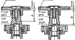
•The screws are 2.6m/m tapping screws.
•If screws longer than necessary are used, the final gear may be broken or the potentiometer may be damaged or
may fall out.
-5-

• DISPLAY FUNCTION
Liquid crystal panel
• Operated in three display modes
EDIT KEY
MODE SELECT |
CURSOR |
DATA INPUT |
• Used in display mode switching. |
|
|
• Used in setting function selection |
|
• Used at data setting. |
Display
Display mode at_normal use (Mode which is displayed when the power switch is turned on.)
(Display)
Battery voltage display
•Reverse function display (N: Normal, R: Reverse)
•PCM/PPM mode display
(PCM: PCM mode, PPM: PPM mode)
• Integrated time display ( 0 — 1 9 9 minutes)
(Displays the integrated time after reset.) |
|
Clock reset |
|
Reset by pressing the |
keys |
simultaneously. |
|
• Flashes at a 1 second period |
Error |
• F/S data transfer display (FP-7UAP only) |
|
(Lights momentarily each minute) |
|
• RF indicator |
|
(Lights when radiowaves are transmitted.) |
|
• Mixing indicator
(Flashes when snap roll mixing or 6 -> 2 mixing is ON.)
— 6 —
 Loading...