


14MZ
14 CHANNEL RADIO CONTROL SYSTEM PCMG3/PCM1024/FM selectable
INSTRUCTION MANUAL
Entire Contents © Copyright 2005
1M23N14802

TABLE OF CONTENTS |
|
INTRODUCTION .............................................. |
4 |
●Support and Service ......................................... |
4 |
●Application, Export, and Modification........... |
5 |
●Definitions of Symbols...................................... |
6 |
●Safety Precautions (do not operate without |
|
reading) ............................................................. |
6 |
BEFORE USE ..................................................... |
9 |
●Features of 14MZ ............................................. |
9 |
●Contents and technical specifications ........... |
11 |
●Accessories....................................................... |
12 |
●Transmitter controls....................................... |
13 |
Cautions on handling antenna .......................... |
13 |
LED monitor .................................................... |
14 |
Switch reallocation (SA-SH) ........................... |
14 |
Volume (LD, CD, RD) ..................................... |
15 |
Slide Lever (LST, LS, RS, RST)...................... |
15 |
Digital trim (T1-T6) ......................................... |
16 |
Touch panel/Rotary key/Direct key ................. |
16 |
Stick Adjustment .............................................. |
17 |
CF card CFDP32M .......................................... |
18 |
Connector/Plug................................................. |
19 |
USB port (*This port is for factory use only.)................. |
19 |
Attachment and detachment of the battery ...... |
20 |
RF module MZ-FM.......................................... |
21 |
Toolbox ............................................................ |
21 |
●Receiver nomenclature................................... |
22 |
●Safety precautions when installing receiver and |
|
servos ............................................................... |
23 |
BASIC OPERATION ....................................... |
24 |
●Battery Charging............................................ |
24 |
How to charge the Lithium Ion Battery ........... |
24 |
How to charge the Ni-Cd Battery..................... |
24 |
●How to turn On/OFF the transmitter ........... |
25 |
When turning on............................................... |
25 |
When turning off .............................................. |
25 |
How to reset ..................................................... |
26 |
●How to change the frequency/How to set the |
|
receiver's ID.................................................... |
26 |
2 TABLE OF CONTENTS |
|
●In case of using PCM1024, PPM receivers... |
27 |
●Registration of the user's name..................... |
27 |
●Home screen .................................................... |
28 |
●Music play back .............................................. |
29 |
FUNCTIONS OF SYSTEM MENU................ |
30 |
Trainer .............................................................. |
31 |
Display ............................................................. |
33 |
Date & Time..................................................... |
34 |
User Name........................................................ |
35 |
Switch............................................................... |
36 |
HW Reverse ..................................................... |
37 |
Information ...................................................... |
38 |
MODEL BASIC SETTING PROCEDURE ... |
39 |
●Airplane/glider basic setting procedure........ |
39 |
●Helicopter basic setting procedure................ |
41 |
●Receiver and servos connection..................... |
45 |
●Servo connection by model type.................... |
46 |
FUNCTIONS OF LINKAGE MENU ............. |
50 |
(Common Functions) |
|
Linkage Menu functions table.......................... |
50 |
Servo Monitor .................................................. |
51 |
Model Select .................................................... |
52 |
Model Type ...................................................... |
53 |
Picture .............................................................. |
55 |
Sound ............................................................... |
56 |
Frequency......................................................... |
58 |
Function ........................................................... |
59 |
Sub-Trim .......................................................... |
61 |
Servo Reverse .................................................. |
62 |
Fail Safe ........................................................... |
63 |
End Point (ATV) .............................................. |
64 |
Throttle Cut (Airplane/helicopter only) ........... |
65 |
Idle Down (Airplane/helicopter only).............. |
66 |
Swash (Helicopter only)................................... |
67 |
Timer ................................................................ |
69 |
Dial Monitor..................................................... |
70 |
Data Reset ........................................................ |
71 |

FUNCTIONS OF MODEL MENU |
|
●Common Functions ........................................ |
72 |
Servo Monitor (Linkage Menu 51) |
|
Condition Select............................................... |
73 |
Condition Hold................................................. |
74 |
AFR (D/R)........................................................ |
75 |
Program Mix .................................................... |
77 |
Fuel Mixture..................................................... |
79 |
●Airplane/Glider/EP Glider Functions........... |
80 |
Model Menu functions list ............................... |
80 |
AIL Differential................................................ |
82 |
Flap Setting ...................................................... |
83 |
AIL to Camber FLP.......................................... |
84 |
AIL to Brake FLP............................................. |
85 |
AIL to RUD...................................................... |
86 |
Airbrake to ELE ............................................... |
87 |
RUD to AIL...................................................... |
88 |
Camber Mix ..................................................... |
89 |
ELE to Camber................................................. |
91 |
Camber FLP to ELE......................................... |
92 |
Butterfly ........................................................... |
95 |
Trim Mix 1/2 .................................................... |
95 |
Airbrake ........................................................... |
97 |
Gyro ................................................................. |
99 |
V-tail............................................................... |
100 |
Ailevator......................................................... |
101 |
Winglet........................................................... |
102 |
Motor.............................................................. |
103 |
RUD to ELE................................................... |
104 |
Snap Roll........................................................ |
105 |
Multi Engine .................................................. |
106 |
●Helicopter Functions .................................... |
107 |
Model Menu functions list ............................. |
107 |
PIT Curve....................................................... |
108 |
THR Curve..................................................... |
111 |
Acceleration ................................................... |
113 |
Throttle Hold.................................................. |
114 |
Swash Mix...................................................... |
115 |
Throttle Mix ................................................... |
116 |
PIT -> Needle................................................. |
117 |
PIT -> RUD.................................................... |
118 |
Gyro ............................................................... |
119 |
Governor ........................................................ |
120 |
●Common Operations used in function setup |
|
screen............................................................. |
121 |
TABLE OF CONTENTS 3
INTRODUCTION
Thank you for purchasing the Futaba® 14MZ series digital proportional R/C system. In order for you to make the best use of your system and to fly safely, please read this manual carefully. If you have any difficulties while using your system, please consult the manual, our online Frequently Asked Questions (on the web pages referenced below), your hobby dealer, or the Futaba Service Center.
Due to unforeseen changes in production procedures, the information contained in this manual is subject to change without notice.
Support and Service: It is recommended to have your Futaba equipment serviced annually during your hobby’s “off season” to ensure safe operation.
IN NORTH AMERICA
Please feel free to contact the Futaba Service Center for assistance in operation, use and programming. Please be sure to regularly visit the 14MZ Frequently Asked Questions web site at http://www.futaba-rc.com/faq/faq/index.html. This page includes extensive programming, use, set up and safety information on the 14MZ radio system and is updated regularly. Any technical updates and US manual corrections will be available on this web page. If you do not find the answers to your questions there, please see the end of our F.A.Q. area for information on contacting us via email for the most rapid and convenient response.
Don’t have Internet access? Internet access is available at no charge at most public libraries, schools, and other public resources. We find internet support to be a fabulous reference for many modelers as items can be printed and saved for future reference, and can be accessed at any hour of the day, night, weekend or holiday. If you do not wish to access the internet for information, however, don’t worry. Our support teams are available Monday through Friday 8-5 Central time to assist you.
FOR SERVICE ONLY |
FOR SUPPORT |
Futaba Service Center |
(PROGRAMMING AND USER QUESTIONS) |
3002 N. Apollo Drive, Suite 1 |
Please start here for answers to most questions: |
Champaign, IL 61822 |
www.futaba-rc.com |
Phone: 217-398-0007 |
FACSIMILE: 217-398-7721 |
www.hobbyservices.com |
PHONE: 217-398-8970 option 2 |
OUTSIDE NORTH AMERICA
Please contact your Futaba importer in your region of the world to assist you with any questions, problems or service needs. Please recognize that all information in this manual, and all support availability, is based upon the systems sold in North America only. Products purchased elsewhere may vary. Always contact your region’s support center for assistance.

Application, Export, and Modification
1.This product is suitable for model airplane, surface or 50 MHz (license required) use, if on the correct frequency. It is not intended for use in any application other than the control of models for hobby and recreational purposes. The product is subject to regulations of the FCC and is restricted under United States law to such purposes.
2.Exportation precautions:
(a)When this product is exported from the country of manufacture, its use is to be approved by the laws governing the country of destination which govern devices that emit radio frequencies. If this product is then re-exported to other countries, it may be subject to restrictions on such export. Prior approval of the appropriate government authorities may be required. If you have purchased this product from an exporter outside your own country and not the authorized Futaba distributor in your country, please contact the seller immediately to determine if such export regulations have been met.
(b)Use of this product with other than models may be restricted by Export and Trade Control Regulations, and an application for export approval must be submitted. In the US, use of 72MHz (aircraft only), 75MHz (ground models only) and 27MHz (both) frequency bands are strictly regulated by the FCC. This equipment must not be utilized to operate equipment other than radio controlled models. Similarly, other frequencies (except 50MHz, for HAM operators) must not be used to operate models.
3. Modification, adjustment, and replacement of parts: Futaba is not responsible for unauthorized modification, adjustment, and replacement of parts on this product. Any such changes may void the warranty.
The Following Statement Applies to the Receiver (for U.S.A.)
This device complies with part 15 of the FCC rules. Operation is subject to the following two conditions:
(1)This device may not cause harmful interference.
(2)This device must accept any interference received, including interference that may cause undesirable operation.
The RBRC™ SEAL on the nickel-cadmium battery contained in Futaba products indicates that Futaba Corporation of America is voluntarily participating in an industry-wide program to collect and recycle these batteries at the end of their useful lives, when taken out of service within the United States. The RBRC program provides a convenient alternative to placing used nickel-cadmium batteries into the trash or municipal waste system, which is illegal in most areas.
You may contact your local recycling center for information on where to return the spent battery. Please call 1-800-8-BAT- TERY for information on battery recycling in your area. Futaba Corporation of America’s involvement in this program is part of it’s’ commitment to protecting our environment and conserving natural resources.
NOTE: Our instruction manuals encourage our customers to return spent batteries to a local recycling center in order to keep a healthy environment. RBRC is a trademark of the Rechargeable Battery Recycling Corporation.

Definitions of Symbols
Pay special attention to safety where indicated by the following symbols.
 DANGER – Procedures which may lead to dangerous conditions and cause death/serious injury if not carried out properly.
 WARNING – Procedures which may lead to a dangerous condition or cause death or serious injury to the user if not carried out properly, or procedures where the probability of superficial injury or physical damage is high.
 CAUTION – Procedures where the possibility of serious injury to the user is small, but there is a danger of injury, or physical damage, if not carried out properly.
= Prohibited |
= Mandatory |
Warning: Always keep electrical components away from small children.
FLYING SAFETY
To ensure the safety of yourself and others, please observe the following precautions:
 Have regular maintenance performed. Although your 14MZ protects the model memories with non-volatile EEPROM memory (which does not require periodic replacement) and not a battery, it still should have regular checkups. We recommend sending your system to the Futaba Service Center annually during your non-flying season for a complete checkup and service.
 Use the Fail-Safe safety feature to set the throttle to low-idle In case of signal loss or RX battery failure.
Engine power will be automatically reduced to help limit personal or property damage. Refer to the Failsafe Setting Procedure listed in the index.
Receiver Ni-Cd Battery
 Charge the batteries! (See Charging the batteries listed in the index for details.) Always recharge the receiver batteries for at least 8 hours before each flying session. A low battery will soon die, causing loss of control and a crash. When you begin your flying session, reset your timer, and during the session pay attention to the duration of usage.
CAUTION: The initial charge on new NiCd receiver batteries should be done for 15 hours using the slow-charger that came with the radio system. This will “condition” the batteries so that the next charge may be done using the fast-charger of your choice. If the initial charge is done with a fast-charger the batteries may not reach their full capacity and you may be flying with batteries that are only partially charged.
Where to Fly
We recommend that you fly at a recognized model airplane flying field. You can find model clubs and fields by asking your nearest hobby dealer, or in the US by contacting the Academy of Model Aeronautics. You can also contact the national Academy of Model Aeronautics (AMA), which has more than 2,500 chartered clubs across the country. Through any one of them, instructor training programs and insured newcomer training are available. Contact the AMA at the address or toll-free phone number below.
Academy of Model Aeronautics
5151 East Memorial Drive
Muncie, IN 47302-9252
Tel. (800) 435-9262
Fax (765) 741-0057
or via the Internet at http:\\www.modelaircraft.org

Lithium-ION Battery Safety and Handling instructions
IMPORTANT! The Lithium-Ion (Li-Ion) batteries included in the 14MZ transmitter are not to be confused with Lithium-Polymer (LiPo) batteries, or any other type of rechargeable battery (including NiCd’s and NiMH’s). Li-Ion batteries require special charging criteria different than other rechargeable batteries. Use only the Futaba lithium ion transmitter charger included with this set for, or other chargers approved by Futaba to charge the Li-Ion batteries in the 14MZ transmitter.
It is important to understand the operating characteristics of lithium-ion (Li-Ion) batteries. Always read the specifications printed on the label of your Li-Ion battery and charger prior to use. Failure to follow the proceeding precautions can quickly result in severe, permanent damage to the batteries and its surroundings and possibly result in a FIRE!
IMPORTANT PRECAUTIONS
 Do not attempt to disassemble Li-Ion packs or cells.
 Do not allow Li-Ion cells to come in contact with moisture or water at any time.
Always provide adequate ventilation around Li-Ion batteries during charge, discharge, while in use, and during storage.
Do not leave a Li-Ion battery unattended at any time while being charged or discharged.
Do not attempt to charge Li-Ion batteries with a charger that is NOT designed for Li-Ion batteries, as permanent damage to the battery and charger could result.
Always charge Li-Ion batteries in a fireproof location. Do not charge or discharge Li-Ion batteries on carpet, a cluttered workbench, near paper, plastic, vinyl, leather or wood, or inside an R/C model or full sized automobile! Monitor the charge area with a smoke or fire alarm, and have a lithium-approved “ABC type” fire extinguisher available at all times.
Do not charge Li-Ion batteries at currents greater than the “1C” rating of the battery (“C” equals the rated capacity of the battery).
Do not allow Li-Ion cells to overheat at any time! Cells which reach greater than 140 degrees Fahrenheit (60oC) should be placed in a fireproof location.
It is normal for the batteries to become warm during charging, but if the charger or battery becomes excessively hot disconnect the battery from the charger immediately!! Always inspect a battery which has previously overheated for potential damage, and do not re-use if you suspect it has been damaged in any way.
Do not use a Li-Ion battery if you suspect physical damage has occurred to the pack. Carefully inspect the battery for even the smallest of dents, cracks, splits, punctures or damage to the wiring and connectors. DO NOT allow the battery’s internal electrolyte to get into eyes or on skin—wash affected areas immediately if they come in contact with the electrolyte. If in doubt, place the battery in a fire-proof location for at least 30 minutes.
Do not store batteries near an open flame or heater.
Do not discharge Li-Ion batteries at currents which exceed the discharge current rating of the battery.
Always store Li-Ion cells/packs in a secure location away from children.
Compact Flash (CF) Card Handling Instructions
Follow these precautions when handling the CF card included in your 14MZ transmitter.
Never remove the CF card or turn off power while entering data.
Never store the CF card where it may be subject to strong static electricity or magnetic fields.
Do not expose the CF card to direct sunlight, excessive humidity or corrosive environments.
Do not expose the CF card to dirt, moisture, water or fluids of any kind.
Always hold the CF card by the edges during installation and removal.
 Be certain to insert the CF card in the correct direction.

AT THE FLYING FIELD
 Always pay particular attention to the flying fields’ rules, as well as the presence and location of spectators, the wind direction, and any obstacles on the field. Be very careful flying in areas near power lines, tall buildings, or communication facilities as there may be radio interference in their vicinity. If you must fly away from a club field, be sure there are no other modelers flying within a three-to-five-mile range, or you may lose control of your aircraft or cause someone else to lose control.
 Before flying, be sure that the frequency you intend to fly with is not in use, and secure any frequency control device (pin, tag, etc.) for that frequency before turning on your transmitter. It is never possible to fly two or more models on the same frequency at the same time. Even though there are different types of modulation (AM, FM, PCM), only one model may be flown on a single frequency at any one time.
 Stop flying long before your batteries become low on charge. Do not rely on your radio’s low-battery warning systems, which are intended only as a precaution, to tell you when to recharge. Always check your transmitter and receiver batteries prior to each flight.
 To prevent possible damage to your radio gear, turn the power switches on and off in the proper sequence:
1.Set the throttle stick to the idle position, or otherwise disarm your motor/engine.
2.Fully extend the transmitter antenna.
3.Turn on the transmitter power and allow your transmitter to reach its home screen.
4.Confirm the proper model memory has been selected.
5.Turn on your receiver power.
6.Test all controls. If a servo operates abnormally, don’t attempt to fly until you determine the cause of the problem. (For PCM systems only: Test to ensure that the Failsafe settings are correct by waiting at least 2 minutes after adjusting then, turning the transmitter off and confirming the proper surface/throttle movements. Turn the transmitter back on.)
7.Start your engine.
8.Complete a full range check.
9.After flying, bring your throttle stick to idle position, engage any kill switches or otherwise disarm your motor/engine.
10.Turn off receiver power.
11.Turn off transmitter power.
If you do not turn on your system in this order, you may damage your servos or control surfaces, flood your engine, or in the case of electric-powered or gasoline-powered models, the engine may unexpectedly turn on and cause a severe injury.
 While you are getting ready to fly, if you place your transmitter on the ground, be sure that the wind won’t tip it over. If it is knocked over, the throttle stick may be accidentally moved, causing the engine to speed up. Also, damage to your transmitter may occur.
 Before taxiing, be sure to extend the transmitter antenna to its’ full length. A collapsed antenna will reduce your flying range and cause a loss of control. It is a good idea to avoid pointing the transmitter antenna directly at the model, since the signal is weakest in that direction.
 Don’t fly in the rain! Water or moisture may enter the transmitter through the antenna or stick openings and cause erratic operation or loss of control. If you must fly in wet weather during a contest, be sure to cover your transmitter with a waterproof barrier. Never fly if lightning is expected.
 Never turn the transmitter off during flight! Switching the transmitter off and on during flight will very likely cause a crash because of the time required for the transmitter to "reboot" and become fully functional.

BEFORE USE
FEATURES
PCMG3 (PCM Generation 3)
PCMG3 has a 40% faster response than current PCM1024. The resolution is 2048, which is double the current PCM1024. It can operate up to 14 Channels. The multi-level modulation technology has been implemented for the R/C industry to achieve the highest performance available today.
WindowsCE
T14MZ utilizes the world famous Microsoft WindowsCE, which offers outstanding dependability and valuable resources.
Color LCD
T14MZ has a HVGA (640x240 pixels) wide screen full color LCD. It has a backlight and the screen is manufactured of a transflective construction which enables both indoor and outdoor visibility.
Music Play
T14MZ can playback WMA (Windows Media Audio) files on a CF-Card. You can enjoy music by the internal speaker or stereo headphone from the earphone jack, and you can assign switches to start/stop your music. You can download the WMA files of your own music from your PC.
Voice Recording
You can record your own voice by internal microphone and then play back commands to be assigned to certain switches. Recording time is 3 seconds maximum and 24 voice files can be stored.
Picture Image Pasting
You can paste picture image files (168x80 pixels) taken by digital camera to the model screen. Enabling you to download any image you like on your home screen.
Compact Flash
The model data and music files, voice files, picture image files are stored to Compact flash (CF) card. The memory size is 32 MB. Futaba prepares industrial rating CF cards.
WFSS (Wireless Frequency Setting System)
The construction of both transmitter (T14MZ) and receiver (R5014) are a frequency synthesizer system.
Editing
The touch panel and rotary encoder editing system will allow you to edit your model in the manner that is easiest and most functional for you.
Functions
The internal dual processors operate the many 14MZ FEATURE functions and optimize the response time. Most of the mixing functions are operated by curves which give you more precise settings.
<Before Use> 9

Stick
Each axis is supported by dual ball bearings. This allows for finer and more precise operation, the new potentiometers also offer longer life.
Replaceable switches
You can replace 8 of the toggle switches on the right and left shoulder, with optional switches (two position, three position, and momentary etc.).
Li-ion battery
T14MZ is operated by 7.4V/2,200 mAh Lithium-Ion battery.
R5014DPS
The R5014DPS is a small 14CH synthesized receiver with high sensitivity and selectability.
10 <Before Use>
Contents and Technical Specifications
(Specifications and ratings are subject to change without notice.)
Your 14MZAP or 14MZHP (packaged with a 14-channel PCM-G3 receiver) includes the following components:
•T14MZ Transmitter, including RF module (MZ-DDS)
•R5014 Receiver
•CFDP32M Data-Pack (CF card)
•LT2F2200 Li-ion battery & LBC-1D5 Charger
•NR4F1500 Ni-Cd battery & 110V wall charger (North America)
•Switch harness/Aileron extension cord/Y-harness/DSC cord
•Tool Box (includes special jig for adjustment)
•Neck strap
•Frequency Flag
The set contents depend on the type of set.
Transmitter T14MZAP/HP
Operating system: 2-stick, 14 channels, PCM-G3, synthesizer system
Transmitting frequency: US only 72 or 50 MHz bands
Modulation: PCM - G3, PCM1024, or FM/PPM switchable.
Power supply: 7.4V LT2F2200 Li-ion battery
Current drain: 1 ampere maximum (RF power on and back light on) 700mA average
Receiver R5014DPS
(PCM-G3, Synthesizer, Dual conversion)
Receiving frequency: US only 72 or 50 MHz bands Intermediate freq.: 10.7 MHz & 450 kHz
Power requirement: 4.8 V Ni-Cd battery Current drain: 75 mA
Size: 52x37.5x16.5 mm Weight: 33 g. Channels: 14
Suggested Servos for use with your 14MZ Servo S9154 (Digital servo)
Control system: Pulse width control, 1.52 ms neutral Power requirement: 4.8 V (from receiver)
Output torque: 63.9 oz.-in. (4.6 kg-cm) at 4.8V Operating speed: 0.14 sec/60 at 4.8V
Size: 1.87 x 1.06 x 0.97 in. (47.5 x 27.0 x 25.3 mm) Weight: 1.87 oz. (53 g)
Servo S9151 (Digital servo)
Control system: Pulse width control, 1.52 ms neutral Power requirement: 4.8 V (from receiver)
Output torque: 131.9 oz.-in. (9.5 kg-cm) at 4.8V Operating speed: 0.19 sec/60 at 4.8V
Size: 1.57 x 0.79 x 1.44 in. (40.0 x 20.0 x 36.6 mm) Weight: 1.79 oz. (50 g)
Servo S9250 (Digital servo)
Control system: Pulse width control, 1.52 ms neutral Power requirement: 4.8 V (from receiver)
Output torque: 76.4 oz.-in. (5.5 kg-cm) at 4.8V Operating speed: 0.11 sec/60 at 4.8V
Size: 1.59 x 0.79 x 1.48 in. (40.5 x 20.0 x 37.5 mm) Weight: 1.90 oz. (54 g)
Servo S9255 (Digital servo)
Control system: Pulse width control, 1.52 ms neutral Power requirement: 4.8 V (from receiver)
Output torque: 125.0 oz.-in. (9.0 kg-cm) at 4.8V Operating speed: 0.16 sec/60 at 4.8V
Size: 1.57 x 0.79 x 1.44 in. (40.0 x 20.0 x 36.6 mm) Weight: 1.94 oz. (55 g)
<Before Use> 11

The following additional accessories are available from your dealer. Refer to a Futaba catalog for more information:
•Compact Flash Memory card - CFDP 32M Data-Pack increases your model, music file, voice file, and picture image file storage capability, and allows you to transfer model settings to another T14MZ transmitter.
•LT2F2200 Transmitter battery pack - the (2200mAh) transmitter Li-ion battery pack may be easily exchanged with a fresh one to provide enough capacity for extended flying sessions.
•Trainer cord - the optional training cord may be used to help a beginning pilot learn to fly easily by placing the instructor on a separate transmitter. Note that the T14MZ transmitter may be connected to another T14MZ system, as well as to any other models of Futaba transmitters. The T14MZ transmitter uses the newer “Micro” rectangular type cord plug. Both Micro- to-Micro and Micro-to-round plug style trainer cords are available.
•Neckstrap - a neckstrap may be connected to your T14MZ system to make it easier to handle and improve your flying precision since your hands won’t need to support the transmitter’s weight.
•Y-harnesses, servo extensions, etc - Genuine Futaba extensions and Y-harnesses, including a heavy-duty version with heavier wire, are available to aid in your larger model and other installations.
•Gyros - a variety of genuine Futaba gyros are available for your aircraft or helicopter needs.
•Governor (GV1) - for helicopter use. Automatically adjusts throttle servo position to maintain a constant head speed regardless of blade pitch, load, weather, etc.
•DSC Cord - allows setup and testing without transmitting. With your Transmitter and Receiver off, plug cord into trainer port then, into the receiver Battery/DSC (B/C) slot. All programming and setup may be done in this manner without transmitting.
•Receivers - various models of Futaba receivers may be purchased for use in other models. (Receivers for PCM-G3, PCM1024, or FM/PPM types are available.)
12 <Before Use>

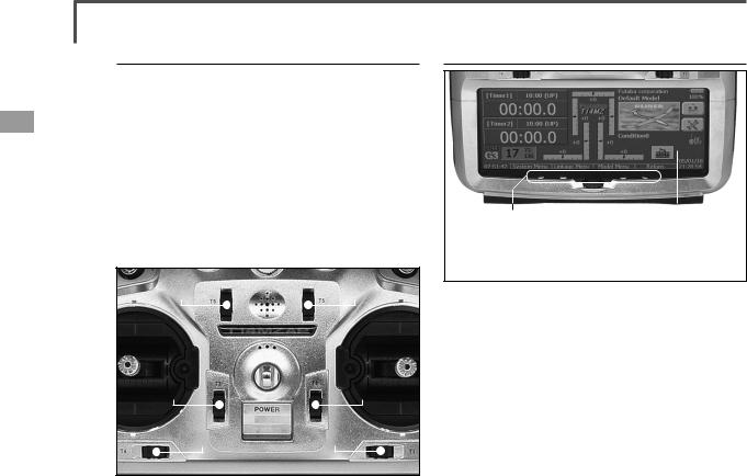
Transmitter controls
(LD,CD,RD) |
●Monitor LED |
●Antenna |
|
|
|||
●Carring Bar |
|
||
●Volume |
|
||
●Speaker |
|
||
|
|
|
|
|
|
●Microphone |
|
●Switch Block |
|
●Switch Block |
|
(SA,SB,SE,SF) |
|
(SC,SD,SG,SH) |
|
●Slide |
●Slide Lever |
|
Lever |
||
(RST,RS) |
||
(LS,LST) |
||
|
||
●Stick |
●Stick |
|
(J3) |
(J2) |
|
|
||
(J4) |
(J1) |
|
|
●Digital Trim
(T1-T6)
●Hook
●Power
Switch
●Direct Key |
●Rotary Key |
●LCD Display (Touch Panel) |
(S1-S4) |
|
|
Cautions on handling antenna
 WARNING
 Be sure to attach the antenna before operation.
*Antenna is stored in the antenna storage box in the transmitter.
 Never hold the antenna alone.
*Hold the carrying bar, otherwise the main body can be damaged.
Extend the antenna to the full extent, and make sure that the antenna is securely locked before
operation.
<Before Use> 13

•Antenna storage
When you store the transmitter in the carrying case, detach the antenna and store it in the antenna compartment in the transmitter.
●Antenna Compartment
Cover
•Angle adjustment of the antenna
You can change the angle of the antenna, as you like. Use 2.5mm hexagonal wrench to turn counterclockwise to release the screw on the left of the antenna holder, and change the angle of the antenna, as you like, then retighten.
●Screw
LED monitor
The color of the FUTABA logo mark shows the status of the transmitter.
(LED Display)
•When you turn on the transmitter, FUTABA logo shows different colors, and then the color stays constantly pink. The FUTABA logo blinks green very rapidly while internal processing is carried out after the power is turned on. Once the internal processing is over, the logo turns to pink color.
•The FUTABA logo turns on blue when you use DSC cable, or when no is selected for transmit. when the trainer function is set at student's side.
•The FUTABA logo blinks red slowly when you attach the RF module that is different from the setting.
•Under the normal usage (, that is, radio wave is being emitted), the FUTABA logo turns on green.
Switch reallocation
You can reallocate the toggle switches on the shoulders of the transmitter, as you like.
(Default settings)
• SA |
: 3 positions; Alternate; Short lever |
• SB |
: 3 positions; Alternate; Long lever |
• SC |
: 3 positions; Alternate; Long lever |
• SD |
: 3 positions; Alternate; Short lever |
• SE |
: 3 positions; Alternate; Short lever |
• SF |
: 2 positions; Alternate; Long lever |
• SG |
: 2 positions; Alternate; Short lever |
• SH |
: 2 positions; Momentary; Long lever |
*You can choose switch and set the ON-direction in the setting screen of the mixing functions.
•When you change switches:
●Screw
To relocate switches;
1.Make sure your transmitter is off, and use the attached 2.5mm hexagonal wrench (inside stylus) to turn the screw counter-clockwise on the switch block and detach the block.
14 <Before Use>

 ●Projection
2.Disconnect the connectors of switches you want to change.
3.Use the attached jig (inside stylus) to turn the face nuts counterclockwise, this will detach the switches.
4.To re-attach, use the face nuts to attach switches from other positions or optional switches to the switch block.
5.Connect your connectors.
6.Insert the switch block so that it fits correctly into the body of the transmitter (as shown in the picture) and use the hexagonal wrench to tighten the screws.
Volume
●Locked state
Volume LD, CD, and RD:
If you push the volume to the bottom, the volume will stay there. If you push the volume again, the lock will be released and become operative again.
This volume is digital type (rotary encoder). This volume works as both a volume and a push-switch.
*T14MZ beeps when the volume knob reaches center.
*You can check the volume position on the Dial Monitor screen in the Linkage menu.
*You can use each setting screen of the mixing functions to select volumes and define the direction of its movement.
Slide Lever
●LS |
|
|
|
●LS |
|
|
|
|
|
|
|
||
|
|
|
|
|
||
|
|
|
|
|||
●LST |
|
|
|
|
|
|
|
|
|
|
|
|
|
LST (Left), RST (right):
Outside levers
LS (Left), RS (right):
Inside levers: Each lever has two ends, one in front and the other on the back.
*It sounds when the lever comes to the center.
*You can check the lever position on the dial-monitor screen in the linkage menu.
*You can select a slide lever and set the movement direction on the setting screen of mixing functions.
<Before Use> 15
Digital trim
This transmitter is equipped with digital trims. Each time you press a trim button, the trim position moves one step. If you continue pressing it, the trim position starts to move faster. In addition, when the trim position returns to the center, the tone will change. You can always monitor trim positions by graphics on the screen. To change the trim rate, you must activate this through the function menu, within the linkage menu. Touch the trim button and you will access another screen which enables you to change the trim percentages.
●T6 |
|
|
|
●T5 |
||||
●T3 |
|
|
|
|
|
|
|
●T2 |
|||||||
|
|
|
|
|
|
|
|
|
|
|
|
|
|
|
|
|
|
|
|
|
|
|
|
|
|
|
|
|
|
|
|
|
|
|
●T4 |
|
|
●T1 |
|
|
|||||||
Note: The trim positions you have set will be stored in the non-volatile memory and will remain there.
Touch Panel/ Rotary Key/ Direct Key
|
|
|
|
|
|
|
|
●Direct Key |
|
●LCD Display |
|
(S1-S4) |
|
(Touch Panel) |
|
|
●Rotary Key |
||
Touch panel, rotary keys and direct keys are used for entering data.
Touch Panel
Touch the panel with your finger or the attached stylus pen, which is also used as a toolbox, to enter data.
*Plastic film is attached on the glass of the touch panel. Please be careful so that you don't scratch the touch panel with something hard, such as metal and sand sticking on the surface. And don't push the touch panel too hard and don't give any physical shock to the surface.Although you may find some air bubbles under the plastic panel due to environmental changes such as temperature, it is not a defect.
Rotary key
In addition to touch panel, you can select items by rotating the rotary keys to the left or to the right.
Direct key
You can directly call your favorite functions or menu screens.
(The default setting at the factory) S1: System menu
S2: Linkage menu S3: Model menu S4: Return
[How to change assignment of the direct key]
1.Open the screen you want to call. Then push S1 and S4 keys simultaneously. (You will see the direct key setting screen.)
2.Select the direct key.
16 <Before Use>

Stick Adjustment
Adjustment of the stick lever angle
You can make fine adjustments to the angle of a stick lever either inwards or outwards from the center stick position.
●Screw
Use the attached 1.5mm hexagonal wrench (inside stylus) to turn the screw clockwise to adjust the stick outwards, or counter-clockwise to tilt it inward.
Note: The screw will fall out if you turn the screw counterclockwise too far.
Adjustment of the lever length
You can adjust the length of stick levers, as you like. It is recommended to adjust the length of the sticks in line with your hand size.
Lever Head |
Lever Head |
A |
B |
[How to adjust the length]
1.Hold the lever head "B" and turn the lever head "A" counter-clockwise, the lock will be released.
2.Turn the lever-head "A" clockwise as you hold the lever-head "B" after placing it as you like.
Adjustment of Stick Lever Tension
You can adjust the tension of stick-levers.
●Retaining Force (J2)
(Mode 1)
●Stick Tension (J1) (Mode 1/2)
●Stick Tension(J2)
(Mode 2)
●Stick Tension(J3)
(Mode 1)
●Retaining
Force (J3)
(Mode 2)
●Stick Tension(J4)
(Mode 1/2)
[Adjustment of tension]
Adjustment of Throttle Stick (Ratchet System)
You can also choose either airplane ratchet system or helicopter-touch.
1.Open the dust protection cap on the back of the transmitter that is covering the hole for throttle stick adjustment.
2.Use the attached 1.5mm hexagonal wrench (inside stylus) to turn the adjustment screw and set it as you prefer. Turning the screw clockwise increases the tension.
For airplanes: Adjust the screw on the left. For helicopters: Adjust the screw on the right.
In changing the setting from airplane to helicopter (or heli to airplane);
1. Turn the screw counter-clockwise until the throttle stick moves freely, and turn the screw clockwise to adjust it to the tension you prefer.
*This transmitter has two ratchet plates, one for airplane and the other one for helicopter. If you tighten both screws, you won't able to achieve the adjustment that you need because of the overlap of those two adjustments.
*If you want to change the setting from airplane to helicopter (or from helicopter to airplane), turn counterclockwise until the throttle stick moves freely. Then turn the screw for the helicopter until you get the tension force you like.
<Before Use> 17
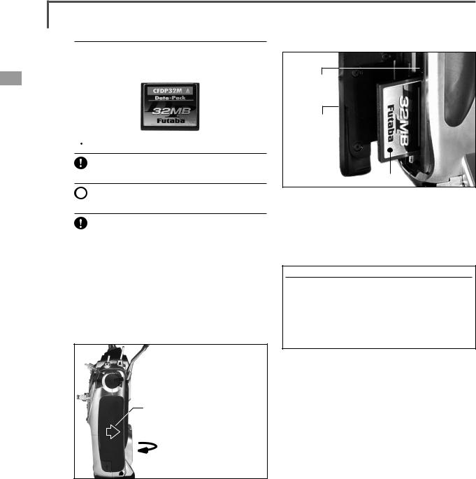
CF Card CFDP32M
CF (Compact Flash) card can store various files, such as model data, music, sound and pictures. Its memory size is 32MB.
 Warning
Be sure to turn off the power to the transmitter before inserting or removing the CF card.
 As the CF card is a precision device, do not use excessive force when inserting.
Be sure to use only Futaba's original CF card, CFDP32M, for the T14MZ transmitter.
* Futaba does not recommend any CF cards other than Futaba's original CF cards.
Set-up of CF card / Removal of CF card
1.Turn off the power to the transmitter.
2.Slide the card cover on the right side of the transmitter back, and pull open the cover towards you.
1. Slide backward the side cover of the transmitter.
2. Then, pull it toward you.
3.Inserting the card: Turn the CF card so that the name seal faces to the back of the transmitter. Then slide the card into the slot until the card touches bottom.
4.Press the card cover back and then slide it toward you to close it.
Removal of CF card:
1.Push the eject button and then take out the CF card.
2. Close the card cover and slide it to the original position.
●Eject
Button
●Side Cover
●CF Card
Read data from a PC
Saving music and image files edited by a PC into the CF card, you can use those files on your T14MZ transmitter. Equipment for reading and writing CF cards are available at most electronics stores.
[Important]
Before saving data from the PC, insert the CF card into the transmitter and turn on the power. To save a file from the PC, copy the file to a folder by file type, which are automatically written.
●BMP: Picture file ●WAV: Audio file ●WMA: Music file ●MODEL: Model data
*Use only CF card reader/writer that complies with CFA (CompactFlashTM Association) standard.
Stored data
The life of the CF card is limited due to the use of Flash memory. When you have a problem of saving or reading data such as picture data after a long period of use, please get a new CF card.
*We do not have the responsibility of compensating any failure or damage to the data stored in the memory card no matter what the reason is. Be sure to keep the backup of your important data in your CF card.
*No necessity for backup; T14MZ transmitters and CF cards are using nonvolatile memory devices so that the data stored in those will not be destroyed even without a backup battery. The clock for the transmitter depends on the Lithium battery.
18 <Before Use>

Connector/Plug
|
|
|
|
|
|
●Audio/ |
|
|
|
●DSC/Trainer |
|
|
|
|
|||
Battery Charge |
|
|
|||
Connector for trainer function (TRAINER)
When you use trainer function, connect the optional trainer cable between the transmitters for teacher and student.
*You can set the trainer function on the Trainer Function screen in the system menu.
Connector for DSC function (DSC)
You can operate the transmitter without transmitting radio waves by connecting the transmitter and the receiver to the DSC cable.
*Please refer to the section "Connection between Receiver/ Servo"
Audio plug (PHONE)
Connecting a stereo headphone to this plug, you can enjoy music files stored in the CF card.
Connector for battery charger (CHG)
This is the connector for charging the Lithium Ion battery LT2F2200 that is installed in the transmitter. Do not use any other chargers except CR-2500 that is for 12V application to charge the LT2F2200 battery through this connector.
 Danger
Do not connect any other chargers except CR-2500 to this charging connector.
*If you take out the Lithium Ion battery LT2F2200 from the transmitter, you can use the attached charger LBC-1D5 for charging the battery.
USB port (Transmitter right side)
*This is for factory use only.
<Before Use> 19

Installing and Removing of the battery LT2F2200 for the transmitter
Attachment of the battery
1.Hook one of your fingers in the slit formed by the transmitter’s main body and the battery cover on the bottom of the transmitter, and then pull up the cover to release the lock. You can now open the cover in the direction of the arrow.
2.Move the slide lever to the right end, and then install the battery in the holder.
Removing of the battery
Note: If you detach the battery while the power is on, the data you have set will not be saved.
1.Hook one of your fingers in the slit formed by the transmitter’s main body and the battery cover on the back and bottom of the transmitter, and then pull up the cover to release the lock. You can now open the cover in the direction of the arrow.
2.Slide the slide lever to the right while pressing it, the battery will be released.
●Move the slide lever to the far right.
3. Push the battery to the left with your finger.
4. Close and lock the battery cover until you hear a snapping sound.
 Warning
 Be careful to not drop the battery.
 Never take out the battery from the T14MZ transmitter while the LED monitor is blinking
yellow after turning off the power the T14MZ transmitter.
*Internal devices such as memories may have been destroyed.
*If there is any problem, the message "Backup Error" will be shown the next time when you turn on the power of the transmitter. Do not use the transmitter as it is, send it back for a check to the Futaba Service Center.
20 <Before Use>
RF module MZ-FM |
|
Toolbox |
 Caution
Be sure to turn off the power of the transmitter before you attach or detach the module.
●Connector
Detachment of the RF module
Pull the module straight while you are pushing inward the projections on both sides of the module.
*There is a connector above and under the module respectively. So, you might find difficulty in pulling out the module if the module is tilted.
Attachment of the RF module
Insert the module with care so that the connecter pins of the transmitter won't be bent.
●Tool for removing decoration nuts
●Rubber Cap
●Hex. Wrench (1.5mm and 2.5mm)
You can use the toolbox contained in the set for various adjustment of the transmitter.
Hexagonal wrench (1.5mm and 2.5mm)
These wrenches are for adjustment of sticks, replacement of the switches and adjustment of the antenna.
Tool for removing decoration nuts
This is for replacement of switches.
Stylus pen
Rubber cap is attached on the tip of the toolbox. You may use this tool as a stylus pen for operating touch panel. This stylus pen can let you do more precise operation than fingers without damaging the surface.
●You may use this tool as a stylus pen.
<Before Use> 21

Receiver nomenclature
Before using the receiver, be sure to read the precautions listed in the following pages.
Receiver R5014DPS
●Connectors
●Antenna
●B/C
●CH1 12
●DG1
●Monitor LED
●DG2
Connector
"1 through 12": outputs for the channels 1 through 12 "DG1", "DG2": outputs of DG1 and DG2 channels "B/C": connector for the power and DSC.
LED Monitor
This monitor is used to check the frequency of the receiver.
22 <Before Use>
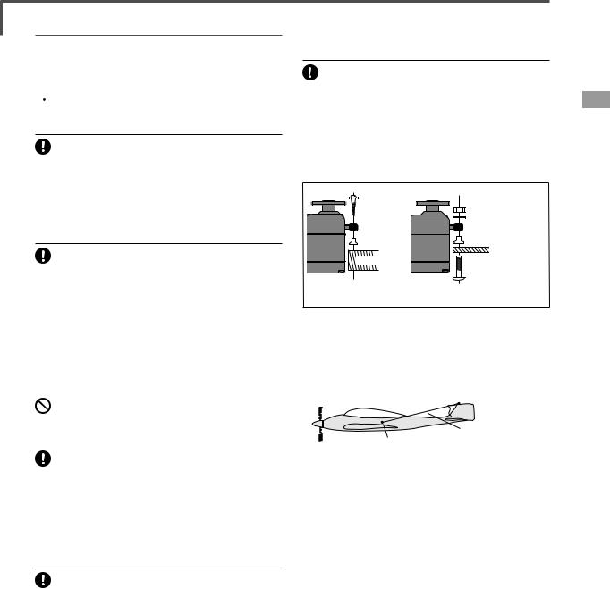
Safety precautions when you install receiver and servos
 Warning
Connecting connectors
Be sure to insert the connector until it stops at the deepest point.
*If a connecter comes out during the flight due to some reasons such as vibration, your aircraft will crash.
Mounting servos
Use a vibration-proof rubber (such as rubber grommet) under a servo when mounting the
servo on a servo mount. And be sure that the servo cases do not touch directly to the metal parts such as servo mount.
*If a servo case is in direct contact with the airframe, the vibration of the airframe directly travels to and may damage the servo.
How to protect the receiver from vibration and |
Wood screw |
2.3-2.6mm nut |
|
washer |
|
water |
Rubber |
Rubber |
grommet |
grommet |
Brass eyelet |
Brass eyelet |
Wrap the receiver with something soft such |
Servo mount |
Servo mount |
|
as foam rubber to avoid vibration. If there is |
2.3-2.6mm screw |
a chance of getting wet, put the receiver in a |
|
|
|
|
|
|
||
(Airplane/Glider) |
(Helicopter) |
|||||||
waterproof bag or balloon to avoid water. |
||||||||
|
|
|
|
|
|
|||
*Strong physical shock or water infiltration may damage |
|
|
|
|
|
|
||
the receiver and let the receiver malfunction to crash your |
|
|
|
|
|
|
||
aircraft. |
Internal antenna mounting (Airplanes) |
|||||||
Receiver's antenna |
|
|
|
|
|
|
||
●Use rubber band to stretch |
|
|
|
|
|
|||
|
|
|
|
|
|
|
||
|
|
antenna and then fix it. |
|
|
|
|
|
|
Never cut the receiver's antenna. Do not bind |
|
|
|
|
|
|||
|
|
|
|
|
|
|||
the receiver's antenna with the cables for |
|
|
|
|
|
|
||
servos. |
|
|
|
|
Antenna |
|
||
|
|
●Use a rubber bushing to the position where |
||||||
Locate the receiver's antenna as far as possible |
antenna is coming out from the airframe so |
|||||||
that the antenna won't |
be cut due to the |
|||||||
from metals such as frames. |
||||||||
friction. |
|
|
|
|
|
|||
|
|
|
|
|
|
|
||
*Cutting or binding the receiver's antenna will reduce the |
●Use rubber band to stretch antenna and then |
|||||||
radio reception sensitivity and the flight area, causing the |
fix it.Make a knot inside of the airframe so that |
|||||||
crash. |
the antenna will not fall out. |
|||||||
|
|
|
|
|
|
|
|
|
Servos throw
Adjust your system so that pushrods will not bind or sag when operating the servos to the
full extent.
*If excessive force is continuously applied to a servo, your aircraft may crash because the servo would be damaged and the battery would be consumed rapidly.
Mounting the power switch
When mounting a power switch to an airframe, make a rectangular hole that is a little larger than the total stroke of the switch so that you can turn ON/OFF without binding.
Avoid mounting the switch where it can be covered by engine oil and dust. In general, it is recommended to mount the power switch on the side of the fuselage that is opposite the muffler.
<Before Use> 23

BASIC OPERATION
Battery Charging
Before charging batteries, read the "Cautions for handling battery and battery charger" in the section "For your safety".
How to charge the Lithium Ion battery
LT2F2200 for the transmitter
 Danger
 The Lithium-Ion battery LT2F2200 is only for your T14MZ. Do not use this battery for other
equipment.
Be sure to use the battery charger LBC-1D5 to charge the battery.
To charge the battery while installed in the transmitter, use the optional battery charger
CR-2500 for 12V.
[Method of charging battery]
●Special Charger |
●Li-ion Battery |
LBC-1D5 |
LT2F2200 |
to AC Outlet
1.Connect the power cable to the charger.
2.Connect the power cable of the charger to the wall socket (AC outlet).
*The power lamp turns on.
3.Mount the battery and then slide the battery in the direction shown in the figure until you hear a locking sound.
*The charge-lamp turns on and charging starts.
4. When the charge-lamp turns off, charging has been completed.
*Be sure to remove the power cable from the wall socket after using a battery charger.
*It takes about two and a half hours for charging the battery pack that has been used fully. However, the charging time may vary depending on the surrounding air temperature and the condition of the battery pack.
*The charge LED blinks (error) if the battery is improperly mounted or the battery itself is a defective product. In this case, remount the battery or use another battery.
*If you mount a charged battery, the charge lamp will turn on for several seconds, but it will turn off later.
How to charge the Ni-Cd battery NR4F1500 for the receiver
Use the battery charger FBC-32A that is included in the set.
[Method of charging battery]
 AC Outlet
●Special Charger
FBC-32A
●Ni-Cd Battery
NR4F1500
1.Connect the power cable of the charger to the wall socket (AC outlet).
2.Connect the connector to the NiCd battery.
*Confirm that the charging indicator, LED lamp, is on.
3. Remove the battery after 15 hours.
*Battery charging will not automatically stop. Remove the battery from the charger and remove the charger from the wall socket.
*It is recommended to reactivate the battery by cycling several times if the battery has not been used for a long period.
*In case of NiCd battery, you may find the poor performance of the battery if you have used the battery only for a short period or if you repeat charging while the battery is not fully discharged. It is recommended to discharge the battery to the recommended level after your usage. It is also recommended to charge the battery just before your usage.
24 <Basic Operation>

How to turn ON/OFF the power of the transmitter
Windows® CE is installed as a built-in operating system in the T14MZ transmitter. Compared to the conventional system, the T14MZ takes extra time for internal processing when it is turned on/off. For safety reasons, the radio will be emmiting only after you push the confirmation button when turning on the power. Please follow the instructions for turning on/off the transmitter.
When turning on the power of the transmitter
1. Turn on the power switch of the transmitter.
*After initialization of the transmitter is over, the frequency confirmation screen pops up, and LED monitor turns on pink.
2.Check the frequency shown on the screen. If it is OK, then click the button "YES".
*LED monitor turns to green and the transmitter begins to emit radio waves.
*If you push the button "NO", then the transmitter will not emit radio waves.
Then, you will see the home screen and you will be able to set conditions.
Start-up time; The time required for initializing the internal circuit of the transmitter varies between the previous time you turned off the transmitter and the time you will turned on the power. There are two “start up” modes for your transmitter, see below:
Cold start;
If you turn on the transmitter more than four hours after you last turned it off, the mode is “Cold start”. “Cold start” is normal for the first initial power up of the day. It will take about 30 seconds to be ready for use, as it takes time to initialize the internal circuit of the transmitter.
Hot start;
If you turn on the transmitter less than four hours after you last turned it off, the mode is “Hot start”. Since initialization has been partly completed, the transmitter will be ready to use in several seconds. “Hot start” takes place usually at a second flight or later flight in the day.
 Warning
 Once you turn on the power, never shut off the power switch until the power becomes stable
(or until the first screen shows up). If you turn off the power switch while the transmitter is going through the initialization process, the data could be damaged. Note: The start-up time may be a little bit slower when the CF card is installed compared to when the card is not.
How to stop the transmitter
Turn off the power switch of the transmitter. The internal circuit of the transmitter starts the shut down process including saving the set-up data. The LED will blink yellow while the transmitter is in the shutdown process.
 Once you turn off the power, never operate the power switch until the power shutdown process
is fully completed. If you turn on the power switch again while the transmitter is still in the process of power shutdown, the data could be damaged.
As the internal circuit of the transmitter stays on the standby mode for 4 hours after turning off the power, some part of the circuit is consuming current. When you turn on the power during this period, the power starts in “Hot mode”. But if more than four hours pass after shutting down the power, the power supply will completely shut down the internal circuit. When you turn on the power after this point, the power starts in “Cold start mode”.
<Basic Operation> 25

●Reset Button
How to reset software
If the screen freezes for some reason and you cannot edit, the transmitter power supply is not shut off even if you turn OFF the power switch. You will need to use the reset button or remove the battery and reinsert it again. In this case, the power restarts in “Cold mode”. Even though the screen freezes, all the other functions for radio control operation remain operative.
How to change the frequency/How to set ID
The T14MZ system has employed the frequency synthesizer scheme. The T14MZ transmitter will set the frequency of the R5014DPS (PCMG3 receiver) by the wireless data transmission. When you are using a new PCMG3 receiver and changing the frequency, set ID or frequency by the following instructions.
In case of using PCMG3 receivers
*Make sure that PCM-G3 is set as a modulation scheme. Then change the frequency by the following instruction.
How to change the frequency
1.Turn on the power of the transmitter.
2.Push the area that shows the frequency in the home screen or push the "Frequency" button in the Linkage menu. Then the Frequency Set screen will pop up.
3.Push the "Receiver ID" button. Then ID inputting screen for receiver will pop up. Input the eight-digit ID code attached to the receiver's case. Push the "Yes" button after confirming the ID.
*Use the "BS" button to move back digit by digit for correction if you made a mistake. If you want to stop changing ID code halfway, push "Return" button to return to the previous screen.
*Once you set the ID code for a receiver, you don't have to set the ID code again as long as you change the receiver itself.
*When you need to use two receivers for a large size aircraft, you need to enter different ID codes to those receivers respectively.
4. Push the "Band NO. (Frequency)" button if you need to change the frequency. Then you will see frequencies on the screen. Select the frequency you want use. Push the button "Yes" after confirmation. Then you will see the "Confirmation of the change" box.
*If you have changed the module prior to turning on the power, confirmation screen will pop up to ask you whether you want to change the frequency. Push the button "Yes" to change the frequency.
5.If the frequency is correct, push the button "Yes". Then you will see the message "Transmitting the frequency data". It takes a certain time to send the new frequency data to the receiver with a sound. (If you need to resend the data, push the "Resend" button.)
6.Turn on the power of the receiver while the
26 <Basic Operation>

new frequency data is displayed. When the frequency setting for the receiver is completed, the LED monitor of the receiver blinks once and the 1CH servo shuttles three times across the neutral position.
*A very low power, whose frequency is different from that of the channel frequency, is used to set the frequency of the receiver. The reachable distance of the radio is designed to be within several feet. Therefore, put the transmitter and the receiver as close as possible when setting the frequency of the receiver.
*If the receiver can not load the new data due to environmental reasons, connect the transmitter and the receiver directly by the DSC cable. And do the procedure 6 and 7.
*LED monitor will blink on and off if the receiver's ID code is wrong. Then move back to the Receiver ID Set screen and restart the receiver's ID setting from the beginning.
7. Push the button "End" when the frequency setting is completed. Then turn off the power of the transmitter following the instructions shown on the screen. You will be able to use the new frequency after you turn on the power again.
In case of using PCM1024, PPM receivers
*Make sure that PCM1024 or PPM is set as a modulation scheme. Then change the frequency by the following instruction.
How to change the frequency
1.Turn on the power of the transmitter.
2.Push the area that shows the frequency in the home screen or push the "Frequency" button in the Linkage menu. Then the Frequency Set screen will pop up.
3.Push the "Band NO. (Frequency)" button if you need to change the frequency. Then you will see frequencies on the screen. Select the frequency you want use. Push the button "Yes" after confirmation. Then you will see the "Confirmation of the change" box.
*If you have changed the module prior to turning on the power, confirmation screen will pop up to ask you whether you want to change the frequency. Push the button "Yes" to change the frequency.
4. If the frequency is correct, push the button "Yes". Turn off the power of the transmitter following the instructions shown on the screen. You will be able to use the new frequency after you turn on the power again.
Registration of the user's name
T14MZ transmitter can register user's name.
How to register user's name
1.Turn on the power of the transmitter.
2.Push the area of the user's name shown on the home screen or the "user's name" in the linkage menu. Then the User's Name Set screen will pop up.
3.Push the user's name. Then the keyboard will pop up. You can use up to 32 characters as a user's name. Use the keyboard on the screen to enter user's name.
space key
4. Push "Return" key to return to the previous screen after entering the user's name.
(If you want to protect the user's name)
If you don't want anybody else to change your user's name, set your ID in the following way.
*Please be aware that you will not able to change user's name if you forget your password.
1.Make sure that the security mode is "User's name", and then push the User ID button.
2.Enter your password, using keyboard on the screen.
You will need to enter your password for changing the user's name from the next time you turn on the power of the transmitter.
*Even if you enter the same character, your password will be identified differently depending on whether you are using "Transform" mode or "Direct" mode for inputting.
<Basic Operation> 27
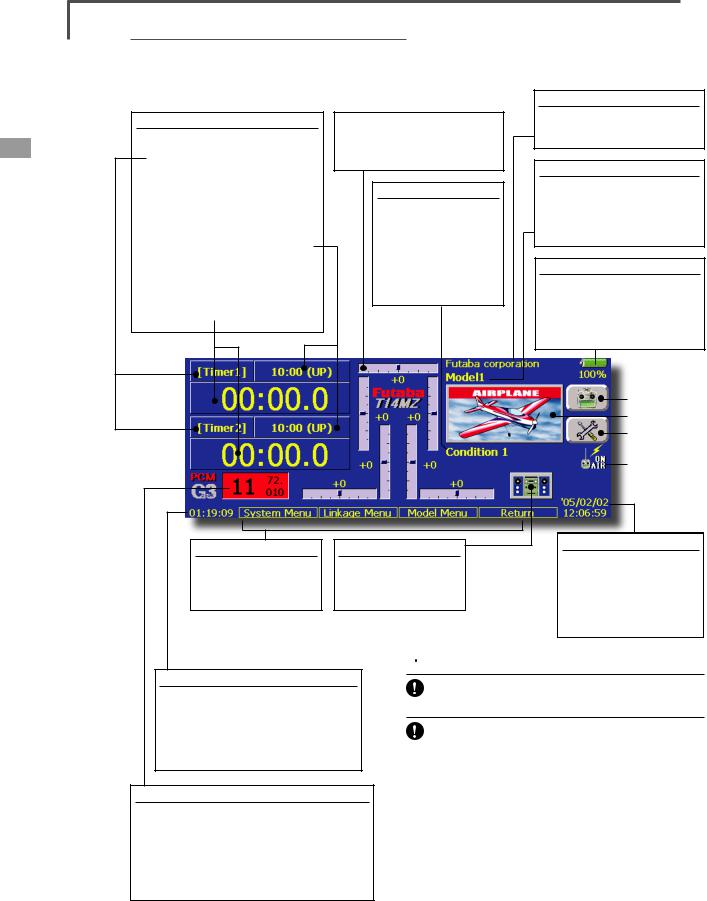
Home screen
Here is the home screen and its descriptions. Use your finger or included stylus pen to operate the touch screen.
Timer
• To call the setting screen
Push [Timer1] or [Timer2] to call the timer setting screen.
•To display and reset the setting
Time and mode (UP/DN) are displayed here. Push this area for resetting the timer.
•To display, start and stop the timer
Timer is displayed here. Push this area to start/stop the timer.
Digital trim (T1 to T6, CD)
Push this area to call the Dial Monitor screen.
Condition
The condition name that is currently used is displayed here.
•Push this area to call the Condition Select screen.
Direct buttons
Select and push one of the direct buttons to call its setting screen.
Music playback
•Push this button to call the Music Playback screen.
System timer/Reset
•This shows the accumulated time up to now since the latest reset.
(Hour):(Minute):(Second)
Push this area to reset the timer.
Modulation mode/Frequency
Modulation mode is displayed here. (PCM-G3/PC M1024/PPM)
•Band number and frequency are displayed here.
•Push the frequency displaying area to call the Frequency Set screen.
 Warning
Be sure to confirm the model name before flying your aircraft.
Check the remaining battery as often as possible and try to charge the battery earlier. If the battery
alarm makes a sound and its warning symbol is displayed, land your aircraft immediately.
Although you may notice the flickering of the numbers on the LCD screen, this is not an abnormal, because the LCD screen is frequently refreshing those even if those numbers are unchanged.
You can adjust the LCD contrast and the backlight brightness, and can change the duration time to turn off the backlight and color of the background by the screen setting in the system menu.
28 <Basic Operation>

Music playback
The T14MZ transmitter can play back the ".wma" music files stored in the CF (Compact Flash) card. You can listen to them through the built-in speaker or a headphone by the earphone plug.
*First, store music files from your PC into the WMA folder on the CF card, and then insert the CF card into your transmitter to play back music files on the transmitter.
[Important notice]
Before downloading files from your PC into the CF card, insert the CF card into the transmitter and turn on the power of the transmitter. Then the following folders will be automatically created in the CF card. When you download files from you PC, copy and paste the files into their corresponding files.
•BMP : picture files
•WMA : music files
•WAV : sound files
•MODEL : model data files
•Push the Music Playback button on the home screen to call the following set-up screen.
• Button to select either One-time Playback or Repeat Playback
• Return to the home screen
Buttons for music playback
•You can playback any music files listed on the right side of the screen.
•If you adjust the volume here, it adjusts not only music playback but also other applications.
• B u t t o n |
t o |
select either |
|
O n e M u s i c |
|
P l a y b a c k |
o r |
Multiple Music
Playback
• SW selection button
Push this button to call the SW select screen and choose the Music playback switch.
(Refer to the description in the end of this manual)
(Playback file list)
To playback
•All the music files saved in the CF card will be shown here.
1.Push the file name to select the music file you want to hear.
2.Use the buttons on the left to playback or stop the music.
<Basic Operation> 29

SYSTEM MENU
The System Menu sets up functions of the transmitter, this does not set up any model data.
●When the System Menu button is touched, the menu shown below is called. Call the setup screen by pressing the function you want to set up.
●Return to Home screen
System Menu functions table
[Trainer]: Starts and sets the trainer system.
[Display]: Display adjustment and auto power off setting.
[Date & Time]: Sets the date and time (system clock setting) and resets the timer. [User Name]: User name registration and ID Pin number.
[Switch]: Toggle switch type setting (Set when the switch is replaced.)
[H/W Reverse]: Reverses the direction of operation of the sticks, switches, trim levers, knobs, etc. [Information]: Displays the program version, CF card information, and product ID.
30 <Functions of System Menu>
 Loading...