


3PM-2.4G MX
3-channel, FASST Radio control system for Car
INSTRUCTION MANUAL
1M23N13518


 R Digital Proportional R/C System

Thank you for purchasing a Futaba 3PM-2.4G MX system.
Before using your 3PM-2.4G MX system, read this manual carefully in order to use your R/C set safely. After reading this manual, store it in a safe place.
Application, Export, and Modification
1.This product may be used for models only. It is not intended for use in any application other than the control of models for hobby and recreational purposes.
2.Exportation precautions:
(a)When this product is exported from the country of manufacture, its use is to be approved by the laws governing the country of destination for devices that emit radio frequencies. If this product is then re-exported to other countries, it may be subject to restrictions on such export. Prior approval of the appropriate goverment authorities may be required. If you have purchased this product from an exporter outside your country, and not the authorized Futaba distributor in your country, please contact the seller immediately to determine if such export regulations have been met.
(b)Use of this product with other than models may be restricted by Export and Trade Control Regulations, and an application for export approval must be submitted.
3.Modification, adjustment, and replacement of parts: Futaba is not responsible for unauthorized modification, adjustment, and replacement of parts on this product. Any such changes may void the warranty.
Compliance Information Statement (for U.S.A.)
This device, trade name Futaba Corporation of America, model number R603FF/FS, complies with part 15 of the FCC Rules. Operation is subject to the following two conditions:
(1)This device may not cause harmful interference, and
(2)This device must accept any interference received, including interference that may cause undesired operation.
The responsible party of this device compliance is: Futaba Service Center
3002 N Apollo Drive Suite 1, Champaign, IL 61822 U.S.A.
TEL (217)398-8970 or E-mail: support@futaba-rc.com (Support) TEL (217)398-0007 or E-mail: service@futaba-rc.com (Service)
Battery Recycling (for U.S.A.)
The RBRCTM SEAL on the (easily removable) nickel-cadmium battery contained in Futaba products indicates that Futaba Corporation of America is voluntarily participating in an industry program to collect and recycle these batteries at the end of their useful
lives, when taken out of service within the United States. The RBRCTM program provides
a convenient alternative to placing used nickel-cadmium batteries into the trash or municipal waste system, which is illegal in some areas.
You may contact your local recycling center for information on where to return the spent battery. Please call 1-800-8-BATTERY for information on Ni-Cd battery recycling in your area. Futaba Corporation of America's involvement in this program is part of its commitment to protecting our environment and conserving natural resources.
RBRCTM is a trademark of the Rechargeable Battery Recycling Corporation.
Warning: This product contains a chemical known to cause cancer and birth defects (or other reproductive harm).

FEDERAL COMMUNICATIONS COMMISSION
INTERFERENCE STATEMENT (for U.S.A.)
This equipment has been tested and found to comply with the limits for a Class B digital device, pursuant to Part 15 of the FCC Rules. These limits are designed to provide reasonable protection against harmful interference in a residential installation.
This equipment generates, uses and can radiate radio frequency energy and, if not installed and used in accordance with the instructions, may cause harmful interference to radio communications. However, there is no guarantee that interference will not occur in a particular installation. If this equipment does cause harmful interference to radio or television reception, which can be determined by turning the equipment off and on, the user is encouraged to try to correct the interference by one or more of the following measures:
--Reorient or relocate the receiving antenna.
--Increase the separation between the equipment and receiver.
--Connect the equipment into an outlet on a circuit different from that to which the receiver is connected.
--Consult the dealer or an experienced radio/TV technician for help.
CAUTION:
To assure continued FCC compliance:
Any changes or modifications not expressly approved by the grantee of this device could void the user's authority to operate the equipment.
Exposure to Radio Frequency Radiation
To comply with FCC RF exposure compliance requirements, a separation distance of at least 20cm must be maintained between the antenna of this device and all persons.
This device must not be co-located or operating in conjunction with any other antenna or transmitter.
•No part of this manual may be reproduced in any form without prior permission. •The contents of this manual are subject to change without prior notice.
•This manual has been carefully written. Please write to Futaba if you feel that any corrections or clarifications should be made.
•Futaba is not responsible for the use of this product.

Table Of Contents |
|
For Your Safety As Well As That Of Others |
...........6 |
Explanation of Symbols ................................................................................ |
6 |
R603FF/603FS Precautions .......................................................................... |
6 |
Operation Precautions .................................................................................. |
7 |
NiCd Battery Handling Precautions ............................................................. |
9 |
Storage and Disposal Precautions ............................................................ |
10 |
Other Precautions ....................................................................................... |
11 |
Before Using ........................................................... |
12 |
Features........................................................................................................ |
12 |
Set Contents ................................................................................................ |
14 |
Nomenclature (Transmitter/Receiver/Servo) ............................................ |
15 |
Installation .............................................................. |
22 |
Receiver and Servo Connections .............................................................. |
22 |
Installation Safety Precautions .................................................................. |
22 |
Initial Set-Up ........................................................... |
24 |
How to link the transmitter and the receiver............................................. |
24 |
How to set the F/S position (PPM mode)................................................... |
24 |
Preparations (Transmitter) ......................................................................... |
25 |
Function Map .......................................................... |
28 |
(Function Selection) .................................................................................... |
28 |
Functions ................................................................ |
30 |
End Point Adjuster ...................................................................................... |
30 |
Steering Speed ............................................................................................ |
33 |
Steering EXP / Throttle EXP ....................................................................... |
34 |
A.B.S. Function ............................................................................................ |
36 |
Throttle Acceleration................................................................................... |
38 |
Brake Mixing ................................................................................................ |
40 |
Programmable Mixing ................................................................................. |
41 |
4WS Mixing .................................................................................................. |
42 |
Fail Safe/Battery Fail Safe (HRS mode) ..................................................... |
44 |
Trim ............................................................................................................... |
45 |
Steering D/R ................................................................................................. |
46 |
ATL Function ............................................................................................... |
46 |
Channel 3 Position ...................................................................................... |
47 |
4

Subtrim ............................................................................................... |
48 |
Channel Reverse ............................................................................... |
49 |
Model Select ...................................................................................... |
50 |
Timer................................................................................................... |
51 |
(System Functions) |
|
Model Copy ........................................................................................ |
53 |
Model Reset ....................................................................................... |
54 |
Model Name ....................................................................................... |
54 |
HRS/PPM Select ................................................................................ |
55 |
Function Select Switch ..................................................................... |
56 |
Function Select Lever ....................................................................... |
57 |
Digital Trim Step ................................................................................ |
58 |
Condition 2 Selection........................................................................ |
59 |
LED Mode Selection .......................................................................... |
59 |
Adjuster .............................................................................................. |
60 |
Reference ......................................................... |
61 |
Ratings ............................................................................................... |
61 |
Optional Parts .................................................................................... |
62 |
Troubleshooting ................................................................................ |
63 |
Error Displays .................................................................................... |
64 |
When requesting repair .................................................................... |
65 |
For Your Safety
As Well As
That Of Others
Before
Using
Installation
Initial
Set-Up
Function
Map
Functions
Reference
5

Your For
As Safety
As Well
Of That
Others
For Your Safety As Well As That Of Others
Use this product in a safe manner. Please observe the following safety precautions at all times.
Explanation of Symbols
The parts of this manual indicated by the following symbols are extremely important and must be observed.
Symbols |
Explanation |
Indicates a procedure which could lead to a dangerous situ-
Danger ation and may cause death or serious injury if ignored and not performed properly.
Indicates procedures which may lead to dangerous situa- Warning tions and could cause death or serious injury as well as su-
perficial injury and physical damage.
Caution |
Indicates procedures that may not cause serious injury, but |
could lead to physical damage. |
Symbols:  ; Prohibited
  ; Mandatory
R603FF/FS Precautions
 Caution
Mandatory Procedures
Always use R603FF/FS under the following conditions;
Power supply: 6V Nicd battery (PPM/HRS mode)
Servo: 6V type Futaba Digital Servo (HRS mode)
If these conditions are not followed, control may be impossible or the servo may be damaged.
6

Operation Precautions
 Warning
Prohibited Procedures
Do not operate outdoors on rainy days , run through puddles of water, or use when visibility is limited.
Should any type of moisture (water or snow) enter any component of the system, erratic operation and loss of control may occur.
Do not operate this R/C system when you are tired, not feeling well or under the influence of alcohol or drugs.
Your judgment is impaired and could result in a dangerous situation that may cause serious injury to yourself as well as others.
Do not operate in the following places.
-Near people or roads.
-On any pond when boats are present.
-Near high tension power lines or communication broadcasting antennas.
Interference could cause loss of control. Improper installation of your Radio Control System in your model could result in serious injury.
Mandatory Procedures
 Adjust the antenna vertically to the ground.
Otherwise, the operating range may become shorter.
 Always perform an operating range check prior to use.
Problems with the radio control system as well as improper installation in a model could cause loss of control.
Simple range test method;
Have a friend hold the model, or clamp it down or place it where the wheels or prop cannot come in contact with any object. Walk away and check to see if the servos follow the movement of the controls on the transmitter. Should you notice any abnormal operation, do not operate the model. Also check to be sure the model memory matches the model in use.
 Caution
Prohibited Procedures
Never hold only the an- |
Do not touch the engine, motor, speed control or |
|
tenna. |
|
any part of the model that will generate heat while |
Hold the grip handle, otherwise the |
the model is operating or immediately after its use. |
|
antenna may be damaged. |
|
|
These parts may be very hot and can cause serious burns. |
||
Mandatory Procedures
When making adjustments to the model, do so with the engine not running or the motor disconnected.
You may unexpectedly lose control and create a dangerous situation.
For Your Safety As Well As That Of Others
7

Your For
As Safety
As Well
Of That
Others
(Turning on the power switches)
 Always check the throttle trigger on the transmitter to be sure it is at the neutral position.
1.Turn on the transmitter power switch.
2.Turn on the receiver or speed control power switch.
(Turning off the power switches)
 Always be sure the engine is not running or the motor is stopped.
1.Turn off the receiver or speed control power switch.
2.Then turn off the transmitter power switch.
If the power switches are turned off in the opposite order the model may unexpectedly run out of control and cause a very dangerous situation.
(Fail safe function) ---when using HRS mode
Before running (cruising), check the fail safe function.
Check Method:
Before starting the engine, check the fail safe function as follows:
1.Turn on the transmitter and receiver power switches.
2.Wait at least one minute, then turn off the transmitter power switch. (The transmitter automatically transfers the fail safe data to the receiver every minute.)
3.Check if the fail safe function moves the servos to the preset position when reception fails.
The fail safe function is a safety feature that minimizes set damage by moving the servos to a preset position when reception fails. However, if set to a dangerous position, it has the opposite effect.
Setting example: Throttle idle or brake position
(Fail safe function) ---when using PPM mode
Always set the F/S position after turning on the transmitter power.
F/S Position Setting Method:
Move and hold the throttle trigger to the F/S servo position where you want to set (Throttle idle or brake position).
Then push the F/S switch on the transmitter. The LED blinks green.
8

NiCd Battery Handling Precautions
(Only when NiCd batteries are used)
 Warning
Mandatory Procedures
Always check to be sure your batteries have been charged prior to operating the model.
Should the battery go dead while the model is operating, loss of control will occur and create a very dangerous situation.
When the model is not being used, always remove or disconnect the NiCd battery.
Leaving the battery connected could create a dangerous situation if someone accidentally turns on the receiver power switch. Loss of control would occur.
When the system will not be used for any length of time store the system with batteries in a discharged state. Be sure to recharge the batteries prior to the next time the system is used.
If the batteries are repeatedly recharged in a slightly discharged state the memory effect of the NiCd battery may considerably reduce the capacity. A reduction in operating time will occur even when the batteries are charged for the recommended time.
To recharge the transmitter and/or receiver NiCd batteries, use the special charger made for this purpose.
Overcharging could cause the NiCd battery to overheat, leak or explode. This may lead to fire, burns, loss of sight and many other types of injuries.
Special
 Charger
Prohibited Items
Do not throw NiCd batteries into a fire. Do not expose NiCd batteries to extreme heat. Also do not disassemble or modify a NiCd battery pack.
Overheating and breakage will cause the electrolyte to leak from the cells and cause skin burns, loss of sight as well as other injuries.
For Your Safety As Well As That Of Others
Caution
Prohibited Items
Do not use commercial AA size NiCd batteries. 
Quick charging may cause the battery contacts to overheat and damage the battery holder.
Do not drop the NiCd battery or expose it to strong shocks or vibrations.
The battery may short circuit and overheat. Electrolyte may leak out and cause burns or chemical damage.
Do not short circuit the NiCd battery |
Shock |
terminals. |
Prohibited |
|
Causing a short circuit across the battery terminals may result in abnormal heating, fire and burns.
<NiCd Battery Electrolyte>
The electrolyte in NiCd batteries is a strong alkali. Should you get even the smallest amount of the electrolyte in your eyes, DO NOT RUB. Wash immediately with water and seek medical attention at once. The electrolyte can cause blindness. If electrolyte comes in contact with your skin or clothes,
wash with water immediately.
9
Your For
As Safety
As Well
Of That
Others
Storage and Disposal Precautions
 Warning
Prohibited Procedures
 Do not leave the radio system or models within the reach of small children.
A small child may accidentally operate the system. This could cause a dangerous situation and injuries. NiCd batteries can be very dangerous when mishandled and cause chemical damage.
 Caution
Prohibited Procedures
Do not store your R/C system in the following places.
-Where it is extremely hot or cold.
-Where the system will be exposed to direct sunlight.
-Where the humidity is high.
-Where vibration is prevalent.
-Where dust is prevalent.
-Where the system would be exposed to steam and condensation.
Storing your R/C system under adverse conditions could cause deformation and numerous problems with operations.
Mandatory Procedure
If the system will not be used for a long period of time, remove the batteries from the transmitter and model and store in a cool, dry place.
If the batteries are left in the transmitter, electrolyte may leak and damage the transmitter. This applies to the model also. Remove the batteries from it also to prevent damage.
<NiCd Battery Recycling>
A used NiCd battery is valuable resource. Insulate the battery terminals and dispose of the battery by taking it to a battery recycling center.
10
Other Precautions
 Caution
Prohibited Procedures
Do not expose plastic parts to fuel, motor spray, waste oil or exhaust.
The fuel, motor spray, waste oil and exhaust will penetrate and damage the plastic.
Mandatory Procedures
Always use only genuine Futaba transmitters, receivers, servos, FET a m p s ( e l e c t r o n i c s p e e d controls),NiCd batteries and other optional accessories.
Futaba will not be responsible for problems caused by the use of other than genuine Futaba parts. Use the parts specified in the instruction manual and catalog.
For Your Safety As Well As That Of Others
11

Using Before
12
Before Using
Features
This system is based on the combination of the newly developed 2.4GHz transmitter and its corresponding receiver. The system utilizes the 2.4GHz-SS radio communication and an ultra small antenna. In addition, the system inherits Futaba's unique HRS (High Response System).
-2.4GHzSS (Spread Spectrum) radio communication system
-Frequency channel setting unnecessary
Sifting the channels within the 2.4GHz band automatically, this system minimizes the interference from other 2.4GHz systems.
-Accepts no unwanted signals by using ID code
-The function "Auto-Detect" is utilized to automatically determine which mode is active, HRS or PPM mode. (R603FF/FS)
-Diversity antenna (R603FS)
-Simple segment type LCD display and four edit keys for easy data setup
-10 model memory
Model names can use up to 3 letters, numbers, and symbols so that easily understood names can be set. Model copy function simplifies creation of a model memory with different fine setups.
- Two function groups: Frequently used functions / System functions
Frequently used functions can be easily called from the initial screen with Select Key (SEL).
- 4WS mixing (4WS)
This mixing is used with Crawler and other 4WS specification cars. The 1st channel controls the front side steering and the 3rd channel controls the rear side steering. The operation mode of the front and rear wheels can be switched by switch (SW1).
- Brake mixing for large cars (BMX)
Brake mixing of the front and rear wheels of 1/5GP cars, etc. has balance adjustment functions.
- Steering dual rate (D/R-ST)
Steering angle can be adjusted with digital trim lever.
- Anti-skid Braking System (ABS)
This function applies the brakes so that the tires of gasoline engine cars, etc. do not lose their grip on the road even when braking at corners.
- Throttle acceleration (ACC)
Gasoline engine cars have a time lag before the clutch and brakes are connected. The ACC function minimizes this time lag.
- Steering speed (SPD)
When you sense that the steering servo is too fast, etc., the servo operating speed (direction that suppresses the maximum speed) can be adjusted.

- Racing timer (TIMER) : Up timer or Down timer can be selected.
A lap time can record 100 lap times and the total time. The timer can also be started automatically by trigger operation. The race time can be set.
- Digital trim: Steering trim, Throttle trim, Steering D/R, Throttle ATL
The current position is displayed on the LCD screen for about three seconds when each digital trim is operated.
- Function select lever function (FNC-DT1/DT2/DT3/DT4)
This function assigns a function to levers (digital trims, grip levers). Trim positioning at each model call is unnecessary because all the levers are digital.
- Digital trim step function (STP-DT1/DT2/DT3/DT4)
The digital trim (DT1/DT2/DT3/DT4) step amount can be adjusted by means of this function.
- Function select switch function (FNC-SW1/SW2)
This function assigns a function to the two installed switches.
- Condition 2 Selection
In specific functions, two rates can be set up, and switched with SW1 switch simultaneously during a run.
-NEW design considers operability and weight balance
-Adjuster function (ADJ)
Steering wheel and throttle trigger neutral position and operating angle correction can be applied.
- Tension adjustment function
The wheel tension can be adjusted from the outside.
-Trigger stopper function (Mechanical ATL)
-High luminosity blue LED pilot lamp
You can select your desired brightness of the pilot lamp. (Four steps)
Before Using
13

Set Contents
Your 3PM-2.4G MX system includes the following:
Using Before
|
3PM-2.4G MX system |
|
|
Transmitter |
T3PM-2.4G MX |
|
|
Receiver |
R603FF or R603FS |
|
|
|
Transmitter battery holder |
Miscellaneous |
Receiver switch |
|
Instruction manual |
|
|
 Caution
Always use R603FF/FS under the following conditions:
Power supply: 6V NiCd battery (PPM/HRS mode)
Servo: 6V type Futaba Digital Servo (HRS mode)
If the conditions are different, control is impossible or the servo may be damaged.
 Caution
Always use only genuine Futaba transmitter, receiver, FET amp, NiCd battery and other optional parts.
Futaba will not be responsible for damage caused by other than genuine Futaba parts and components. Use only the genuine Futaba parts and components listed in the instruction manual and catalog.
14
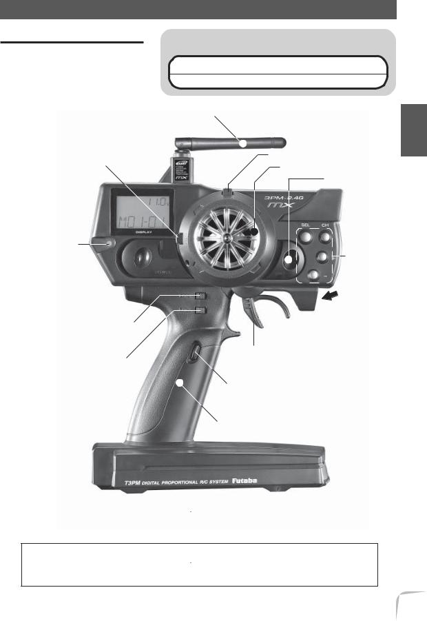
Transmitter T3PM-2.4G MX
Nomenclature
 Caution
 Never hold the antenna alone.
Hold the grip handle. Otherwise the antenna may be damaged.
Antenna
(See page 16 for the operating instructions.)
Throttle trim (DT2)
LCD screen 

Pilot lamp Power switch 

(See page 16 for the operating instructions.)
Steering dual rate lever (DT3)
ATL lever (DT4)
(See page 16 for the operating instructions.)
(See page 16 for the operating instructions.)
Steering trim (DT1) Steering wheel
CH3 switch ( SW2)
Edit keys
Mechanical ATL adjusting screw
(See page 17 for the
Throttle adjustment instructions.)
trigger
Push switch (SW1)
Grip Handle
*The switches and levers in the figure are shown in the initial setting position.
Precautions when turning the power switch on and off.
When the data is changed using the edit keys or trim levers, wait at least two seconds before turning off the power. If the power is turned off within two seconds after the data was changed, the new data will not be written to memory.
Before Using
15

Adjustment of the antenna direction
 Warning
 Adjust the antenna vertically to the ground.
Otherwise, the operating range may become shorter.
(Antenna Moving Range)
Antenna
Using Before
Digital Trim Operation
(Initial settings: DT1: Steering trim, DT2: Throttle trim)
Push the lever to the left or right (up or down).
The current position is displayed on the LCD screen for about three seconds when each digital trim is operated.
DT1
DT2
Steering trim |
Throttle trim |
position |
position |
-Each step is indicated by a tone.
-When the trim exceeds the maximum trim adjustment range, the tone will change pitch and the lever will not move any farther.
Trim Operation
With the digital trim feature, trim adjustments have no effect on the maximum servo travel. This prevents the linkages from binding when adjustments are made.
- The digital trim (DT1/DT2/DT3/DT4) step amount can be adjusted by the Digital trim step function (STP-DT), see page 58.
Grip lever operation
(Initial settings: DT3=Steering D/R, DT4=Throttle ATL)
Push the lever to the left or right. The current set value is displayed on the LCD screen for about three seconds when each lever is operated.
- The digital trim (DT1/DT2/DT3/DT4) step amount can be adjusted by the Digital trim step function (STP-DT), see page 58.
16

Steering D/R rate |
ATL position |
DT3 |
- A click sound is made at each step. |
|
- When the maximum position is reached at each side, |
||
DT4 |
||
the tone of the click changes. Thereafter, the set value |
||
|
||
|
does not change. |
Mechanical ATL Adjustment
Make this adjustment when you want to make the throttle trigger brake (reverse) side stroke narrower.
Adjustment
Using a Phillips screwdriver, adjust the trigger brake (reverse) side stroke by turning the screw through the adjusting hole indicated by the arrow in the figure. (The screw moves the throttle trigger stopper.)
- When the adjusting screw is turned clockwise, the stroke becomes narrower.
Mechanical ATL
adjustingscrew
Caution
When the stroke is adjusted, the throttle servo travel must be adjusted by data setting.
Wheel Tension Adjustment
Make this adjustment when you want to change the steering wheel spring tension.
Adjustment
Turn the screw inside the adjusting hole using a Phillips screwdriver.
- Turning the adjusting screw clockwise increases the spring tension.
Caution
If turned too far counterclockwise, the adjusting
screw may fall out.
Tension adjusting screw
Before Using
17

Using Before
Battery Replacement
For dry cell battery system
Load the eight batteries in accordance with the polarity markings on the battery holder. (8 AA Size Batteries)
(Battery Replacement Method)
1.Remove the battery cover from the transmitter by sliding it in the direction of the arrow in the figure.
2.Remove the used batteries.
3.Load the new AA size batteries . Pay very close attention to the polarity markings and reinsert accordingly.
4.Slide the battery cover back onto the case.
 Caution
Always be sure you reinsert the batteries in the correct polarity order.
If the batteries are loaded incorrectly, the transmitter may be damaged.
When the transmitter will not be used for any period of time, always
remove the batteries.
If the batteries do happen to leak, clean the battery case and contacts thoroughly. Make sure the contacts are free of corrosion.
Check:
Turn the power switch on the transmitter to the ON position. Check the battery voltage display on the LCD screen.
If the voltage is low, check the batteries for insufficient contact in the case or incorrect battery polarity.
Low Battery Alarm:
If the transmitter battery voltage drops below 8.5V an alarm will sound and "LOW BT" will be displayed on the LCD screen.
The low battery alarm is meant to be a safety feature only. Do NOT operate your radio below 9V. Always shut your radio off as soon as possible after the low battery warning tone to avoid loss of control.
18

For NiCd battery system
The NiCd battery is connected by a connector so it can be easily removed when the transmitter is not being used for an extended amount of time.
- Always use an NT8F1100B NiCd battery.
NiCd battery |
Charging jack |
|
NT8F1100B |
||
|
Charging the NiCd Battery
Charging
1.Plug the transmitter cord of the special charger into the charging jack on the side of the transmitter.
2.Plug the charger into an AC outlet.
3.Check that the charging LED lights.
 AC outlet
Charger
Transmitter charging
LED
Cord to transmitter charging jack
Before Using
When charging the NT8F1100B NiCd battery with the special charger FBC-19B(4) (for U.S.A.), allow about 24 hours for charging. If the transmitter has not been used for some time, cycle the battery by charging and discharging it two or three times.
Over current protection
The transmitter charging circuit is equipped with an over current protection circuit. If the battery is charged with a quick charger for other than digital proportional R/C sets, it may not be fully charged.
19

Using Before
 Warning
Never plug it into an outlet of other |
|
Do not insert and remove the |
than indicated voltage. |
|
charger when your hands are wet. |
|
|
|
Plugging the charger into the wrong outlet may re- |
|
|
|
It may cause an electric shock. |
sult in an explosion, sparking, or fire.
Always use the special charger or a quick charger for digital pro- |
|
portional R/C sets to charge a digital proportional R/C set NiCd |
|
battery. |
Use the |
Overcharging a NiCd battery can result in burns, fire, injuries, or loss of sight due to |
special |
overheating, breakage, or electrolyte leakage. |
charger. |
 Caution
Never try to recharge a dry cell bat- |
|
When the charger is not in use, dis- |
tery. |
|
connect it from the AC outlet. |
|
|
|
The transmitter may be damaged or the battery |
|
Do this to prevent accidents and to avoid overheat- |
electrolyte may leak or the battery may break. |
|
ing. |
Set data backup
The set data of each function of the T3PM-2.4G MX transmitter is stored in a memory element that does not require a backup battery. Therefore, the transmitter can be used without paying attention to the backup battery life.
20
 Loading...