


 Loading...
GOVERNOR FOR MODEL HELICOPTER
GV-1
INSTRUCTION MANUAL
3

Thank you for purchasing a Futaba GV-1 governor.
To ensure safe use, please read this manual thoroughly before using your new governor. After reading this manual, store it in a safe place.
FOREWORD
The GV-1 is an engine governor for model helicopters.
The governor automatically maintains constant rotor R.P.M.due to load changes (reaction to torque) by suppressing variations in the engine speed. The GV-1 works very well in all maneuvers, from hovering to flying.
-Engine speed can be set from both the GV-1 and the transmitter. -A magnetic sensing system reads the engine speed.
-Fuel mixture control can be set.
-An LCD panel displays the engine speed and set data.
-No part of this manual may be reproduced in any form without prior permission.
-The contents of this manual are subject to change without prior notice.
-This manual has been carefully written. Please contact Futaba if you feel that any corrections or clarifications should be made to the contents of this manual.
-Futaba is not responsible for the results of use of this product by the customer.
4

 TABLE OF CONTENTS
PRECAUTIONS 6
Definition of symbols 6
Setting precautions 7
Operating precautions 9
BEFORE USE 10
Set contents 10
Nomenclature 11
Overview of GV-1 operation 12
Examples 14
ASSEMBLY & ADJUSTMENT 16
Mounting the magnet and sensor 16 GV-1 connections 21
Fuselage setting precautions 22
FUNCTIONS 24
LCD display and edit keys 24
Low battery alarm 24
Function map 25
Initial setting for governor operation 26
Description of functions 33
REFERENCE 47
Specifications 47
Glossary 48
GV-1 PARAMETERS SHEET 49
REPAIR SERVICE 50
5

PRECAUTIONS
PRECAUTIONS
To ensure safe use, please observe the following precautions.
Definition of symbols
Pay close attention to the parts of this manual indicated by the following symbols.
Symbol |
Meaning |
Indicates a procedure that could result in serious injury or death to the user or other persons if ignored and not performed properly.
Indicates a procedure that could result in death or serious injury to the user or other persons, as well as physical damage, if ignored and not performed properly.
Indicates a procedure that may result in serious injury to the user or other persons, or physical damage only, if ignored and not performed properly.
Graphic symbols
 ; Operations that must not be performed.
; Operations that always must be performed.
6

Setting precautions
When using the GV-1 for the first time, or when making changes in the throw of a servo, always perform the limit setting operation.
(Setting method: Page 45)
Always set battery fail safe function at the GV-1. (Setting method: Page 44)
Since the GV-1, when used, controls the throttle, the battery fail safe function that is in a PCM transmitter will not be used.
Because the GV-1 controls the throttle, the throttle channel fail safe function normally set in a PCM transmitter will not be used. Set the fail safe function as described below.
Transmitter setting
Use the fail safe function for the channel that turns the governor on and off to set the fail safe position to the point at which the governor is turned off. With this setting, when the system enters the fail safe state, the governor will be turned off and the receiver throttle signal will be output directly.
PRECAUTIONS
7

PRECAUTIONS
The center of the sensor is different from the center of the sensor case so be careful when mounting the sensor.
(Setting method: Page 16)
Center of sensor is offset.
Sensor case
2.2 |
|
mm |
|
3.7mm |
3.7mm |
When using the PCM1024Z transmitter
When using the condition hold (CHD) function, always set the throttle servo maximum operating point (MAX THR) to 20% or less.
Depending on the conditions, this setting will turn on the governor and prevent the engine from exceeding the set speed even when condition hold is set.
(Governor ON conditions)
The following conditions must be performed, to turn on the governor:
-Governor ON/OFF switch set to ON position. -Throttle stick set to 20% or more from slow position. -Engine speed raised to 70% or more of set speed.
8

Operating precautions
At the beginning of flight, keep the governor in the OFF state by setting the throttle stick to no more than 20% from the slow side.
While the engine is running, turn on the governor at the point which the throttle stick is at least 20% from the slow side and the engine speed exceeds 70% of the set speed.
When the model is on the ground, lower the pitch to the position at which the model does not try to lift off. Do not take your eyes off the model.
When the governor operates and the rotor speed increases the lift also increases causing the model to try lift off , depending on the pitch position.
Periodically check the sensor output. (Check method: Page 46)
The magnet rotates at high speed and is subjected to a large centrifugal force.
Check the sensor output and mounting state about once every 10 flights.
If the model begins to shake during operation, immediately turn off the governor.
(See "Governor on/off operation mode setting" on page 29.)
When engine speed is not stable at high R.P.M.'s
The carburetor design, etc. may cause the engine to operate unstable. If this occurs, lower the maximum speed setting to the range over which there is no problem.
PRECAUTIONS
9

BEFORE USE
Set contents
Immediately upon opening the carton, check if the following items are supplied.
GV-1 control amp
USE BEFORE
Seal
|
SENSOR |
SENS. |
THRO |
MXTR |
|
|
& Sx |
|
|||
|
|
|
|
|
|
|
Tx |
r.p.m 1 |
r.p.m 2 |
r.p.m 3 |
|
|
m.trim |
GOV on |
GOV off |
|
|
|
GV-1 |
on / off |
r.p.m |
THRO |
|
|
m.trim |
|
|
|
|
|
|
|
|
|
|
|
|
|
|
|
|
|
|
|
|
|
|
Magnet
GV-1 magnetic sensor
Sensor mounting stay
For 30 engine
For 60 engine
Sensor mounting screws
Miniature screwdriver
10

Nomenclature
Control amp
LCD display panel
Displays the speed and set data.
Sensor connector

 Servo connectors

 Receiver connectors Edit keys
Used to set data. Press with the accessory miniature screwdriver.
LCD contrast trimmer
The display contrast can be adjusted so that the LCD display is easy to read. Adjust the contrast with the accessory miniature screwdriver.
BEFORE USE
Seal
Stick this seal to the sensor and servo connectors, transmitter switch, etc.
|
SENSOR |
SENS. |
THRO |
MXTR |
|
|
& Sx |
|
|||
|
|
|
|
|
|
|
Tx |
r.p.m 1 |
r.p.m 2 |
r.p.m 3 |
|
|
m.trim |
GOV on |
GOV off |
|
|
|
GV-1 |
on / off |
r.p.m |
THRO |
|
|
m.trim |
|
|
|
|
|
|
|
|
|
|
|
|
|
|
|
|
|
|
|
|
|
|
11

USE BEFORE
12
Overview of GV-1 operation
The GV-1 operates from 1000 to 2100rpm main rotor speed . However, the engine must be running at the set speed. The GV-1 turns off the governor when the engine is starting or idling.
*Governor operation = Operation that stabilizes the engine speed at the set speed.
When governor turned on and off by switch (Normal condition)
Setting the switch to the ON position turns on the governor. The following describes this operation.
Governor can be turned on and off by a switch.
-Throttle stick set at least 20% from slow position and engine running at 70% or more of set speed ->->-> ON
-Throttle stick set to maximum slow position ->- >-> Remains ON
-Switch set to off position ->->-> OFF
When governor turned on and off by transmitter throttle stick
The data is set so that the governor can be turned on and off with the transmitter throttle stick. The following describes this operation.
100%
 15% or less (OFF region)
0%
(OFF at slow side)
-Throttle stick set at least 20% from slow side and engine running at 70% or more of set speed ->->-> ON
-Throttle stick held at 15% or more from slow side ->->-> Remains ON
-Throttle stick lowered 15% or more from slow side ->->-> OFF
(Governor operating point)
Set speed
20% or more of stick deflection and 70% of set speed
 For safe operation, do not turn on the governor under the conditions shown below. If satisfied while the governor is on, the following conditions will forcibly turn the governor off.
When the governor is off, the transmitter throttle stick controls the throttle servo.
-Engine started while governor switch in ON position.
-Engine speed is 70% or less of set speed and throttle stick is set to 20% or less from slow side after engine started (governor starting only).
-Speed set to 999rpm or less (OFF setting). -Stick signal is lower than stop position setting. -Engine stopped, or sensor signal abnormal.
-Throttle stick set 15% or less from slow side (only when function that turns governor on and off by stick is set).
 The following operations do not indicate trouble: (When engine speed rises above the set speed)
A near-vertical dive may cause the engine speed to rise above the set speed.
(Throttle operation speed and ON/OFF point)
If throttle operation exceeds 70% of the set speed and the rotor speed rises to the set value, the ON/OFF point may seem to differ with the operating speed. Delay operation to smoothen the switching operation causes this and does not mean that the ON/OFF point has changed.
(Deviation from set speed)
The GV-1 stabilizes the engine speed to within +1% of the set speed. For example, if the rotor R.P.M. is set to1500rpm, the Rotor R.P.M. speed will deviate about +15rpm. However, this poses no problem from the standpoint of practical use.
BEFORE USE
13

Examples
The GV-1 functions can be selected to match the transmitter used. Select the functions by referring to the examples shown below.
USE BEFORE
Example 2 Example 1
Example 3
|
Function |
|
|
Connection |
|
Speed |
Governor |
Mixture |
|
||
|
|
||||
switching |
on/off |
function |
|
|
|
1 |
|
|
Sx |
Throttle servo |
|
OFF |
None |
Not connected |
|||
2 |
ON |
|
|||
3 |
|
|
|
||
|
|
|
|
||
Three |
ON/OFF |
|
Rx |
2P switch channel |
|
positions |
|
|
|||
CH7(example) |
CH8(example) |
|
|
3P switch channel |
|
When used with PCM1024Z |
|
Throttle channel |
|||
|
|
||||
1 |
Speed |
|
Sx |
Throttle servo |
|
switching |
None |
Not connected |
|||
OFF |
|||||
position 1 |
|
||||
3 |
|
|
|
||
used |
|
|
|
||
Two positions |
|
|
|
||
|
|
Rx |
Not connected |
||
CH7(example) |
|
|
|||
When used with FF8 or PCM1024Z |
|
3P switch channel |
|||
|
|
||||
(without mixture function) |
|
Throttle channel |
|||
|
Speed |
|
Sx |
Throttle servo |
|
OFF |
switching |
|
|||
|
Mixture servo |
||||
2 |
position 1 |
|
|
||
3 |
used |
|
|
|
|
Two positions |
|
Mixture |
Rx |
Volume channel |
|
CH7(example) |
|
control used |
|
3P switch channel |
|
|
|
|
|
||
When used with FF8 or PCM1024Z |
|
Throttle channel |
|||
|
|
||||
(with mixture function) |
|
|
|||
14

Example 4
Example 5
|
Function |
|
Connection |
|
Speed |
Governor |
Mixture |
||
|
||||
switching |
ON/OFF |
function |
|
|
|
OFF |
Sx |
Throttle servo |
|
None |
Not connected |
|||
ON |
None |
|||
|
|
|
||
Speed set at |
on/off |
Rx |
2P switch channel |
|
governor side. |
|
|||
|
|
|
Not connected |
|
|
|
|
Throttle channel |
|
|
|
Sx |
Throttle servo |
|
None |
|
Not connected |
||
|
None |
|||
Speed set at |
|
Rx |
Not connected |
|
governor side. |
ON/OFF |
|
Not connected |
|
|
Throttle stick |
|
Throttle channel |
|
When there is no vacant channel |
|
|||
BEFORE USE
15

ASSEMBLY & ADJUSTMENT
Mounting the magnet and sensor
ADJUSTMENT & ASSEMBLY
Modify the cooling fan and install the accessory magnet and attach the magnetic sensor to the engine at the position shown below.
Cooling fan
Magnet (Embedded in cooling fan.)
Sensor (Attached to engine flange through a stay.) When installing the sensor magnet to the muffler side, also refer to the needle side mounting.
Magnet and sensor mounting
Offset the sensor
center position.
2.2 |
|
mm |
|
3.7mm |
3.7mm |
Sensor case
Align the sensor center position and the center of the magnet shown in the figure at the left.
Sensor center position
16
The sensor and stay mounting directions depend on the
sensor mounting position.
Direction of mounting the sensor to the stay.
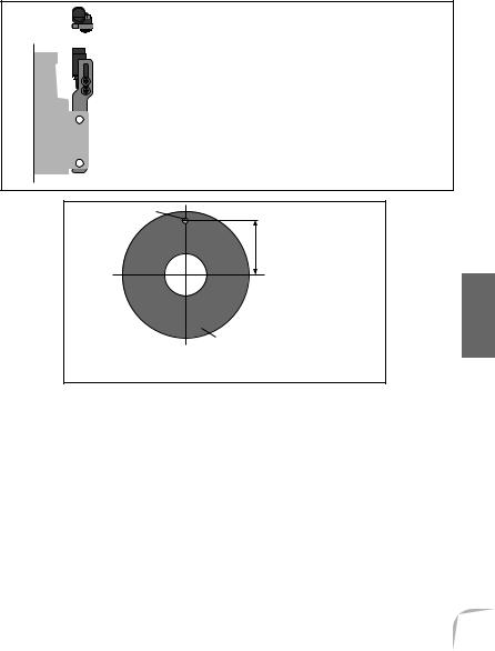
Magnet
Distance from center of engine shaft
Cooling fan
Magnet mounting position
Magnet mounting method
The tables below show the magnet mounting position (example) for each en-
gine. |
|
|
|
|
60 engine |
|
30 engine |
||
|
|
|
|
|
Mounting |
Distance from |
|
Mounting |
Distance from |
center of |
|
center of |
||
position |
|
position |
||
engine shaft |
|
engine shaft |
||
|
|
|
||
Needle side |
27.1-28.8mm |
|
Needle side |
22.0-24.0mm |
|
|
|
|
|
With a Kyosho 60 helicopter, do not use a stay. Mount the sensor directly to the
helicopter frame.
ASSEMBLY & ADJUSTMENT
17
Loading...