


 Loading...
i
Manufacturer
FUJIFILM SonoSite, Inc.
21919 30th Drive SE
Bothell, WA 98021-3904 USA
Telephone: 1-888-482-9449 or 1-425-951-1200 Fax: 1-425-951-1201
EC Authorized Representative
FUJIFILM SonoSite B.V.
Joop Geesinkweg 140
1114 AB Amsterdam, The Netherlands
Australia Sponsor
FUJIFILM SonoSite Australasia Pty Ltd
114 Old Pittwater Rd
Brookvale, New South Wales 2100, Australia
Caution: Federal (United States) law restricts this device to sale by or on the order of a physician.
SonoSite SII, SonoHD2, SonoMB, SonoSite and the SONOSITE logo are registered and unregistered trademarks of FUJIFILM SonoSite, Inc. in various jurisdictions.
DICOM is the registered trademark of the National Electrical Manufacturers Association for its standards publications relating to digital communications of medical information.
Non-SonoSite product names may be trademarks or registered trademarks of their respective owners.
FUJIFILM is a registered and unregistered trademark of FUJIFILM Corporation in various jurisdictions.
The FUJIFILM SonoSite ultrasound system(s) referenced in this document may be covered by one or more of the following U.S. patents: US 8,861,822; US 8,858,436; US 8,834,372; US 8,805,047; US 8,439,840; US 8,398,408; US 8,355,554; US 8,216,146; US 8,213,467; US 8,147,408; US 8,137,278; US 8,088,071; US 8,066,642; US 8,052,606; US 7,819,807; US 7,804,970; US 7,740,586; US 7,686,766; US 7,604,596; US 7,591,786; US 7,588,541; US 7,534,211; US 7,449,640; US 7,169,108; US 6,962,566; US 6,648,826; US 6,575,908; US 6,569,101; US 6,471,651; US 6,416,475; US 6,383,139; US 6,364,839; US 6,203,498; US 6,135,961; US 5,893,363; US 5,817,024; US 5,782,769; US 5,722,412; AU: 730822; AU: 727381; CA: 2,372,152; CA: 2,371,711; CN 103237499B; CN 101231457B; CN 98108973.9; CN 98106133.8; CN 97113678.5; DE 69831698.3; DE 69830539.6; DE 69730563.5; DE 602004027882.3; DE 602004023816.3; DE 60034670.6; DE 60029777.2; EP 1589878; EP 1552792; EP 1180971; EP 0875203; EP 0815793; EP 1180970; EP 0881492; ES 2229318; ES 159878; ES 1552792; ES 0881492; FR 158978; FR 1552792; FR 1180970; FR 0881492; FR 0875203; FR 0815793; GB 158978; GB 1552792; GB 1180971; GB 1180970; GB 0881492; GB 0875203;GB 0815793; IT 1589878; IT 1552792; IT 0881492; IT 0815793; JP 5782428; JP 4696150; KR 532359; KR 528102; NO 326814; NO 326202 and pending.
P22358-02 10/2018
Copyright © 2018 FUJIFILM SonoSite, Inc.
All rights reserved.
ii

Introduction ........................................................................................ |
1 |
Audience .............................................................................................. |
1 |
Contact Information.............................................................................. |
1 |
Conventions ......................................................................................... |
2 |
Labeling symbols.................................................................................. |
2 |
............................................................................................................. |
7 |
System Specifications .......................................................................... |
7 |
System Dimensions.............................................................................. |
7 |
Display Dimensions.............................................................................. |
7 |
Environmental limits ............................................................................. |
7 |
Operating (system, battery, and transducer)........................................ |
7 |
Shipping and storage (system and transducer).................................... |
7 |
Shipping and storage (battery)............................................................. |
7 |
Electrical specifications ........................................................................ |
7 |
Battery specifications ........................................................................... |
8 |
Imaging Modes..................................................................................... |
8 |
Image and Clip Storage........................................................................ |
8 |
Compatible accessories and peripherals ............................................. |
8 |
Safety................................................................................................... |
11 |
Electrical safety.................................................................................... |
11 |
Electrical safety classification............................................................... |
13 |
Equipment safety.................................................................................. |
13 |
Battery safety ....................................................................................... |
14 |
Clinical safety....................................................................................... |
15 |
Hazardous materials ............................................................................ |
15 |
Electromagnetic compatibility............................................................... |
16 |
Electrostatic discharge ......................................................................... |
16 |
Separation distance.............................................................................. |
17 |
Guidance and manufacturer’s declaration............................................ |
18 |
Immunity testing requirements ............................................................. |
21 |
Standards............................................................................................. |
21 |
Electromechanical Safety Standards ................................................... |
21 |
EMC Standards Classification.............................................................. |
21 |
Acoustic standards............................................................................... |
21 |
Biocompatibility standards.................................................................... |
21 |
Airborne Equipment Standards ............................................................ |
22 |
DICOM Standard.................................................................................. |
22 |
HIPAA Standard................................................................................... |
22 |
System Overview................................................................................ |
23 |
About the System................................................................................. |
23 |
Theory of Operation ............................................................................. |
23 |
Description of Operating Modes........................................................... |
25 |
Additional System Feature Performances............................................ |
26 |
Front End Overview.............................................................................. |
27 |
Back End Overview.............................................................................. |
28 |
Control Subsystem............................................................................... |
29 |
Power Supply and Control.................................................................... |
30 |
Battery Pack (VBAT)............................................................................ |
30 |
1

Battery Charger.................................................................................... |
31 |
DICOM ................................................................................................. |
31 |
Troubleshooting................................................................................. |
33 |
System and Subsystem Diagnosis....................................................... |
33 |
System Repair...................................................................................... |
34 |
Test Equipment.................................................................................... |
34 |
Failure (Assert) Codes ......................................................................... |
34 |
Verifying a System Assert Code .......................................................... |
34 |
DICOM ................................................................................................. |
35 |
User Interface....................................................................................... |
36 |
Battery.................................................................................................. |
36 |
Replacement Procedures.................................................................. |
37 |
Required Tools..................................................................................... |
37 |
User Interface Removal ....................................................................... |
37 |
Required Parts ..................................................................................... |
37 |
User Interface Removal ....................................................................... |
37 |
User Interface Parts Transfer............................................................... |
40 |
Install User Interface ............................................................................ |
42 |
Base Assembly Disassembly for Repair and/or Replacement............. |
43 |
Required Tools..................................................................................... |
44 |
Power Button PCA Replacement......................................................... |
44 |
Required Parts ..................................................................................... |
44 |
Power Button PCA Removal................................................................ |
44 |
Power Button PCA Replacement......................................................... |
44 |
Back Enclosure Replacement.............................................................. |
45 |
Back Enclosure Removal..................................................................... |
45 |
Back Enclosure Replacement.............................................................. |
45 |
Internal Mini-Dock Replacement.......................................................... |
46 |
Required Parts ..................................................................................... |
46 |
Internal Mini-Dock Removal................................................................. |
46 |
Internal Mini-Dock Replacement.......................................................... |
47 |
DTC/STC Replacement ....................................................................... |
47 |
Required Parts ..................................................................................... |
47 |
DTC Removal....................................................................................... |
48 |
DTC Replacement................................................................................ |
49 |
Dual Fan Cable Assembly Replacement ............................................. |
50 |
Required Parts ..................................................................................... |
50 |
Dual Fan Cable Assembly Removal .................................................... |
50 |
Dual Fan Cable Assembly Replacement ............................................. |
50 |
Power Supply PCBA Removal............................................................. |
51 |
Required Parts ..................................................................................... |
51 |
Power Supply PCBA Removal............................................................. |
51 |
Power Supply PCBA Replacement...................................................... |
51 |
SD Card Replacement ......................................................................... |
52 |
Main PCBA Replacement .................................................................... |
52 |
Required Parts ..................................................................................... |
52 |
Main PCBA Removal ........................................................................... |
53 |
Main PCBA Replacement .................................................................... |
53 |
2

Mid-Frame Replacement...................................................................... |
55 |
Required Parts ..................................................................................... |
55 |
Mid-Frame Replacement...................................................................... |
55 |
Maintenance........................................................................................ |
57 |
Periodic Maintenance........................................................................... |
57 |
Performance Testing.......................................................................... |
59 |
Overview .............................................................................................. |
59 |
Recommend Test Equipment............................................................... |
59 |
Setting Up Performance Tests ............................................................. |
59 |
Basic Operational Tests....................................................................... |
60 |
2D Performance Tests ......................................................................... |
60 |
2D Performance / Image Quality.......................................................... |
60 |
Axial Measurement Accuracy............................................................... |
61 |
Lateral Measurement Accuracy............................................................ |
61 |
Penetration........................................................................................... |
62 |
Additional Performance Tests.............................................................. |
62 |
Color Doppler (Color) ........................................................................... |
62 |
Color Power Doppler (CPD)................................................................. |
63 |
M Mode Imaging................................................................................... |
63 |
Tissue Harmonic Imaging..................................................................... |
63 |
Image Quality Verification Test/Livescan ............................................. |
63 |
Printer................................................................................................... |
64 |
Battery Charging .................................................................................. |
64 |
Video Output ........................................................................................ |
64 |
Replacement Parts List...................................................................... |
65 |
Base Assembly Components ............................................................... |
65 |
Additional Base Assembly Components .............................................. |
67 |
User Interface Components ................................................................. |
68 |
Parts Unique to STC Systems.............................................................. |
69 |
Enclosure Parts.................................................................................... |
70 |
Transducer Nest Frame Assembly....................................................... |
71 |
Ordering Replacement Parts................................................................ |
72 |
Service Event Reporting.................................................................... |
73 |
Service Event Report Form.................................................................. |
74 |
Service Event Report Instructions........................................................ |
75 |
Returning Products to FUJIFILM SonoSite .......................................... |
76 |
Shipping Instructions............................................................................ |
76 |
3

4

Chapter 1: Introduction
Before servicing the SonoSite SII ultrasound system, please read this manual.
The ultrasound system has multiple configurations and feature sets. All are described in this service manual but not every option may apply to your system. System features depend on your system configuration, transducer, and exam type.
Refer to the SII Ultrasound System User Guide for additional information regarding safety, system controls, operation, capabilities, and specifications.
Audience
The intended audience of this manual is properly trained field and in-house service personnel.
Contact Information
Questions and comments are encouraged. FUJIFILM SonoSite is interested in your feedback regarding the service manual. If you encounter difficulty with the system, use the information in this manual to help correct the problem. If the problem is not covered here, contact FUJIFILM SonoSite Technical Support as follows:
Technical Support (USA, Canada) |
1-877-657-8118 |
Technical Support fax: |
1-425-951-6700 |
Technical Support e-mail: |
ffss-service@fujifilm.com |
FUJIFILM SonoSite website: |
www.sonosite.com |
International Technical Support: |
Contact your local representative or call (USA) |
|
+425-951-1330 |
European Service Center |
United Kingdom |
|
Tel: 0044 01462341151 |
|
e-mail: uk-service@fujifilm.com |
|
France |
|
Tel: 0033 01/82880702 |
|
e-mail: ERAF-service@fujifilm.com |
|
Germany |
|
Tel: 0049 069/80884030 |
|
e-mail: ERAF-service@fujifilm.com |
|
Spain |
|
Tel: 0034 911238451 |
|
e-mail: ERAF-service@fujifilm.com |
|
Italy |
|
Tel 0039 02 94753655 |
|
e-mail: ERAF-service@fujifilm.com |
Asia/Pacific |
Tel: (+65) 63805581 |
|
e-mail: FFSS-APACME-service@fujifilm.com |
Chapter 1: Introduction |
1 |

Conventions
These conventions are used in this service manual:
•A WARNING describes precautions necessary to prevent injury or loss of life.
•A Caution describes precautions necessary to protect the products.
•Numbered steps must be performed in a specific order.
•Bulleted lists present information in list format but do not imply a sequence.
Labeling symbols
The following symbols are used on the products, packaging, and containers.
Table 1: Labeling Symbols
Symbol Definition
Alternating Current (AC)
Class 1 device indicating manufacturer’s declaration of conformance with
Annex VII of 93/42/EEC
Class 1 device requiring verification by the Notified Body of sterilization or measurement features, or to a Class IIa, IIb, or III device requiring verification or auditing by the Notified Body to applicable Annex(es) of 93/42/EEC
Attention, see the user guide
Follow instructions for use.
|
Device complies with relevant Australian regulations for electronic devices. |
LOT |
Batch code, date code, or lot code type of control number |
|
|
|
Biological risk |
|
Authorized representative in the European Community |
|
Canadian Standards Association. The “C” and “US” indicators next to this |
|
mark signify that the product has been evaluated to the applicable CSA |
|
and ANSI/UL Standards, for use in Canada and the US, respectively. |
REF |
Catalog number |
|
2Chapter 1: Introduction
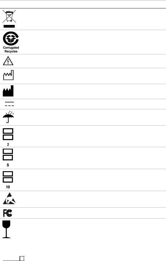
Table 1: Labeling Symbols (Continued)
Symbol Definition
Collect separately from other household waste (see European Commission
Directive 93/86/EEC). Refer to local regulations for disposal.
Corrugated recycle
Dangerous voltage
Date of manufacture
Manufacturer
Direct Current (DC)
Do not get wet.
Do not stack over 2 high.
Do not stack over 5 high.
Do not stack over 10 high.
Electrostatic sensitive devices
Device complies with relevant FCC regulations for electronic devices.
Fragile
|
GEL |
Gel |
|
||
|
|
|
|
|
|
|
|
|
|
Sterilized using irradiation |
|
|
|
STERILE R |
|
||
|
|
|
|
||
|
|
|
|
|
|
|
|
|
|
|
|
Chapter 1: Introduction |
3 |

Table 1: Labeling Symbols (Continued)
|
Symbol |
Definition |
|
|||
|
|
|
|
|
|
|
|
|
|
|
|
Sterilized using ethylene oxide |
|
|
|
STERILE |
EO |
|
||
|
|
|
|
|
|
|
|
|
|
|
|
Hot |
|
|
|
|
|
|
|
|
|
|
|
|
|
Indoor use only. |
|
|
|
|
|
|
|
|
|
|
|
|
|
Non-ionizing radiation |
|
|
|
|
|
|
|
|
|
|
|
|
|
Paper recycle |
|
|
|
|
|
|
|
|
|
|
|
|
|
Serial number type of control number |
|
|
|
SN |
|
|
|
|
|
|
|
|
|
||
|
|
|
|
|
|
|
|
|
|
|
|
Temperature limitation |
|
|
|
|
|
|
|
|
|
|
|
|
|
Atmospheric pressure limitation |
|
|
|
|
|
|
|
|
|
|
|
|
|
Humidity limitation |
|
|
|
|
|
|
|
|
|
|
|
|
|
Submersible. Protected against the effects of temporary immersion. |
|
|
|
|
|
|
|
|
|
|
|
|
|
Water-Tight Equipment. Protected against the effects of extended |
|
|
|
|
|
|
immersion. |
|
|
|
|
|
|
|
|
|
|
|
|
|
Handle transducer with care. |
|
|
|
|
|
|
|
|
|
|
|
|
|
To avoid tipping, do not move the system using the handle on the front of |
|
|
|
|
|
|
the SonoSite SII ultrasound system. |
|
|
|
|
|
|
|
|
|
|
|
|
|
When moving the system, push the stand using the tray assembly. |
|
|
|
|
|
|
|
|
|
|
|
|
|
Type BF patient applied part |
|
|
|
|
|
|
(B = body, F = floating applied part) |
|
|
|
|
|
|
|
|
|
|
|
|
|
Defibrillator proof type CF patient applied part |
|
|
|
|
|
|
|
|
|
|
|
|
|
A mandatory action that the user shall read the accompanying |
|
|
|
|
|
|
documentation for more information. |
|
|
|
|
|
|
|
|
|
|
|
|
|
|
|
4Chapter 1: Introduction
Table 1: Labeling Symbols (Continued)
Symbol Definition
Pollution Control Logo. (Applies to all parts/products listed in the China RoHS disclosure table. May not appear on the exterior of some parts/products because of space limitations.)
China Compulsory Certificate mark (“CCC Mark”). A compulsory safety mark for compliance to Chinese national standards for many products sold in the People’s Republic of China.
Maximum weight load
WARNING: |
WARNING: Connect Only |
Connect Only |
Accessories and Peripherals |
Accessories and |
|
Peripherals |
Recommended by FUJIFILM SonoSite |
Recommended |
|
by FUJIFILM |
|
SonoSite |
|
|
|
Chapter 1: Introduction |
5 |

6Chapter 1: Introduction

Chapter 2:
Specifications
System Specifications
This chapter contains information regarding system specifications and accessory compatibility. The information applies to the ultrasound system, transducers, accessories, and peripherals.
System Dimensions
Height: 17.6 in. (44.7 cm)
Max height with stand: 59.5 in. (151 cm)
Min height with stand: 49 in. (124.5 cm)
Width: 11.3 in. (28.7 cm)
Depth: 4.8 in. (12.2 cm)
Weight:12.5 lbs. (5.7 kg)
Weight with stand 57.5 lbs. (26.1 kg)
Display Dimensions
Length: 9.7 in. (24.6 cm)
Height: 7.3 in. (18.5 cm)
Diagonal: 12.1 in. (30.7 cm)
Environmental limits
Note: The temperature, pressure, and humidity limits apply only to the ultrasound system and transducers.
Operating (system, battery, and transducer)
10–40°C (50–104°F), 15–95% R.H. 700 to 1060hPa (0.7 to 1.05 ATM)
Shipping and storage (system and transducer)
-20–60°C (-4–140°F), 15–95% R.H. 500 to 1060hPa (0.5 to 1.05 ATM)
Shipping and storage (battery)
-20–60°C (-4–140°F), 15–95% R.H. (For storage longer than 30 days, store at or below room temperature.)
500 to 1060hPa (0.5 to 1.05 ATM)
Electrical specifications
Power Supply Input: |
100-240 VAC, 50/60 Hz, 2.0 A Max @ 100 VAC. |
|
Power Supply Output 1: |
15 |
VDC, 5.0A Max (system) |
Power Supply Output 2: |
12 |
VDC, 2.3A Max (battery) |
Combined output not exceeding 75W.
Chapter 2: |
7 |

Battery specifications
The battery is comprised of six lithium-ion cells plus electronics, a temperature sensor, and battery contacts. Run time is up to two hours, depending on imaging mode and display brightness.
Imaging Modes
2D (256 gray shades)
Color power Doppler (CPD) (256 colors)
Color Doppler (Color) (256 colors)
M Mode
Tissue Harmonic Imaging (THI)
Image and Clip Storage
The number of images and clips you can save varies with imaging mode and file format.
Compatible accessories and peripherals
FUJIFILM SonoSite has tested the SonoSite SII ultrasound system with the following accessories and peripherals and has demonstrated compliance to the requirements of IEC60601-1-2:2007.
You may use these FUJIFILM SonoSite accessories and third-party peripherals with the SonoSite SII ultrasound system.
WARNING: |
Use of the accessories with medical systems other than the SonoSite SII |
||
|
ultrasound system may result in increased emissions or decreased |
||
|
immunity of the medical system. |
|
|
WARNING: |
Use of accessories other than those specified may result in increased |
||
|
emissions or decreased immunity of the ultrasound system. |
||
|
|
||
Accessories and peripherals compatible with SonoSite SII ultrasound system |
|||
|
|
|
|
Description |
|
Part Number |
Maximum Cable Length |
|
|
|
|
C11x transducer |
|
P07678 |
6.0 ft/1.8 m |
|
|
|
|
C35x transducer |
|
P21981 |
6.0 ft/1.8 m |
|
|
|
|
rC60xi transducer |
|
P21070 |
5.5 ft/1.7 m |
|
|
|
|
rC60xi transducer armored |
P21636 |
5.5 ft/1.7 m |
|
|
|
|
|
rP19x transducer |
|
P21015 |
6.0 ft/1.8 m |
|
|
|
|
rP19x transducer armored |
P21556 |
6.0 ft/1.8 m |
|
|
|
|
|
HFL38xi transducer |
|
P20311 |
5.5 ft/1.7 m |
|
|
|
|
HFL38xi transducer armored |
P20377 |
5.5 ft/1.7 m |
|
|
|
|
|
HFL50x transducer |
|
P07693 |
5.5 ft/1.7 m |
|
|
|
|
HSL25x |
|
P20679 |
7.5 ft/2.3 m |
|
|
|
|
ICTx transducer |
|
P07690 |
5.5 ft/1.7 m |
|
|
|
|
L25x transducer |
|
P07691 |
7.5 ft/2.3 m |
|
|
|
|
8Chapter 2:

Accessories and peripherals compatible with SonoSite SII ultrasound system (Continued)
L25x transducer armored |
P22950 |
7.5 ft/2.3 m |
|
|
|
L38xi transducer |
P12742 |
5.5 ft/1.7 m |
|
|
|
L38xi transducer armored |
P19626 |
5.5 ft/1.7 m |
|
|
|
L52x transducer (Vet) |
V00033 |
7.5 ft/2.3 m |
|
|
|
L52x transducer armored (Vet) |
V20962 |
7.5 ft/2.3 m |
|
|
|
P10x transducer |
P07696 |
6.0 ft/ 1.8m |
|
|
|
P11x transducer |
P16665 |
6.5 ft/2.0 m |
|
|
|
Bar code scanner |
P14166 |
4.8 ft/1.5 m |
|
|
|
Kit, PowerPack |
P13559 |
— |
|
|
|
Battery for PowerPack |
P13123 |
— |
|
|
|
Black & white printer |
P13745 |
— |
|
|
|
Hybrid black & white printer |
P20006 |
|
|
|
|
Black & white printer power |
— |
3.3 ft/1 m |
cable |
|
|
|
|
|
Black & white printer USB |
— |
10.8 ft/3.3 m |
cable |
|
|
|
|
|
Dual USB Footswitch |
P14689 |
9.8 ft/3.0 m |
|
|
|
SII Stand |
P21432 |
— |
|
|
|
Storage bin kit, Universal/Edge |
P22048 |
— |
stands |
|
|
|
|
|
Power cord (system) |
P00848 (USA) |
10 ft/3 m |
|
|
|
Power Supply/Battery Charger |
P09823 |
6.8 ft/ 2 m |
|
|
|
PowerPark |
P12822 |
— |
|
|
|
USB wireless adapter |
P17725 |
— |
|
|
|
EU compliant wireless adapter |
P22625 |
|
|
|
|
SII Battery Pack |
P20664 |
— |
|
|
|
Wireless mounting kit |
P17724 |
|
|
|
|
Chapter 2: |
9 |

10 Chapter 2:

Chapter 3: Safety
This chapter contains electrical and clinical safety information required by regulatory agencies. The information applies to the ultrasound system, transducers, accessories, and peripherals.
Electrical safety
This system meets EN60601-1, Class I/internally-powered equipment requirements and Type BF and Type CF isolated patient-applied parts safety requirements.
This system complies with the applicable medical equipment requirements published in the Canadian Standards Association (CSA), European Norm Harmonized Standards, and Underwriters Laboratories (UL) safety standards. See “Standards” on page 21.
For maximum safety observe the following warnings and cautions.
WARNING: To avoid the risk of injury, do not operate the system in the presence of flammable gasses or anesthetics. Explosion can result.
WARNING: To avoid the risk of electrical shock or injury, do not open the system enclosures. All internal adjustments and replacements, except battery replacement, must be made by a qualified technician.
WARNING: To avoid the risk of electrical shock:
•This equipment must be connected only to a supply mains with protective earth.
•Use only properly grounded equipment. Shock hazards exist if the power supply is not properly grounded. Grounding reliability can be achieved only when equipment is connected to a receptacle marked “Hospital Only” or “Hospital Grade” or equivalent. The grounding wire must not be removed or defeated.
•When using the system in an environment where the integrity of the protective earth conductor arrangement is in doubt, operate the system on battery power only and disconnect the power supply.
•Do not let the bar code scanner touch the patient.
•Do not touch any of the following:
•The power supply and the patient at the same time
•The ungrounded signal input/output connectors on the back of the ultrasound system
•The system battery contacts (inside the battery compartment)
•The system transducer connector when the transducer is disconnected
Chapter 3: Safety |
11 |
•Do not connect the system power supply or docking system to a multiple portable socket outlet (MPSO) or extension cord.
•Before using the transducer, inspect the transducer face, housing, and cable. Do not use the transducer if the transducer or cable is damaged.
•Always disconnect the power supply from the system before cleaning the system.
•Do not use any transducer that has been immersed beyond the specified cleaning or disinfection level. See Chapter 7, “Maintenance”
•Use only accessories and peripherals recommended by FUJIFILM SonoSite, including the power supply. Connection of accessories and peripherals not recommended by FUJIFILM SonoSite could result in electrical shock. Contact FUJIFILM SonoSite or your local representative for a list of accessories and peripherals available from or recommended by FUJIFILM SonoSite.
WARNING: To avoid the risk of electrical shock and fire hazard:
•Inspect the power supply, AC power cords, cables, and plugs on a regular basis. Ensure that they are not damaged.
•The power cord set that connects the power supply of the ultrasound system or the stand to mains power must only be used with the power supply or docking system, and cannot be used to connect other devices to mains power.
WARNING: To prevent injury to the operator/bystander, the transducer must be removed from patient contact before the application of a high-voltage defibrillation pulse.
WARNING: To avoid possible electrical shock or electromagnetic interference, verify proper operation and compliance with relevant safety standards for all equipment before clinical use. Connecting additional equipment to the ultrasound system constitutes configuring a medical system. FUJIFILM SonoSite recommends verifying that the system, all combinations of equipment, and accessories connected to the ultrasound system comply with JACHO installation requirements and/or safety standards such as AAMI-ES1, NFPA 99 OR IEC Standard 60601-1-1 and electromagnetic compatibility standard IEC 60601-1-2 (Electromagnetic compatibility), and are certified according to IEC Standard 60950 (Information Technology Equipment (ITE)).
Caution: Do not use the system if an error message appears on the LCD display. Note the error code and call FUJIFILM SonoSite Technical Support for further assistance.
Caution: To avoid increasing the system and transducer connector temperature, do not block the airflow to the ventilation holes on the side of the system.
12 Chapter 3: Safety

Electrical safety classification
Class I equipment |
The ultrasound system is classified as Class I equipment |
|
when powered from the external power supply or mounted |
|
on the stand because the external power supply is a Class |
|
1 protectively earthed power supply. |
|
The stand has no protective earth. Ground bond testing is |
|
not applicable to the ultrasound system or the stand. |
|
Note:AC powered peripherals that may be used with the system |
|
are Class I and are individually protectively earthed. Ground bond |
|
testing may be conducted on each AC powered peripheral. |
Internally powered |
Ultrasound system not connected to the power supply |
equipment |
(battery only) |
Type BF applied parts |
Ultrasound transducers |
Type CF applied parts |
ECG module/ECG leads |
IPX-7 (watertight |
Ultrasound transducers |
equipment) |
|
Non AP/APG |
Ultrasound system power supply, docking system, and |
|
peripherals. Equipment is not suitable for use in the |
|
presence of flammable anaesthetics. |
Equipment safety
To protect your ultrasound system, transducers, and accessories, follow these precautions.
Caution: Excessive bending or twisting of cables can cause a failure or intermittent operation.
Caution: Improper cleaning or disinfecting of any part of the system can cause permanent damage. For cleaning and disinfecting instructions, see Chapter 7, “Maintenance”
Caution: Do not submerge the transducer connector in solution. The cable is not liquid-tight beyond the transducer connector/cable interface.
Caution: Do not use solvents such as thinner or benzene, or abrasive cleaners on any part of the system.
Caution: Remove the battery from the system if the system is not likely to be used for a month or more.
Caution: Do not spill liquid on the system.
Chapter 3: Safety |
13 |
Battery safety
To prevent the battery from bursting, igniting, or emitting fumes and causing personal injury or equipment damage, observe the following precautions.
WARNING: The battery has a safety device. Do not disassemble or alter the battery.
WARNING: Charge the batteries only when the ambient temperature is between 0° and 40°C (32° and 104°F).
WARNING: Do not short-circuit the battery by directly connecting the positive and negative terminals with metal objects.
WARNING: Do not touch battery contacts.
WARNING: Do not heat the battery or discard it in a fire.
WARNING: Do not expose the battery to temperatures over 60°C (140°F). Keep it away from fire and other heat sources.
WARNING: Do not charge the battery near a heat source, such as a fire or heater. WARNING: Do not leave the battery in direct sunlight.
WARNING: Do not pierce the battery with a sharp object, hit it, or step on it. WARNING: Do not use a damaged battery.
WARNING: Do not solder a battery.
WARNING: The polarity of the battery terminals isfixed and cannot be switched or reversed. Do not force the battery into the system.
WARNING: Do not connect the battery to an electrical power outlet.
WARNING: Do not continue recharging the battery if it does not recharge after two successive six hour charging cycles.
WARNING: Do not ship a damaged battery without instructions from FUJIFILM SonoSite Technical Support. (See “Contact Information” on page 1.)
WARNING: If the battery leaks or emits an odor, remove it from all possible flammable sources.
WARNING: Periodically check to make sure that the battery charges fully. If the battery fails to charge fully, replace it.
Caution: To avoid the battery becoming damaged and causing equipment damage, observe the following precautions:
•Do not immerse the battery in water or allow it to get wet.
•Do not put the battery into a microwave oven or pressurized container.
•If the battery emits an odor or heat, is deformed or discolored, or in any way appears abnormal during use, recharging or storage, immediately remove it and stop using it. If you have any questions about the battery, consult FUJIFILM SonoSite or your local representative.
•Store the battery between -20°C (-4°F) and 60°C (140°F).
•Use only FUJIFILM SonoSite batteries.
•Do not use or charge the battery with non-FUJIFILM SonoSite equipment. Only charge the battery with the system.
14 Chapter 3: Safety
Clinical safety
WARNING: Non-medical (commercial) grade peripheral monitors have not been verified or validated by FUJIFILM SonoSite as being suitable for diagnosis.
WARNING: To avoid the risk of a burn hazard, do not use the transducer with high frequency surgical equipment. Such a hazard may occur in the event of a defect in the high frequency surgical neutral electrode connection.
WARNING: Do not use the system if it exhibits erratic or inconsistent behavior. Discontinuities in the scanning sequence are indicative of a hardware failure that must be corrected before use.
WARNING: Some transducer sheaths contain natural rubber latex and talc, which can cause allergic reactions in some individuals. Refer to 21 CFR 801.437, User labeling for devices that contain natural rubber.
WARNING: Perform ultrasound procedures prudently. Use the ALARA (as low as reasonably achievable) principle and follow the prudent use information concerning MI and TI.
WARNING: FUJIFILM SonoSite does not currently recommend a specific brand of acoustic standoff. If an acoustic standoff is used, it must have a minimum attenuation of .3dB/cm/MHz.
WARNING: Some FUJIFILM SonoSite transducers are approved for intraoperative applications if a market-cleared sheath is used.
WARNING: To avoid injury and reduce risk of infection to the patient, observe the following:
•Follow Universal Precautions when inserting and maintaining a medical device for interventional and intraoperative procedures.
•Appropriate training in interventional and intraoperative procedures as dictated by current relevant medical practices as well as in proper operation of the ultrasound system and transducer is required. During vascular access, the potential exists for serious complications including without limitation the following: pneumothorax, arterial puncture, guidewire misplacement, and risks normally associated with local or general anesthesia, surgery, and post-operative recovery.
WARNING: To avoid device damage or patient injury, do not use the P10x or rP19x needle guide bracket on patients with pacemakers or medical electronic implants. The needle guide bracket for the P10x and rP19x transducers contains a magnet that is used to ensure the bracket is correctly oriented on the transducer. The magnetic field in direct proximity to the pacemaker or medical electronic implant may have an adverse effect.
Hazardous materials
WARNING: Products and accessories may contain hazardous materials. Ensure that products and accessories are disposed of in an environmentally responsible manner and meet federal and local regulations for disposing hazardous materials.
Chapter 3: Safety |
15 |
Electromagnetic compatibility
The ultrasound system has been tested and found to comply with the electromagnetic compatibility (EMC) limits for medical devices to IEC 60601-1-2:2001. These limits are designed to provide reasonable protection against harmful interference in a typical medical installation.
WARNING: The Sonosite SII ultrasound system should not be used adjacent to or stacked with other equipment. If such use occurs, verify that the SonoSite SII ultrasound system operates normally in that configuration.
Caution: Medical electrical equipment requires special precautions regarding EMC and must be installed and operated according to these instructions. Portable and mobile RF communications equipment can affect the ultrasound system.
Electromagnetic interference (EMI) from other equipment or interference sources could result in performance disruption of the ultrasound system. Evidence of disruption may include image degradation or distortion, erratic readings, equipment ceasing to operate, or other incorrect functioning. If this occurs, survey the site to determine the source of disruption, and take the following actions to eliminate the source(s).
•Turn equipment in the vicinity off and on to isolate disruptive equipment.
•Relocate or re-orient interfering equipment.
•Increase distance between interfering equipment and your ultrasound system.
•Manage use of frequencies close to ultrasound system frequencies.
•Remove devices that are highly susceptible to EMI.
•Lower power from internal sources within facility control (such as paging systems).
•Label devices susceptible to EMI.
•Educate clinical staff to recognize potential EMI-related problems.
•Eliminate or reduce EMI with technical solutions (such as shielding).
•Restrict use of personal communicators (cell phones, computers) in areas with devices susceptible to EMI.
•Share relevant EMI information with others, particularly when evaluating new equipment purchases which may generate EMI.
•Purchase medical devices that comply with IEC 60601-1-2 EMC Standards.
Caution: To avoid the risk of increased electromagnetic emissions or decreased immunity, use only accessories and peripherals recommended by FUJIFILM SonoSite. Connection of accessories and peripherals not recommended by FUJIFILM SonoSite to the ultrasound system may result in malfunction of the ultrasound system or other medical electrical devices in the area. Contact FUJIFILM SonoSite or your local representative for a list of accessories and peripherals available from or recommended by FUJIFILM SonoSite. See the FUJIFILM SonoSite accessories user guide.
Electrostatic discharge
Caution: Electrostatic discharge (ESD), or static shock, is a naturally occurring phenomenon. ESD is common in conditions of low humidity, which can be caused by heating or air conditioning. ESD is a discharge of the electrical energy from a charged body to a lesser or non-charged body. The degree of discharge can be significant enough to cause damage to a transducer or an ultrasound system. The following precautions can help reduce ESD: anti-static spray on carpets, anti-static spray on linoleum, and anti-static mats.
16 Chapter 3: Safety

Separation distance
Recommended separation distances between portable and mobile RF communications equipment and the SonoSite SII ultrasound system
The SonoSite SII ultrasound system is intended for use in an electromagnetic environment in which radiated radio frequency (RF) disturbances are controlled. The customer or the user of the SonoSite SII ultrasound system can help prevent electromagnetic interference by maintaining a minimum distance between portable and mobile RF communications equipment (transmitters) and the SonoSite SII ultrasound system as recommended below, according to the maximum output power of the communications equipment.
Rated maximum output power of transmitter
Watts
Separation distance according to frequency of transmitter m
150 kHz to 80 MHz |
80 MHz to 800 MHz |
800 MHz to 2.5 GHz |
d=1.2 P |
d=1.2 P |
d=2.3 P |
0.01 |
0.12 |
0.12 |
0.23 |
|
|
|
|
0.1 |
0.38 |
0.38 |
0.73 |
|
|
|
|
1 |
1.2 |
1.2 |
2.3 |
|
|
|
|
10 |
3.8 |
3.8 |
7.3 |
|
|
|
|
100 |
12 |
12 |
23 |
For transmitters rated at a maximum output power not listed above, the recommended separation distance (d) in meters (m) can be estimated using the equation applicable to the frequency of the transmitter, where P is the maximum output power rating of the transmitter in watts (W) according to the transmitter manufacturer.
Note: At 80 MHz and 800 MHz, the separation distance for the higher frequency range applies.
These guidelines may not apply in all situations. Electromagnetic propagation is affected by absorption and reflection from structures, objects, and people.
Chapter 3: Safety |
17 |
Guidance and manufacturer’s declaration
WARNING: Other equipment, even equipment that complies with CISPR emission requirements, can interfere with the SonoSite SII ultrasound system.
The SonoSite SII wireless adapter contains an IEEE 802.11 transmitter that utilizes the ISM frequency band from 2.412 to 2.4835 GHz and implements two methods of transmission:
•IEEE 802.11b with Complementary Code Keying (CCK), Differential Quaternary Phase Shift Keying (DQPSK), and Differential Binary Phase Shift Keying (DBPSK) at 16 dB
•IEEE 802.11g with Orthogonal Frequency Division Multiplexing (OFDM) at 13 dBm
Guidance and Manufacturer’s Declaration - Electromagnetic Emissions
The SonoSite SII ultrasound system is intended for use in the electromagnetic environment specified below. The customer or the user of the SonoSite SII ultrasound system should assure that it is used in such an environment.
Emissions Test |
Compliance |
Electromagnetic Environment |
|
|
|
RF emissions |
Group 1 |
The SonoSite SII ultrasound system uses RF |
ClSPR 11 |
|
energy only for its internal function. Therefore, its |
|
|
RF emissions are very low and are not likely to |
|
|
cause any interference in nearby electronic |
|
|
equipment. |
RF emissions |
Class A |
ClSPR 11 |
|
|
|
Harmonic emissions |
Class A |
IEC 61000-3-2 |
|
|
|
Voltage |
Complies |
fluctuations/flicker |
|
emissions |
|
IEC 61000-3-3 |
|
The SonoSite SII ultrasound system is suitable for use in all establishments other than domestic and those directly connected to the public low-voltage power supply network which supplies buildings used for domestic purposes.±
Guidance and Manufacturer’s Declaration - Electromagnetic Immunity
The SonoSite SII ultrasound system is intended for use in the electromagnetic environment specified below. The customer or the user of the SonoSite SII ultrasound system should assure that it is used in such an environment.
Immunity |
IEC 60601 Test |
Compliance |
Electromagnetic |
Test |
Level |
Level |
Environment |
Electrostatic |
±6.0KV contact |
±6.0KV contact |
Discharge |
±8.0KV air |
±8.0KV air |
(ESD) |
|
|
IEC 61000-4-2 |
|
|
Floors should be wood, concrete or ceramic tile. If floors are covered with synthetic material, the relative humidity should be at least 30%.
18 Chapter 3: Safety

Guidance and Manufacturer’s Declaration - Electromagnetic Immunity (Continued)
The SonoSite SII ultrasound system is intended for use in the electromagnetic environment specified below. The customer or the user of the SonoSite SII ultrasound system should assure that it is used in such an environment.
Immunity |
IEC 60601 Test |
Compliance |
Electromagnetic |
|
Test |
Level |
Level |
Environment |
|
|
|
|
|
|
Electrical fast |
±2KV for power |
±2KV for power |
Mains power quality should |
|
Transient burst |
supply lines |
supply lines |
be that of a typical |
|
IEC 61000-4-4 |
±1KV for |
±1KV for |
commercial or hospital |
|
|
input/output lines |
input/output lines |
environment. |
|
|
|
|
|
|
Surge |
±1KV line(s) to |
±1KV line(s) to |
Mains power quality should |
|
IEC 61000-4-5 |
line(s) |
line(s) |
be that of a typical |
|
|
±2KV line(s) to earth |
±2KV line(s) to |
commercial or hospital |
|
|
|
earth |
environment. |
|
|
|
|
|
|
Voltage dips, |
>5% UT |
>5% UT |
Mains power quality should |
|
short |
(>95% dip in UT) for |
(>95% dip in UT) |
be that of a typical |
|
interruptions |
commercial or hospital |
|||
0.5 cycle |
for 0.5 cycle |
|||
and voltage |
environment. If the user of |
|||
40% UT |
40% UT |
|||
variations on |
the SonoSite SII ultrasound |
|||
power supply |
(60% dip in UT) for 5 |
(60% dip in UT) |
system requires continued |
|
input lines |
cycles |
for 5 cycles |
operation during power |
|
IEC |
70% UT |
70% UT |
mains interruptions, it is |
|
61000-4-11 |
(30% dip in UT) for |
(30% dip in UT) |
recommended that the |
|
|
SonoSite SII ultrasound |
|||
|
25 cycles |
for 25 cycles |
system be powered from an |
|
|
>5% UT |
>5% UT |
uninterruptible power supply |
|
|
(>95% dip in UT) for |
(>95% dip in UT) |
or a battery. |
|
|
5s |
for 5s |
|
|
|
|
|
|
|
Power |
3 A/m |
3 A/m |
Power frequency magnetic |
|
Frequency |
|
|
fields should be at levels |
|
Magnetic Field |
|
|
characteristic of a typical |
|
IEC 61000-4-8 |
|
|
location in a typical |
|
|
|
|
commercial or hospital |
|
|
|
|
environment. |
|
|
|
|
|
|
Conducted RF |
3 Vrms |
3 Vrms |
Portable and mobile RF |
|
IEC 61000-4-6 |
150 kHz to 80 MHz |
|
communications equipment |
|
|
|
|
should be used no closer to |
|
|
|
|
any part of the SonoSite SII |
|
|
|
|
ultrasound system including |
|
|
|
|
cables, than the |
|
|
|
|
recommended separation |
|
|
|
|
distance calculated from the |
|
|
|
|
equation applicable to the |
|
|
|
|
frequency of the transmitter. |
|
|
|
|
Recommended Separation |
|
|
|
|
Distance |
|
|
|
|
d = 1.2 P |
|
|
|
|
|
Chapter 3: Safety |
19 |
Guidance and Manufacturer’s Declaration - Electromagnetic Immunity (Continued)
The SonoSite SII ultrasound system is intended for use in the electromagnetic environment specified below. The customer or the user of the SonoSite SII ultrasound system should assure that it is used in such an environment.
Immunity |
IEC 60601 Test |
Compliance |
Electromagnetic |
Test |
Level |
Level |
Environment |
|
|
|
|
Radiated RF |
3 Vim |
3 V/m |
d = 1.2 P |
IEC 61000-4-3 80 MHz to 2.5 GHz |
|
80 MHz to 800 MHz |
|
|
|
|
|
|
|
|
d = 2.3 P |
|
|
|
800 MHz to 2,5 GHz |
|
|
|
Where P is the maximum |
|
|
|
output power rating of the |
|
|
|
transmitter in watts (W) |
|
|
|
according to the transmitter |
|
|
|
manufacturer and d is the |
|
|
|
recommended separation |
|
|
|
distance in meters (m). |
|
|
|
|
Radiated RF |
|
|
Field strengths from fixed |
IEC 61000-4-3 |
|
|
RF transmitters, as |
(continued) |
|
|
determined by an |
|
|
electromagnetic Site |
|
|
|
|
|
surveya, should be less than the compliance level in each frequency rangeb.
Interference may occur in the vicinity of equipment marked with the following symbol:
Note:UT is the AC mains voltage prior to application of the test level.
At 80 MHz and 800 MHz, the higher frequency range applies.
These guidelines may not apply in all situations. Electromagnetic propagation is affected by absorption and reflection from structures, objects and people.
a.Field strengths from fixed transmitters such as base stations for radio (cellular/cordless) telephones and land mobile radios, amateur radio, AM and FM radio broadcast and TV broadcast cannot be predicted theoretically with accuracy. To assess the electromagnetic environment due to fixed RF transmitters, an electromagnetic site survey should be considered. If the measured field strength in the location in which the FUJIFILM SonoSite ultrasound system is used exceeds the applicable RF compliance level above, the FUJIFILM SonoSite ultrasound system should be observed to verify normal operation. If abnormal performance is observed, additional measures may be necessary, such as re-orienting or relocating the FUJIFILM SonoSite ultrasound system.
b.Over the frequency range 150 kHz to 80 MHz, field strengths should be less than 3 V/m.
FCC Caution: Changes or modifications not expressly approved by the party responsible for compliance could void the user’s authority to operate the equipment.
This device complies with part 15 of the FCC Rules. Operation is subject to the following two conditions:
•This device may not cause harmful interference.
•This device must accept any interference received, including interference that may cause undesired operation.
20 Chapter 3: Safety
Loading...