


 Loading...
Service Manual
Stand and Desktop Systems
i

ii

Legal Notices
Manufacturer
FUJIFILM SonoSite, Inc.
21919 30th Drive SE
Bothell, WA 98021-3904 USA
T: (888) 482-9449 or (425) 951-1200 F: (425) 951-1201
EC Authorized Representative
FujiFilm SonoSite B.V.
Joop Geesinkweg 140
1114 AB Amsterdam, The Netherlands
Australia Sponsor
FUJIFILM SonoSite Australasia Pty Ltd
114 Old Pittwater RD
Brookvale, New South Wales 2100, Australia
Caution: United States federal law restricts this device to sale by or on the order of a physician.
SonoMB, SonoSite, Steep Needle Profiling, X-Porte, and the SonoSite logo are registered (in some jurisdictions) and unregistered trademarks owned by FUJIFILM SonoSite, Inc. in various jurisdictions.
DICOM is the registered trademark of the National Electrical Manufacturers Association.
All other trademarks are the property of their respective owners.
Patents: US 8,216,146; US 8,213,467; US 8,147,408; US 8,137,278; US 8,088,071; US 8,066,642; US 8,052,606; US 7,819,807; US 7,804,970; US 7,740,586; US 7,686,766; US 7,604,596; US 7,591,786; US 7,588,541; US 7,534,211; US 7,449,640; US 7,169,108; US 6,962,566; US 6,648,826; US 6,575,908; US 6,569,101; US 6,471,651; US 6,416,475; US 6,383,139; US 6,364,839; US 6,203,498; US 6,135,961; US 5,893,363 ; US 5,817,024; US 5,782,769; US 5,722,412; AU: 730822; AU: 727381; CA: 2,372,152; CA: 2,371,711; CN 98108973.9; CN: 98106133.8; CN: 97113678.5; DE: 69831698.3; DE: 69830539.6; DE: 69730563.5; DE: 602004027882.3; DE: 602004023816.3; DE: 60034670.6; DE: 60029777.2; EP: 1589878; EP: 1552792; EP: 1180971; EP: 0875203; EP: 0815793; EP 1180970; EP 0881492; ES: 2229318; ES: 159878; ES: 1552792; ES: 0881492; FR: 158978; FR: 1552792; FR: 1180970; FR: 0881492; FR: 0875203; FR: 0815793; GB: 158978; GB: 1552792; GB: 1180971; GB: 1180970; GB: 0881492; GB: 0875203; GB: 0815793; IT: 1589878; IT: 1552792; IT: 0881492; IT: 0815793; JP: 4696150; KR: 532359; KR: 528102; NO: 326814; NO: 326202
Copyright © 2018 FUJIFILM SonoSite Inc, Inc. All rights reserved.
P16620-01
iii

iv

Table of Contents |
|
Introduction ................................................................................. |
1 |
Audience.................................................................................................................. |
1 |
Contact Information ................................................................................................. |
1 |
Terms and symbols ................................................................................................. |
2 |
Labeling symbols..................................................................................................... |
2 |
Specifications.............................................................................. |
3 |
Specifications........................................................................................................... |
3 |
System Specifications ............................................................................................. |
3 |
Electrical specifications ........................................................................................... |
3 |
Environmental limits ................................................................................................ |
4 |
Battery specifications............................................................................................... |
4 |
Accessories and peripherals ................................................................................... |
4 |
Safety.......................................................................................... |
5 |
Electrical safety........................................................................................................ |
5 |
Electrical safety classification .................................................................................. |
7 |
Equipment safety..................................................................................................... |
7 |
DICOM standard...................................................................................................... |
7 |
HIPAA standard....................................................................................................... |
7 |
Transporting X-Porte Stand Systems ...................................................................... |
7 |
System Overview ........................................................................ |
9 |
About the System .................................................................................................... |
9 |
Theory of Operation................................................................................................. |
9 |
Description of Operating Modes.............................................................................. |
10 |
Additional System Feature Performances............................................................... |
12 |
Front End Overview................................................................................................. |
13 |
X-Porte Front End Board......................................................................................... |
14 |
PW Doppler Processing .......................................................................................... |
15 |
CW Doppler Processing .......................................................................................... |
16 |
Back End Overview................................................................................................. |
17 |
Control Subsystem .................................................................................................. |
18 |
Power Supply and Control....................................................................................... |
19 |
ECG Module............................................................................................................ |
20 |
DICOM..................................................................................................................... |
21 |
Troubleshooting .......................................................................... |
23 |
X-Porte Desktop and Stand Versions Major Component Diagrams........................ |
23 |
System and Subsystem Diagnosis .......................................................................... |
23 |
System Repair ......................................................................................................... |
24 |
Test Equipment........................................................................................................ |
24 |
Failure (Assert) Codes............................................................................................. |
24 |
Verifying a System Assert Code.............................................................................. |
24 |
Clinical Monitor Display ........................................................................................... |
25 |
DICOM..................................................................................................................... |
26 |
SPMU...................................................................................................................... |
27 |
Touch Control Panel................................................................................................ |
29 |
X-Porte Power-0 & Power-1 Procedural Steps........................................................ |
29 |
v

Replacement Procedures............................................................ |
33 |
Qualifying Service Personnel................................................................................... |
34 |
Clinical Monitor Display ........................................................................................... |
34 |
Required Parts......................................................................................................... |
34 |
Required Tools........................................................................................................ |
34 |
Clinical Monitor Display Removal............................................................................ |
34 |
Clinical Monitor Display Replacement..................................................................... |
35 |
System (“Engine”).................................................................................................... |
36 |
Required Part .......................................................................................................... |
36 |
Required Tools........................................................................................................ |
36 |
System (“Engine”) Removal .................................................................................... |
36 |
System (“Engine”) Replacement ............................................................................. |
37 |
Clinical Monitor Stalk Cable..................................................................................... |
37 |
Required Parts......................................................................................................... |
37 |
Required Tools........................................................................................................ |
37 |
Clinical Monitor Stalk Cable Removal ..................................................................... |
37 |
Clinical Monitor Stalk Cable Replacement .............................................................. |
38 |
Touch Control Panel................................................................................................ |
38 |
Required Parts......................................................................................................... |
38 |
Required Tools........................................................................................................ |
38 |
Control Panel Removal............................................................................................ |
38 |
Control Panel Replacement..................................................................................... |
40 |
Dock......................................................................................................................... |
40 |
Required Part .......................................................................................................... |
40 |
Required Tools........................................................................................................ |
40 |
Dock Removal ......................................................................................................... |
40 |
Dock Replacement .................................................................................................. |
41 |
Stand Power Management Unit (SPMU)................................................................. |
41 |
Required Part .......................................................................................................... |
41 |
Required Tools........................................................................................................ |
41 |
Stand Power Management Unit (SPMU) Removal.................................................. |
42 |
Stand Power Management Unit (SPMU) Replacement........................................... |
45 |
Battery ..................................................................................................................... |
46 |
Required Part .......................................................................................................... |
46 |
Required Tools........................................................................................................ |
46 |
Battery Removal...................................................................................................... |
46 |
Battery Replacement............................................................................................... |
46 |
Triple Transducer Connect (TTC)............................................................................ |
47 |
Required Part .......................................................................................................... |
47 |
Required Tools........................................................................................................ |
47 |
Triple Transducer Connect (TTC) Removal ............................................................ |
47 |
Triple Transducer Connect (TTC) Replacement ..................................................... |
48 |
Optional Equipment - Stand System........................................................................ |
49 |
PowerPark ............................................................................................................... |
49 |
Required Part .......................................................................................................... |
50 |
Required Tools........................................................................................................ |
50 |
PowerPark Stand Module Removal......................................................................... |
50 |
PowerPark Stand Module Replacement.................................................................. |
50 |
PowerPark Stand Module Removal (Alternate Method-Upright System)................ |
50 |
PowerPark Stand Module Replacement (Alternate Method-Upright System) ..... |
50 |
Sony UP-D897MD Printer 50 |
|
Required Part .......................................................................................................... |
51 |
Required Tools........................................................................................................ |
51 |
vi

Sony UP-D897MD Printer Removal ........................................................................ |
51 |
Sony UP-D897MD Printer Replacement ................................................................. |
52 |
Maintenance................................................................................ |
51 |
Periodic Maintenance .............................................................................................. |
51 |
Cleaning and Disinfecting........................................................................................ |
51 |
Performance Testing................................................................... |
53 |
Overview.................................................................................................................. |
53 |
Recommend Test Equipment .................................................................................. |
53 |
Setting Up Performance Tests................................................................................. |
53 |
Basic Operational Tests........................................................................................... |
54 |
2D Performance Tests............................................................................................. |
54 |
2D Performance / Image Quality ............................................................................. |
54 |
Axial Measurement Accuracy.................................................................................. |
55 |
Lateral Measurement Accuracy............................................................................... |
55 |
Penetration.............................................................................................................. |
56 |
Additional Performance Tests.................................................................................. |
56 |
Color Doppler (Color) .............................................................................................. |
56 |
Color Power Doppler (CPD) .................................................................................... |
57 |
M Mode Imaging...................................................................................................... |
57 |
Tissue Harmonic Imaging........................................................................................ |
57 |
Pulsed Wave (PW) Doppler Imaging....................................................................... |
58 |
Continuous Wave (CW) Doppler Imaging ............................................................... |
58 |
Image Quality Verification Test/Livescan ................................................................ |
58 |
Printer...................................................................................................................... |
59 |
Replacement Parts...................................................................... |
61 |
Clinical Monitor ........................................................................................................ |
62 |
Touch Control Panel................................................................................................ |
63 |
Dock......................................................................................................................... |
64 |
“Ultrasound” Engine................................................................................................. |
65 |
Stand Power Management Unit (SPMU & Batteries) .............................................. |
66 |
Triple Transducer Connect (TTC)............................................................................ |
67 |
Clinical Monitor Hardware........................................................................................ |
68 |
Control Panel Hardware .......................................................................................... |
68 |
Dock Hardware........................................................................................................ |
69 |
Stand Hardware Parts ............................................................................................. |
69 |
Optional Equipment ................................................................................................. |
70 |
PowerPark ............................................................................................................... |
70 |
Sony UP-D897MD B&W Printer .............................................................................. |
71 |
Desktop System Components ................................................................................. |
72 |
EPS for Desktop System (Engine)........................................................................... |
72 |
EPS for Desktop Clinical Monitor Display................................................................ |
72 |
Other Desktop Components .................................................................................... |
73 |
Ordering Replacement Parts ................................................................................... |
73 |
Service Event Reporting ............................................................. |
75 |
Service Event Report Form ..................................................................................... |
76 |
Service Event Report Instructions ........................................................................... |
77 |
Returning Products to FUJIFILM SonoSite.............................................................. |
78 |
vii

Shipping Instructions .............................................................................................. |
78 |
viii

Chapter 1: Introduction
Before servicing the X-Porte Ultrasound System, please read this manual.
The ultrasound system has multiple configurations and feature sets. All are described in this service manual but not every option may apply to your system. System features depend on your system configuration, transducer, and exam type.
Refer to the X-Porte Product Information & Safety Guide (P14646) for additional information regarding safety, system controls, operation, capabilities, and specifications.
Audience
The intended audience of this manual are properly trained field and in-house service personnel. The ultrasound system operators are expected to be able to replace all the components of the Desktop version and the System “Engine” attached to the Stand version. With technical support guidance, a basic knowledge of hand tools, and the ability to handle about 20 lb (9.1 kg), the system operators are expected to replace the touch Control Panel and Clinical Monitor display. The Stand Power Management Unit (SPMU) and batteries in the Stand version will be serviced by qualified field service personnel. The batteries used are sealed Lithium-ion type which requires no maintenance and are not serviceable. Expected life for these batteries are between 3-6 years depending on system usage and configuration of the Stand system.
Contact Information
Questions and comments are encouraged. FUJIFILM SonoSite is interested in your feedback regarding the system and user documentation. Please call FUJIFILM SonoSite at 888-482-9449 in the U.S. Outside the U.S., call the nearest FUJIFILM SonoSite representative.
For technical support, please contact FUJIFILM SonoSite as follows:
FUJIFILM SonoSite Technical Support
Phone |
877-657-8118 |
(U.S. or Canada): |
|
Phone |
425-951-1330 |
(Outside U.S. and |
Or call your local representative. |
Canada): |
|
Fax: |
425-951-6700 |
E-mail: |
ffss-service@fujifilm.com |
Web site: |
www.sonosite.com |
Europe |
FUJIFILM SonoSite - Amsterdam |
Service |
Joop Geesinkweg 140 |
Center: |
1114 AB Amsterdam |
|
The Netherlands |
|
Tel (Main): +31 20 751 2020 |
|
- English support: +44 14 6234 1151 |
|
- French support: +33 1 8288 0702 |
|
- German support: +49 69 8088 4030 |
|
- Italian support: +39 02 9475 3655 |
|
- Spanish support: +34 91 123 8451 |
Chapter 1: Introduction |
1 |

FUJIFILM SonoSite Technical Support (Continued)
Asia |
e-mail: |
Service |
ffss-apacme-service@fujifilm.com |
Center: |
Tel: +65 6380-5581 |
Terms and symbols
The service manual follows these conventions:
•A WARNING describes precautions necessary to prevent injury or loss of life.
•A Caution describes precautions necessary to protect the products.
•Numbered steps in procedures must be performed in order.
•Items in bulleted lists do not require performance in sequence.
Labeling symbols
Please refer to Chapter 4: Labeling Symbols found in the X-Porte Product Information & Safety Guide (P14646)
2Chapter 1: Introduction
Chapter 2: Specifications
This chapter contains information regarding system specifications and accessory compatibility. The information applies to the ultrasound system, transducers, accessories, and peripherals.
Specifications
System Specifications
Stand Dimensions:
•Length: 26.4 in. (67.1 cm)
•Width: 21.2 in. (53.8 cm)
•Height (max): 64 in. (162.6 cm)
•Height (min): 42.2 in. (107.2 cm)
•Height Adjustment: 9 in. (22.9 cm) travel
Touch Panel
•Capacitive Display Type
•Diagonal: 12.1 in. (30.7 cm)
•Multi-touch Gestures for System Controls
•Tilt Adjustment: 7.3 in. (18.5 cm)
•Side to Side Turning: +/- 90 degrees from center
Display (HD Monitor)
•Diagonal: 19 in. (48.3 cm)
•Screen Size: 1280 x 800
•Image Size: 800 x 600
•Monitor Tilt: 5° tilting forward from vertical, 20° tilting back from vertical
Electrical specifications
•Power Supply Input (Stand Version): 100-240V~ 6.0A Max, 50-60Hz
•Sony B/W Printer: 100-240V~ 1.5A-0.8A, 50-60Hz
•Power Supply Output 1 (Stand Version): 24 VDC, 11.5 A Max (Output not exceeding 275 watts)
•Power Supply Output 2 (Stand Version): 100-240V~ 3.0A - 1.5A, 50-60Hz
•Power Supply Input (Desktop Version): 100-240V~ 3.4A - 1.4A, 50-60Hz
•Power Supply Output (Desktop Version): 24 VDC, 6.25 A Max (Combined Output not exceeding 150 watts)
•Clinical Display Monitor Supply: 100-240V~ 2.7A, 50-60Hz
•Sony B/W Printer: 100-240V~ 1.5A-0.8A, 50-60Hz
•Batteries (Stand Version): 3 Lithium-ion batteries (385Wh total)
•Battery Use Time: 1.0 hour, 3 days on idle
•Battery Charge Time: 2.5 hours
•Battery Life: 3-6 years
Chapter 2: Specifications |
3 |

Environmental limits
Note: The temperature, pressure, and humidity limits apply only to the ultrasound system, transducers, and battery.
Operating
System and Transducer
10–40°C (50–104°F), 15–95% R.H. 700 to 1060hPa (0.7 to 1.05 ATM)
Shipping and Storage
System and Transducer
-35-65°C (-31-149°F), 15-95% R.H. 500 to 1060hPa (0.5 to 1.05 ATM) Battery
-20–60°C (-4–140°F), 15–95% R.H. (For storage longer than 30 days, store at or below room temperature.)
500 to 1060hPa (0.5 to 1.05 ATM)
Battery specifications
The X-Porte stand uses three lithium-ion batteries that are charged and controlled by the Stand Power Management Unit (SPMU) that can be switched off via three rocker type switches. These switches can be accessed by lifting up from the stand bottom a black plastic door located under the left rear caster leg.
Run time is up to one hour (up to 3days on idle) depending on imaging mode and display brightness. This chapter contains electrical, and clinical safety information required by regulatory agencies.
Accessories and peripherals
The system supports various accessories and peripherals. See the X-Porte Product Information & Safety Guide (P14646) for a list of compatible products.
4Chapter 2: Specifications

Chapter 3: Safety
This chapter contains electrical and clinical safety information required by regulatory agencies. The information applies to the ultrasound system, transducers, accessories, and peripherals.
Electrical safety
This system meets EN60601-1, Class I/internally-powered equipment requirements and Type BF (transducers) and Type CF (ECG leads) isolated patient-applied parts safety requirements.
This system complies with the applicable medical equipment requirements published in the Canadian Standards Association (CSA), European Norm Harmonized Standards, and Underwriters Laboratories (UL) safety standards.
For maximum safety observe the following warnings and cautions..
WARNING: To avoid the risk of injury, do not operate the system in the presence of flammable gasses or anesthetics. Explosion can result.
WARNING: To avoid the risk of electrical shock or injury, do not open the system enclosures. All internal adjustments and replacements, including battery replacement, must be made by a qualified technician.
WARNING: To avoid the risk of electrical shock:
•Use only properly grounded equipment. Shock hazards exist if the power supply is not properly grounded. Grounding reliability can be achieved only when equipment is connected to a receptacle marked “Hospital Only” or “Hospital Grade” or equivalent. The grounding wire must not be removed or defeated.
•This equipment must be connected only to supply mains with protective earth.
•Do not let any part of the system (including the bar code scanner, external mouse, power supply, or power supply connector), except for the transducer or ECG leads, touch the patient.
•Do not touch any of the following:
•The ungrounded signal input/output connectors on the back of the ultrasound system
•The system battery contacts (Stand System Only)
•The system transducer connector when the transducer or Triple Transducer Connect (TTC) is disconnected
•Any unused TTC transducer connector when the TTC is connected.
•Do not connect the system's power supply to an MPSO or extension cord.
•Before using the transducer, inspect the transducer face, housing, and cable. Do not use the transducer if the transducer or cable is damaged.
•Always disconnect the power supply from the system before cleaning the system.
•Do not use any transducer that has been immersed beyond the specified cleaning or disinfection level. See “Cleaning and Disinfecting X-Porte Products” P16529
•Use only accessories and peripherals recommended by FUJIFILM SonoSite, including the power supply. Connection of accessories and peripherals not recommended by FUJIFILM SonoSite could result in electrical shock. Contact FUJIFILM SonoSite or your local representative for a list of accessories and peripherals available from or recommended by FUJIFILM SonoSite.
Chapter 3: Safety |
5 |

WARNING: To avoid the risk of electrical shock and fire hazard:
•Inspect the power supply, AC power cords, cables, and plugs on a regular basis. Ensure that they are not damaged.
•The power cord set that connects the power supply of the ultrasound system or to mains power must only be used with the power supply, and cannot be used to connect other devices to mains power.
WARNING: To avoid the risk of electrical shock, burn, or fire, use only AC power supplies specified by FUJIFILM SonoSite.
WARNING: To prevent injury to the operator/bystander, the transducer must be removed from patient contact before the application of a high-voltage defibrillation pulse.
WARNING: To avoid possible electrical shock or electromagnetic interference, verify proper operation and compliance with relevant safety standards for all equipment before clinical use. Connecting additional equipment to the ultrasound system constitutes configuring a medical system. FUJIFILM SonoSite recommends verifying that the system, all combinations of equipment, and accessories connected to the ultrasound system comply with JACHO installation requirements and/or safety standards such as AAMI-ES1, NFPA 99 OR IEC Standard 60601-1-1 and electromagnetic compatibility standard IEC 60601-1-2 (Electromagnetic compatibility), and are certified according to IEC Standard 60950 (Information Technology Equipment (ITE) or IEC 60601-1.).
WARNING: Due to the captive nature of the Stand version system batteries, any shipping transport, service activities, or extended periods of non-operation with the system unplugged from the AC wall source, will require that the battery ON-OFF switch be set to the “•O” (OFF) position. Please refer to Figure 3.1 on page 6.
Caution: Do not use the system if an error message appears on the display monitor: note the error code; call FUJIFILM SonoSite or your local representative; turn off the system by pressing and holding the power key until the system powers down.
Caution: To avoid increasing the system and transducer connector temperature, do not block the airflow to the rear fans and ventilation holes around the bottom and side perimeter of the Engine.
6Chapter 3: Safety
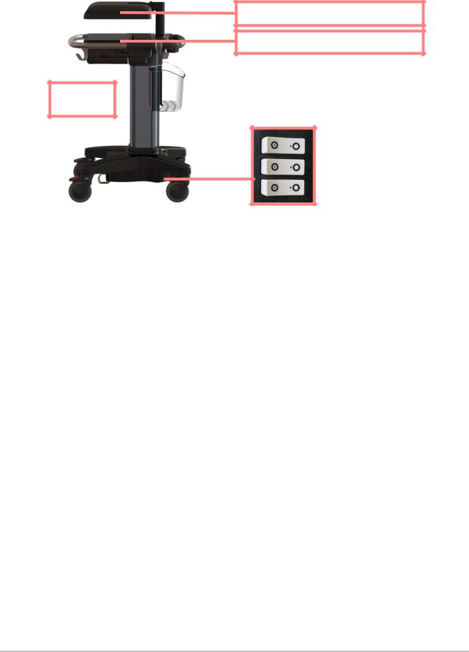
Stand collapsed (lowest height)  for transport.
Clinical Monitor display in the down (horizontal) transport position.
Touch Control Panel in the down (horizontal) transport position.
Access to the Stand battery switches can be gained by lifting the black plastic panel and pulling outward. This panel location is at the SPMU stand housing area near the left rear caster leg.
Battery
Switches
“•O”= OFF
Figure 3.1 Stand System Battery Switches & Transport Positioning
Electrical safety classification
Equipment safety
Please refer to the X-Porte Product Information and Safety Guide (P14646) for the complete information concerning all safety and standards applicable to the X-Porte Ultrasound System
DICOM standard
Please refer to the X-Porte Product Information and Safety Guide (P14646) for the complete information concerning the DICOM standard applicable to the X-Porte Ultrasound System
HIPAA standard
Please refer to the X-Porte Product Information and Safety Guide (P14646) for the complete information concerning HIPAA standard applicable to the X-Porte Ultrasound System
Transporting X-Porte Stand Systems
Please observe the prior Warnings and Cautions outlined in this chapter concerning the stand version system for transport and servicing. Lower (collapse) the stand to the lowest height position, fold to the horizontal position the Clinical Monitor display and touch Control Panel, and access the three battery switches and ensure that all switches are in the “•O” (OFF) position. Many government agencies require that no electronic equipment be shipped via air transport with live battery power attached to the equipment. Refer to Figure 3.1 on page 6 as to how to position the system stand and disconnect the battery power for transport and servicing.
Chapter 3: Safety |
7 |

8Chapter 3: Safety
Chapter 4: System Overview
About the System
The FUJIFILM SonoSite X-Porte high-resolution ultrasound system is a portable, full featured, general purpose, software controlled, diagnostic ultrasound system using all digital architecture. The system is used to acquire and display high-resolution, real-time ultrasound data in 2D, M Mode, Pulsed Wave (PW) Doppler, Continuous Wave (CW) Doppler, Color Power Doppler (CPD), and color Doppler (Color) or in a combination of these modes.
The system has an electrocardiography (ECG) display feature and supports a 3-lead ECG cable assembly to collect data for M Mode and Doppler measurements. The system provides measurement capabilities for anatomical structures and fetal biometry that provide information used for clinical diagnostic purposes. The system has a PW and CW Doppler audio output feature, cine review, image zoom, labeling, biopsy, measurements and calculations, image storage and review, printing, and recording capabilities.
The system includes optional Digital Imaging and Communications (DICOM) capabilities as well as general computer communication capabilities to provide the acceptance, transfer, display, storage, and digital processing of ultrasound images and loops. Security support is also provided to facilitate HIPAA compliance.
The system displays the current output level in terms of one of two bioeffects indices (“Mechanical Index [MI]” and “Thermal Index [TI]”) in accordance with the AIUM/NEMA Standard for Real Time Display of Thermal and Mechanical Acoustic Output Indices on Diagnostic Ultrasound Equipment.
Theory of Operation
The X-Porte ultrasound system has seven (7) major functional groups:
•Transducer
•Acquisition Subsystem
•Processing Subsystem
•Display Subsystem
•Control Subsystem
•User Interface Subsystem
•Power Subsystem
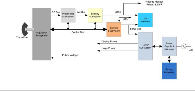
The following block diagram shows the relationship of the functional groups.
Chapter 4: System Overview |
9 |

Figure 4.1 Ultrasound System Functional Group
The Transducer elements convert the pulser voltage to acoustic energy during the transmit portion of the ultrasound acquisition cycle. The elements convert the acoustic echo to voltage in the receive portion of the acquisition. The voltage developed on the transducer elements is sensed by the acquisition subsystem. The system transducers have 64 to 256 elements.
The Acquisition Subsystem consists of the beamformer and interface to the transducer. The beamformer controls the timing of the transmit pulses to focus the acoustic beam. The beamformer amplifies the low-level received echos and controls the receive focusing. The system beamformer transmits on up to 128 elements and receives on 64 elements.
The Processing Subsystem includes capabilities for interfacing with the beamformer and performing high speed processing. The processing subsystem demodulates, filters, detects, and compresses the signal supplied by the beamformer into display information.
The DisplaySubsystemconverts the detected ultrasound data into picture elements (pixels). The software user interface graphics are combined with the ultrasound information and converted to a video stream. The external video port supports NTSC and PAL format.
The Control Subsystem consists of the central processing unit, program and video memory, permanent image storage and retrieval memory, external communication interface ports, and connection to the user interface keys. The control software includes the acoustic power and intensity software subsystem, power group monitors, and a beamformer monitor. This software guarantees a level of patient safety by ensuring the system is operating within acoustic power and intensity limits.
The User Interface Subsystem represents the software interface and form factor. The software interface is the interaction between the user and the screen layout components. The form factor is the type of physical buttons, location, and grouping of the buttons and the device size, shape, and weight. Dedicated controls are for high usage activities and grouped according to the user workflow.
The Power Subsystem provides the system power and protects the hardware from destructive and/or unsafe conditions by detecting failures in the system through hardware and software monitors. Detection of a fault results in disabling of the pulser supply, and signaling of an error to the Control Group. The power subsystem includes the batteries (quantity of three lithium-ion) and battery charging electronics.
Description of Operating Modes
2D Mode 2D mode is a two dimensional image of the amplitude of the echo signal. It is used for location and measurement of anatomical structures and for spatial orientation during operation of other modes. In 2D, a two-dimensional cross-section of a 3-dimensional soft tissue structure such as the heart is displayed in real time. Ultrasound echoes of different intensities are mapped to different gray scale or color values in the display.
The outline of the 2D cross-section may be a rectangle, parallelogram, trapezoid, sector, or a full circle, depending on the particular transducer used. 2D mode can be used in combination with any other modes.
M Mode M Mode is also known as “T-M mode” or “time-motion” mode. It is used primarily for cardiac measurements such as valve timing and septal wall thickness when accurate timing information is required.
Ultrasound echoes of different intensities are mapped to different gray scale values in a scrolling display. M Mode displays time motion information of the ultrasound data derived from a stationary beam. Depth is arranged along the vertical axis with time along the horizontal axis. M Mode can be used alone but is normally used in conjunction with a 2D image for spatial reference. The 2D image has a graphical line (M-line) superimposed on the 2D image indicating where the M Mode beam is located.
10 Chapter 4: System Overview

Color |
In color Doppler, a real-time, two-dimensional cross-section of blood flow is displayed. |
Doppler |
The 2D cross-section may be presented as a rectangle, parallelogram, trapezoid, |
(Color) |
sector, or a full circle, depending on the particular transducer used. |
|
The 2D cross-section is presented as a full color display, with various colors being used |
|
to represent the velocity, both positive and negative, of the blood flow echoes. Often, to |
|
provide spatial orientation, the full color blood flow cross-section is overlaid on top of |
|
the gray scale cross-section of soft tissue structure (2D echo). For each pixel in the |
|
overlay, the decision of whether to display VCD, gray scale (echo) information or a |
|
blended combination is based on the relative strength of echoes from the soft-tissue |
|
structures and from the red blood battery. |
|
A high pass filter (wall filter) is used to remove the signals from stationary or slowly |
|
moving structures. Tissue motion is discriminated from blood flow by assuming that |
|
blood is moving faster than the surrounding tissue, although additional parameters may |
|
also be used to enhance the discrimination. The remaining signal after wall filtering |
|
may be averaged over time (persistence) to present a steady state image of blood flow |
|
distribution. Variance information may also be displayed to provide information when |
|
large variance is observed in the velocity information. |
Color Power |
In CPD, a real-time two-dimensional cross-section of blood flow is displayed. The 2D |
Doppler |
cross-section may be presented as a rectangle, parallelogram, trapezoid, sector, or a |
(CPD) |
full circle, depending on the particular transducer used. |
|
The 2D cross-section is presented as a full color display, with various colors being used |
|
to represent the power in blood flow echoes. Often, to provide spatial orientation, the |
|
full color blood flow cross-section is overlaid on top of the gray scale cross-section of |
|
soft tissue structure (2D echo). For each pixel in the overlay, the decision of whether to |
|
display CPD, gray scale (echo) information or a blended combination is based on the |
|
relative strength of echoes from the soft-tissue structures and from the red blood |
|
battery. |
|
A high pass filter (wall filter) is used to remove the signals from stationary or slowly |
|
moving structures. Tissue motion is discriminated from blood flow by assuming that |
|
blood is moving faster than the surrounding tissue, although additional parameters may |
|
also be used to enhance the discrimination. The power in the remaining signal after |
|
wall filtering may be averaged over time (persistence) to present a steady state image |
|
of blood flow distribution. |
Continuous |
CW provides a real-time representation of blood flow and is displayed as a |
Wave (CW) |
velocity-versus-time sweeping output. Velocity (or frequency) is presented as the |
Doppler |
vertical axis with time along the horizontal axis. The magnitude of the detected signal is |
|
represented as different gray scale values. |
|
CW Doppler mode provides the clinician with the ability to obtain blood flow velocities |
|
focused about a user specified focal region. A continuous transmit waveform of |
|
ultrasound energy with a known frequency is transmitted and focused by the system; |
|
on the receive side, the transducer receive echoes are continuously amplified, focused |
|
about the focal region and converted to a base band quadrature signal. The signal is |
|
analyzed by a quadrature phase detector that establishes two receive channels to |
|
allow detection of flow direction. These two channels are then analyzed by a fast |
|
complex Fourier transform (FFT) circuit to establish the spectrum of frequencies |
|
present in the echoes. The data are displayed as spectrum frequencies with respect to |
|
time. |
|
CW can be used alone but is normally used in conjunction with a 2D image for spatial |
|
reference. The 2D image has a graphical line (D-line) superimposed on the 2D image |
|
indicating where the M-mode beam is located. |
Chapter 4: System Overview |
11 |

PulsedWave |
PW provides a real-time representation of blood flow and is displayed as a |
(PW) |
velocity-versus-time sweeping output. Velocity (or frequency) is presented as the |
Doppler |
vertical axis with time along the horizontal axis. The magnitude of the detected signal is |
|
represented as different gray scale values. The ultrasound data is derived from a single |
|
area, the sample volume, on a stationary beam. |
|
PW Doppler mode provides the clinician with the ability to obtain blood flow velocities |
|
about a spatial sample volume. A burst of ultrasound with a known spectrum is |
|
transmitted by the system; on the receive side, the transducer receive echoes are |
|
amplified and range gated at the appropriate depth. The signal is analyzed by a |
|
quadrature phase detector that establishes two receive channels to allow detection of |
|
flow direction. These two channels are then analyzed by a fast complex Fourier |
|
transform (FFT) circuit to establish the spectrum of frequencies present in the echoes. |
|
The data are displayed as spectrum frequencies with respect to time. |
|
PW can be used alone but is normally used in conjunction with a 2D image for spatial |
|
reference. The 2D image has a graphical line (D-line) superimposed on the 2D image |
|
indicating where the M-mode beam is located. The sample volume position (depth) and |
|
size are also indicated on the D-Line. |
Additional System Feature Performances
Broadband Imaging This ultrasound acquisition system uses high resolution broadband technology in the transmit pulsers, transducer, and receivers. The receive path can capture and process signals over a wide spectrum, from below 2.0 MHz to beyond 10 MHz. For each application, the transmit pulse is designed to produce an appropriate bandwidth. For example, in 2D grayscale imaging, a wide band pulse is used to support good axial resolution. For Doppler modes, a narrower band pulse is used, which improves the spectral resolution of the detected Doppler signal.
|
In addition to transmit pulse control, programmable digital signal processing is |
|
used in the receive path to further refine the bandwidth used to produce the |
|
final image. Digital filters are applied to the digitized received signal to limit and |
|
shape the spectral bandwidth used to generate the displayed output. |
Tissue Specific |
In this feature, parameters for signal and image processing are optimized to |
Imaging |
maximize the image quality or to obtain the best compromise of resolution and |
|
penetration for different specific clinical applications. These parameters |
|
include: the order of received filters, the bandwidth, the dynamic range, the |
|
compression curve, the gain setting and parameters for compounding |
|
frequency band, etc. For example, different system parameter setups are used |
|
for abdominal or peritoneal scanning. This feature is for ease of use for the |
|
operator by automatically setting up system control parameters rather than |
|
manually adjusting settings for best performance. |
Biopsy Guidance |
The system can display a pair of biopsy guidelines that represent the |
|
anticipated path of the biopsy needle. The image of an anatomical target, |
|
biopsy guidelines, a scan plane marker, and a biopsy needle are displayed to |
|
assist in guiding the biopsy needle to the target. The system also provides |
|
needle guidance for vascular access procedures. For additional information, |
|
see the biopsy user guides. |
Measurement and |
The system offers a variety of measurements and calculations, specific to |
Calculation |
exam type and transducer. A list of them, and author references, are in the |
Capabilities |
system user guide. Measurement accuracy is also discussed. |
12 Chapter 4: System Overview
Continuous Wave |
The system provides for audio output of the CW velocity information. This can |
Doppler Audio |
be presented as stereo information, with flow moving towards the transducer |
Output |
on one channel and flow away on the other, or as a mono output with the single |
|
audio output representing the summation of the flow directions. |
Pulsed Wave |
The system provides for audio output of the PW velocity information. This can |
Doppler Audio |
be presented as stereo information, with flow moving towards the transducer |
Output |
on one channel and flow away on the other, or as a mono output with the single |
|
audio output representing the summation of the flow directions. |
Electrocardiograph ECG is provided to measure the electrical signal generated by the heart. A (ECG) Display three lead interface: Right Arm (RA), Left Arm (LA) and Left Leg (LL), is
provided on the system.
The ECG signal is displayed as an amplitude-versus-time sweeping output. Amplitude is presented on the vertical axis with time along the horizontal axis.
Front End Overview
The Front End is designed to support various imaging modalities such as 2D, M-Mode, Spectral Doppler and Color Doppler. From the Front End's perspective, all modes can be grouped into a few basic types: Single mode, simultaneous modes and triggered modes. All these modes are built from similar, basic transmit and receive sequences controlled within the Front End. A generic top level block diagram of a typical Front End is shown below in Figure 4.2 on page 13
Transducer |
Receive Section |
|
|
T/R Sw |
|
|
|
|
A/D |
Delay |
X |
|
TGC Amplifier |
|
Weight |
Pulser |
Delay |
|
Beamformed |
|
Data |
||
|
Waveform |
|
|
T/R Sw |
|
|
|
|
A/D |
Delay |
X |
|
TGC Amplifier |
|
Weight |
Pulser |
Delay |
|
|
|
Waveform |
|
Control |
|
Transmit Section |
|
|
Figure 4.2 Generic Front End Block Diagram
The transmit section consists of a waveform generator, delay block, and high power high voltage driver to excite the transducer element. Multiple elements are driven with delays determined by the time of flight in the medium from the elements to the point in space where the beam is to be focused. The longer the time of flight is to the focal point the smaller the delay is for a given transmit element to allow all to arrive at the
Chapter 4: System Overview |
13 |

focal point at the same time. The number of elements driven is determined by element sensitivity off axis and depth of field considerations. The waveform is selected to drive the transducer at a certain center frequency, bandwidth, and power and is optimized for the given mode.
The receive section consists of a transmit/receive switch to protect the receiver from the transmit voltage, a variable gain receiver to amplify and condition the return echoes, an A/D to digitize the data, a delay block to focus the return signals and a weight block to scale the return echoes for each channel. All the signals are then summed together to generate the beam-formed receive data. The analog gain varies with depth to compensate for signal attenuation through the medium. The delays and weights are independent for each channel. The delay and weight for the receive channel can typically be changed dynamically to keep the receive beam in continuous focus. The delay is simply set by the time of flight in the medium from the point of interest to the element, which starts at skin-line and proceeds to the deepest depth of interest.
The control section drives the data to the various data path elements on a line by line basis, controls the timing of the transmit and receive sections and controls the tagged information and timing of the data to the rest of the system.
X-Porte Front End Board
The X-Porte ultrasound system can be divide into two board section groups: Front End and Back End. Below is the block diagram linking the necessary functional groups of an ultrasound system as they apply to the X-Porte system. Please refer to Figure 4.3 on page 14
Figure 4.3 X-Porte Front End Board Block Diagram
14 Chapter 4: System Overview

PW Doppler Processing
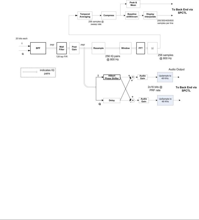
Doppler processing includes both audio processing which presents Doppler signal in the form of stereo audio and spectral processing which generates data for display of Doppler spectrum in the form of a scrolling spectrogram. Doppler power spectrum is estimated performing Discrete Fourier Transforms on short, overlapped segments of wall filtered Doppler signal. Doppler audio data is generated from wall filtered data by phase shifting the in-phase component. Refer to the PW Doppler Processing Function Block Diagram Figure 4.4 on page 15
Figure 4.4 PW Doppler Processing Function Block Diagram
Chapter 4: System Overview |
15 |
CW Doppler Processing
CW Doppler data will be presented to the signal processor as complex (I/Q) data from the analog front end of the external DSP. The 20-bit data will be presented as consecutive samples at a data rate varying from 1.5 kHz to 64 kHz for the complex pair. Most of CW processing is similar to that of PW except for the QBP function. In place of QBP will be a low pass decimating filter that operates on incoming I/Q data.
The Doppler Processing block must allow storage of 256 undetected I/Q pairs in to allow the system to measure and correct for phase mismatch. Measuring and correcting will need to be accomplished in system software. Refer to the CW Doppler Processing Function Block Diagram Figure 4.5 on page 16
Figure 4.5 CW Doppler Processing Function Block Diagram
16 Chapter 4: System Overview
Back End Overview
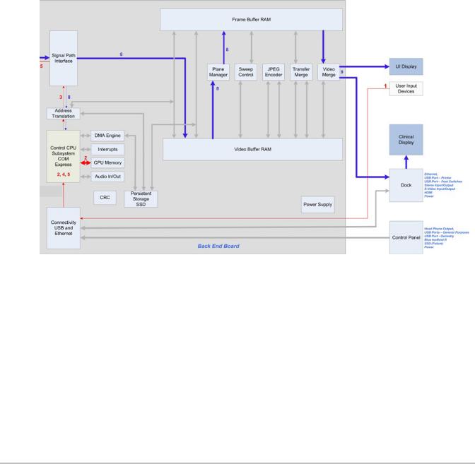
The Back End subsystem is responsible for the conversion of raw acquisition data into a raster image ready for display. The Back End subsystem also contains the video data path that supports generation of video comprising of the ultrasound image as well as graphics annotation. Video generation of both standard composite interlaced video and progressive scan video is supported. Most functionality is within the ASIC but the memory resources for acquisition memory, and display memory are found in external memory components. The conversion from PC type video to TV type video is also performed externally.
Control is received initially from the CPU to setup each functional block and afterward the hardware is completely data driven. This control takes the form of programming setup registers inside the blocks and setting up scan conversion tables. Each block provides temporary storage as required to buffer data and keep their respective processing pipeline full and operating. Also note that the block diagrams show only the data path, but each block is responsible for generating any necessary memory addresses for their respective input data stream.
The X-Porte Back End subsystem is shown in Figure 4.6 on page 17.
Figure 4.6 X-Porte System Back End Subsystem Block Diagram
The Back End Subsystem performs processing encompassing three main data domains, acquisition data, raster data, and video data. Support for acquisition data includes the input buffer, flash suppression, frame average, and external ACQ memory. Cine buffer management is performed by the acquisition controller. Conversion from acquisition data to raster data is performed by the graphics overlay, scan conversion system, sweeping system, and 3D system. Raster data is stored in an external DISPLAY memory. Also supporting raster operations is the graphics support block that provides acceleration hardware for pixel operations from the CPU and graphics overlay system. The progressive video path includes buffers, priority logic, and LUTs.
Chapter 4: System Overview |
17 |

Control Subsystem
The X-Porte Control Subsystem is shown in the figure below.
Control/Processor Section
Serial Port
HDA
SDVO 720P |
CH7308A |
LVDS (24 bit) |
|
10 |
|
|
|
LVDS (24 bit) |
|||
COMe Type |
|||
|
|
||
SATA 2
Processor
SATA Boot
Device
Connector
PCI Express
GPIO
Some GPIOs
tied to both
FPGA and
CPLD
Hirose: (Debug only)
10/100/1G Ethernet
I2C
Backlight enable and brightness
USB Host for Touch Screen
USB Host for Dock
PCI Express for Dock
SATA 2
Headphones
Speakers
Audio Codec/
Amp |
Line In |
S/PDIF
Control FPGA
Hard IP Block in FPGA
Soft IP Block in FPGA
Interrupts from the Front
End,and FPGA.
Program
JTAG |
Configuration |
|
|
|
|
Video Buffer Ram |
|||
|
FLASH/CPLD |
|
||
|
|
|
|
DDR3 1 GByte |
|
|
|
|
|
Switch |
Ethernet |
RJ45 |
|
10/100/1G |
|
|
Ethernet |
|
|
10/100/1G Ethernet |
|
Video out (LVDS) |
If M2/S2: Main Clinical display |
|
If POC: Touch Screen |
Serial Port
Headphones
Speakers
Audio Line In
GPIOs to Dock (TBD) |
|
||
|
HDMI/DVI |
|
|
24 bit video |
receiver |
HDMI in |
|
TP401A or |
|||
|
|
||
|
equivalent |
|
|
|
|
24 bit Video to |
|
|
|
VGA |
|
|
|
ADV7123 or |
|
S/PDIF |
|
Equivalent |
|
|
|
||
Display Control I/F |
|
HDMI/DVI |
Display Control I/F |
|
|
||||
|
|
|
|
transmitter |
|
|
|||
|
24 bit video |
|
AD9889B or |
|
|
|
|
|
|
|
|
|
|
equivalent |
|
|
|
|
|
|
|
|
|
|
|
Switch |
|
|
|
|
|
|
|
|
|
|
|
|
|
|
|
|
|
|
|
|
|
|
|
|
|
|
|
|
|
|
|
|
|
Dock Connector
Note:
HDMI with
Audio
Main Clinical display for POC. If M2/S2 to Dock for Aux Monitor with Audio
SATA2 |
|
SATA Connector |
|
|
FE I/F Connector |
Serial Lite (x4), WakeFromFE, FE_Detect |
|
|
|
||
|
|
|
Connector (Debug only)
JTAG
|
Mini PCIe |
PCI Express for WiFi |
(Debug Only) |
|
USB |
USB Host |
|
USB Module
WiFi
USB Type A (x3) USB Host x3
Figure 4.7 Control Subsystem Block Diagram
The core control subsystem contains the processor, the system bus, and the system memory resources of RAM and solid state hard drives. These two solid state hard drive devices are responsible for the system operating
system software, ultrasound program software, scanhead operation files, on-board training videos, and storage for patient data (patient demographic information, images, and video clips)
18 Chapter 4: System Overview
The main operational solid state storage drive is a mSATA form factor device totalling 16 GB of storage capacity. This device is responsible for handling the operational system software, the ultrasound program, and the on-board training videos.
A secondary solid state storage drive of 80 GB with an 1.8 inch form factor is used to handle the scanhead data files, other ultrasound system files, and 66 GB of storage capacity reserved for all patient data. It is with these new solid state devices, the X-Porte architecture is similar to our past products utilizing CF and SD storage cards, but with much improved data storage and throughput without the use of any mechanical hard drive devices.
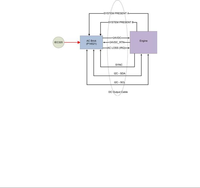
Power Supply and Control
The X-Porte ultrasound system utilizes one of two types of power supply arrangements depending on the X-Porte system version, which are Desktop or Stand. The Desktop system uses two separate external power supply (EPS) units. The 150 watt EPS supplies +24VDC to the main Ultrasound System Electronics (Engine) and a separate 65 watt EPS is utilized to supply +24VDC for the Clinical Display Monitor. No batteries can be utilized with this version of system. The electrical block diagram for the 150 watt EPS is shown below in Figure 4.8 on page 19
Figure 4.8 Desktop External Power Supply (EPS)
The Stand version X-Porte system utilizes a power supply/power control module mounted under the stand base. This System Power Management Unit (SPMU) supplies the +24VDC power to the Engine and Clinical Display Monitor. This SPMU is also the mounting point for the three lithium-ion batteries, charges the batteries, and is responsible for switching the system fromAC power to battery power when needed. Please refer to Figure 4.9 on page 20
Chapter 4: System Overview |
19 |
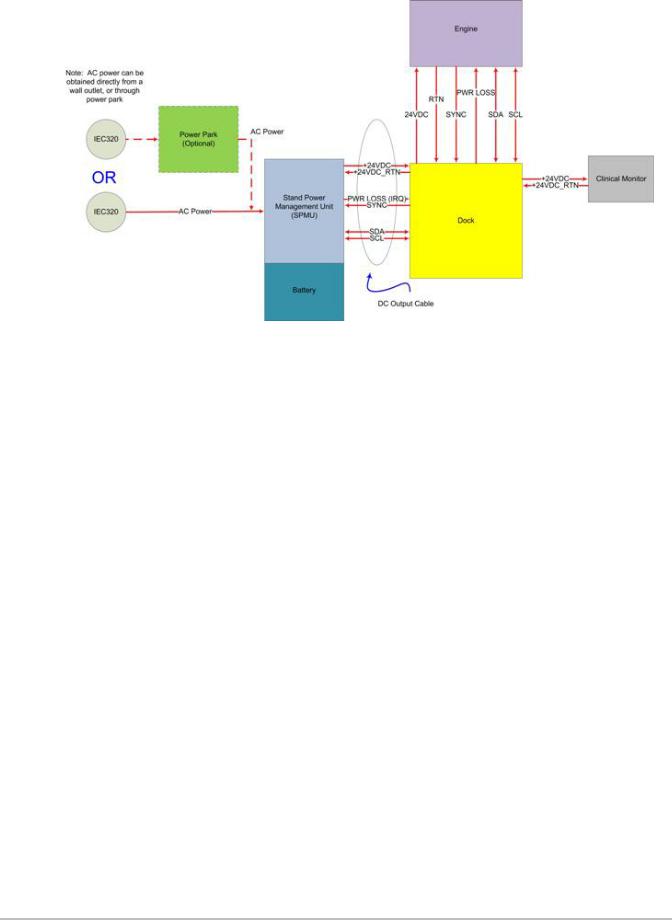
Figure 4.9 Stand Power Management Unit (SPMU)
ECG Module
The ECG module allows a representation of the heart electrical activity to be displayed in real time with ultrasound images acquired and displayed on the system video display.
The ECG module interfaces to the patient through three (3) ECG leads: Right Arm ECG lead (RA), Left Arm ECG lead (LA), and Left Leg ECG lead (LL). The ECG received signal from the ECG electrodes are isolated, amplified, and filtered by the ECG module before it is sent to the system for further processing and display.
The ECG module and cable are an integrated assembly. The module receives power from the system. Patient isolation is provided by the ECG module, allowing the connection and signals to the system to be system-ground referenced. The isolation between the patient and the system meets the requirements of IEC 601-1 for Type CF equipment.
The ECG function accepts input from an external serial A/D and performs gain, filter, and DC Offset functions. The resultant data is output at either the 200Hz sample rate or decimates the data by 2 or 4 and outputs the data into acquisition memory. The data is assumed to be signed. An interrupt is provided that will interrupt the processor after a set delay from the detected level and slope. A simple block diagram is shown below in Figure 4.10 on page 21
20 Chapter 4: System Overview
Loading...