


SUPER BRIGHT T-1 3/4 (5 mm)
LED LAMP - Water Clear
PACKAGE DIMENSIONS
|
0.200 (5.08) |
5° |
0.180 (4.57) |
|
|
0.350 (8.89) |
0.040 (1.02) |
0.330 (8.38) |
1.00 (25.4) MIN
0.023 |
(0.58) |
|
0.017 |
(0.43) |
0.050 (1.27) |
SQ. (2X) |
NOM |
|
0.100 (2.54) |
|
|
NOM |
|
|
FLAT DENOTES
CATHODE
Ø0.230 (5.84)
NOTES:
1.Dimensions for all drawings are in inches (mm).
2.Lead spacing is measured where the leads emerge from the package.
3.Protruded resin under the flange is 1.5 mm (0.059") max.
SUPER ORANGE |
MV871X |
MV8713 |
MV8714 |
MV8715 |
MV8716 |
FEATURES
• Popular T-1 3/4 package
• Super high brightness suitable for outdoor
applications
• Solid state reliability
• Water clear optics
• Standard 100 mil. lead spacing
DESCRIPTION
This T-1 3/4 super bright LED has a moderate viewing angle of 12° for concentrated light output. It is made with an AllnGaP LED that emits orange light at 620 nm. It is encapsulated in a water clear epoxy lens package.
ABSOLUTE MAXIMUM RATINGS (TA = 25°C unless otherwise specified)
|
Parameter |
Symbol |
Rating |
Unit |
|
|
|
|
|
|
|
|
Operating Temperature |
TOPR |
-40 to +100 |
°C |
|
|
Storage Temperature |
TSTG |
-40 to +100 |
°C |
|
|
Lead Soldering Time |
TSOL |
260 for 5 sec |
°C |
|
|
Continuous Forward Current |
IF |
40 |
mA |
|
|
Peak Forward Current |
IF |
160 |
mA |
|
|
(f = 1.0 KHz, Duty Factor = 1/10) |
|
|||
|
|
|
|
|
|
|
|
|
|
|
|
|
Reverse Voltage |
VR |
5 |
V |
|
|
Power Dissipation |
PD |
100 |
mW |
|
1 of 4 |
1/27/00 |
300028A |
SUPER BRIGHT T-1 3/4 (5 mm)
LED LAMP - Water Clear
|
|
|
|
SUPER ORANGE |
|
MV871X |
|
|
|
|
|
|
MV8713 MV8714 |
|
|
|
|
|
|
|
|
MV8715 MV8716 |
|
|
|
|
|
|
|
|
|
|
|
||
|
|
|
|
|
|
|
|
|
|
ELECTRICAL / OPTICAL CHARACTERISTICS (TA =25°C) |
|
|
|
|
|||
|
Part Number |
MV8713 |
MV8714 |
MV8715 |
MV8716 |
Condition |
|
|
|
|
|
|
|
|
|
|
|
|
Luminous Intensity (mcd) |
|
|
|
|
|
IF = 20 mA |
|
|
Minimum |
630 |
1000 |
1600 |
|
2500 |
|
|
|
Typical |
940 |
1500 |
2400 |
|
3500 |
|
|
|
|
|
|
|
|
|
|
|
|
Forward Voltage (V) |
|
|
|
|
|
IF = 20 mA |
|
|
Maximum |
2.8 |
2.8 |
2.8 |
|
2.8 |
|
|
|
Typical |
2.1 |
2.1 |
2.1 |
|
2.1 |
|
|
|
|
|
|
|
|
|
|
|
|
Wavelength (nm) |
|
|
|
|
|
IF = 20 mA |
|
|
Peak |
620 |
620 |
620 |
|
620 |
|
|
|
Dominant |
615 |
615 |
615 |
|
615 |
|
|
|
|
|
|
|
|
|
|
|
|
Spectral Line Half Width (nm) |
20 |
20 |
20 |
|
20 |
IF = 20 mA |
|
|
Viewing Angle (°) |
12 |
12 |
12 |
|
12 |
IF = 20 mA |
|
TYPICAL PERFORMANCE CURVES
|
100 |
|
|
|
|
|
90 |
|
|
|
|
(mA) |
80 |
|
|
|
|
70 |
|
|
|
|
|
CURRENT |
60 |
|
|
|
|
FORWARD- |
50 |
|
|
|
|
40 |
|
|
|
|
|
|
30 |
|
|
|
|
F |
20 |
|
|
|
|
|
|
|
|
||
I |
|
|
|
|
|
|
10 |
|
|
|
|
|
0 |
|
|
|
|
|
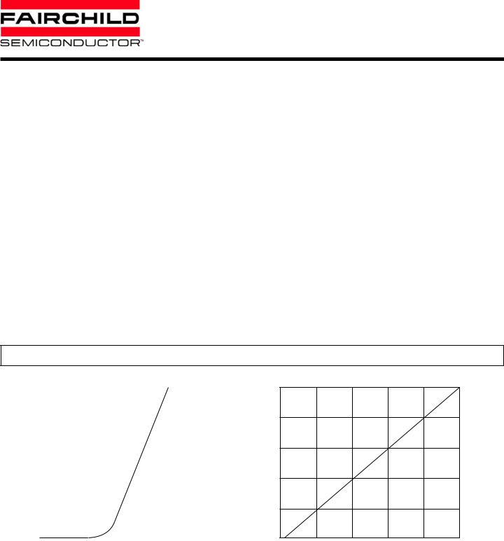
1.0 |
1.5 |
2.0 |
2.5 |
3.0 |
VF - FORWARD VOLTAGE (V)
Fig. 1 Forward Current vs. Forward Voltage
INTENSITY |
|
2.5 |
mA)20 |
2.0 |
|
|
|
|
RELATIVELUMNOUS |
(NORMALIZEDAT |
1.5 |
0.5 |
||
|
|
1.0 |
|
|
0.0 |
0 |
10 |
20 |
30 |
40 |
50 |
IF - DC FORWARD CURRENT (mA)
Fig. 2 Relative Luminous Intensity vs. DC Forward Current
2 of 4 |
1/27/00 |
300028A |
 Loading...