


EN BUILT-IN HOBS
SP PLACAS DE ENCASTRE
PT CHAPAS DE FOGAO
FR TABLES ENCASTRABLES
DE EINBAU-GASKOCHPLATTE
6CFI-5GL
6CFI-5GLST
6CFI-4GLS
6CFI-4GLSB
6CFIE-4GLS

Dear Sirs and Madams,
You have purchased a gas hob designed to be fitted in a kitchen worktop.
Thanks to its state-of-the art technological and aesthetic solutions the gas hob perfectly matches any interior allowing the user to arrange the kitchen room according to his or her needs and preferences.
This hob is not equipped with controls. It is designed to work together with an appropriate control panel or oven manufactured by our company.
The hob features gas burners and ignitors switched on by gas tap knobs.
The burners ensure complete stability of the flame, which prevents it from going out even when it is small.
The hob is also equipped with taps with flame failure device which cuts off gas supply to each burner when the flame has gone out eg as a result of accidental spillage or draught.
The glass surface of the hob is very attractive and easy to maintain.
Before the first use please read this instruction manual carefully as it includes tips and guidelines concerning the correct use of the appliance.
We hope you will be satisfied with our product.
FAGOR
EN |
1 |
1 |
GENERAL INFORMATION.............................................................................. |
3 |
|
|
1.1 |
PURPOSE OF THE APPLIANCE.............................................................. |
3 |
|
1.2 |
TECHNICAL DATA.................................................................................... |
3 |
|
1.3 |
MODELS OF GAS HOBS.......................................................................... |
4 |
|
1.4 |
SAFETY GUIDELINES .............................................................................. |
4 |
2 |
INSTALATION ................................................................................................. |
5 |
|
|
2.1 |
GENERAL TIPS......................................................................................... |
5 |
|
2.2 |
INSTALLATION OF THE GAS HOB ......................................................... |
6 |
|
2.3 |
CONNECTING THE HOB TO GAS SUPPLY............................................ |
7 |
3 |
THE USE OF THE BURNERS ....................................................................... |
11 |
|
|
3.1 |
OPERATION PRINCIPLES ..................................................................... |
11 |
|
3.2 |
CHOICE OF UTENSILS........................................................................... |
12 |
4 |
CLEANING AND MAINTENANCE ................................................................ |
13 |
|
|
4.1 |
GENERAL INSTRUCTIONS.................................................................... |
13 |
|
4.2 |
CLEANING THE BURNERS.................................................................... |
14 |
5 |
WHAT TO DO IF THE HOB MALFUNCTIONS ............................................. |
15 |
|
6 |
ENVIRONMENT PROTECTION .................................................................... |
17 |
|
Note:
Before using the appliance, please read this instruction manual carefully.
The appliance should be installed after 8 hours of seasoning in the kitchen room.
The gas hob is manufactured in class I of the security against electric shock and must be connected to the installation with working external earth circuit.
The hob should be connected to the gas system only by a properly certified fitter of gas appliances, which should be confirmed on the product’s warranty card. The lack of such confirmation will render the warranty null and void!
Prior to installation, ensure that the type of gas your are supplied with is compatible with the type of gas the hob is adjusted to. Information about the required type of gas is stated on the rating plate of the appliance.
The appliance should be installed and used in a well-ventilated room. Keep ventilation grates always open or install a forced ventilation system (a cooker hood).
No amateur repairs of the appliance are permitted on pain of losing the warranty rights.
In case of any problems with the appliance contact an authorised servicing company idicated by the appliance manufacturer.
2 |
EN |
1 GENERAL INFORMATION
1.1 PURPOSE OF THE APPLIANCE
Gas hobs are equipped with an integrated control system and are designed to be fitted in a kitchen worktop. They are designed for the preparation of meals only in a household. They must not be used for other purposes!
1.2 TECHNICAL DATA
|
|
|
|
|
|
|
|
|
|
|
Table 1 |
|
|
|
|
|
|
|
|
Type |
|
|
|
|
|
|
|
|
|
|
|
|
|
|
|
|
||
Characteristics |
|
|
|
|
|
|
|
|
|
|||
6CFI- |
6CFI- |
6CFI- |
6CFI- |
|
6CFI- |
6CFI- |
6CFIE- |
|
||||
|
|
|
|
5GL BUT |
5GLST |
5GLST |
4GLS |
|
4GLS |
4GLSB |
4GLS |
|
|
|
|
|
|
BUT |
NAT |
BUT |
|
NAT |
NAT |
NAT |
|
Hob's |
|
width |
700 |
700 |
700 |
594 |
|
594 |
594 |
594 |
|
|
|
|
|
|
|
|
|
|
|
|
|
||
|
|
|
|
|
|
|
|
|
|
|
||
overall |
|
depth |
575 |
575 |
575 |
520 |
|
520 |
520 |
520 |
|
|
dimensions |
|
|
|
|
|
|
|
|
|
|
|
|
[ mm ] |
|
height |
48 |
48 |
48 |
41 |
|
41 |
41 |
41 |
|
|
|
|
|
|
|
||||||||
|
|
|
|
|
|
|
|
|
|
|
|
|
Supply voltage |
|
|
1N ~ 230V 50Hz |
|
|
|
|
|||||
|
|
|
|
|
|
|
|
|
|
|
|
|
|
|
small 45 mm /1,0 |
1 |
1 |
1 |
1 |
|
1 |
1 |
1 |
|
|
|
|
kW |
|
|
|
|
|
|
|
|
|
|
Number |
|
medium 65 mm / |
2 |
2 |
2 |
2 |
|
2 |
2 |
2 |
|
|
of |
|
1,75 kW |
|
|
|
|
|
|
|
|
|
|
gasburne |
|
large 91 mm / 3,0 |
1 |
1 |
1 |
1 |
|
1 |
1 |
1 |
|
|
rs [units] |
|
|
|
|||||||||
|
kW |
|
|
|||||||||
|
|
|
|
|
|
|
|
|
|
|
||
|
|
triple crown burner |
1 |
1 |
1 |
— |
|
— |
— |
— |
|
|
|
|
125 mm / 3,6 kW |
|
|
||||||||
|
|
|
|
|
|
|
|
|
|
|
||
Knob-controlled spark ignitors |
• |
• |
• |
• |
|
• |
• |
• |
|
|||
|
|
|
|
|
|
|
|
|
|
|||
Flame failure device |
— |
• |
• |
• |
|
• |
• |
• |
|
|||
|
|
|
|
|
|
|||||||
|
|
|
|
|
|
|
|
|
|
|
|
|
Hob surface |
|
|
Glass |
Glass |
Glass |
Glass |
|
Glass |
Glass |
Glass |
|
|
|
|
|
|
black |
black |
black |
black |
|
black |
white |
black |
|
The hobs can be supplied with the following types of gas:
–natural gas 2H – (G20 20 mbar)
–LPG G30 29/37 mbar
Table 2
Type of gas |
Small burner |
Medium burner |
Large burner |
Three crown |
|
burner |
|||||
|
|
|
|
||
|
|
|
|
|
|
2H–(G20 20 mbar) |
X072 |
Z097 |
Y118 |
T135 |
|
|
|||||
|
|
|
|
|
|
LPG G30 29/37 |
050 |
065 |
085 |
095 |
|
mbar |
|||||
|
|
|
|
EN |
3 |
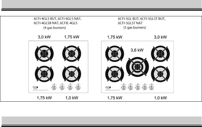
1.3 MODELS OF GAS HOBS
Fig.1
1.4 SAFETY GUIDELINES
The appliance should be operated by adults only; do not allow children to play nearor fiddle with the hob.
The appliance should be installed in compliance with the relevant laws in force and with the instructions contained in this manual. Do not install the appliance near flammable materials such as curtains, towels etc.
After the appliance is switched off, the ovens, electric plate, pan supports and pans with food remain hot for quite some time. Please pay special attention to children and do not allow them to come near the hob or touch the pans placed on it.
Ensure that the cables of other household appliances used near the working appliance are far from hot burners and electric plate.
Always use protective gloves when removing items from the hob.
Do not place dented or unstable pans on pan supports as they may topple over and flood the burners or plate.
Never leave the appliance with lit burners unattended, particularly when frying, as overheated fat may catch fire
Before removing the pans from the burners reduce the flame or switch it off completely.
Never use the appliance as a room heater.
In the event of the escape of gas:
–immediately close the valve on the gas supply system or cylinder,
–ventilate the room thoroughly,
–call gas emergency service.
In the meantime DO NOT!
–light matches, smoke cigarettes,
–turn on or off electric appliances (radio, doorbell, light switch) or mechanic appliances generating sparks
If the gas escaping from a leaky gas cylinder valve catches fire
–place a wet blanket on the cylinder to cool the cylinder down,
–close the cylinder valve.
4 |
EN |
DAMAGED CYLINDER MUST NOT BE USED !!
The failure should be reported to an authorised servicing company
DO NOT:
–place a large pan on two burners,
–use the hob in a room without effective ventilation,
–make any unauthorised adjustments of the hob to a different type of gas orchanges in the appliance’s gas and electric system; any modifications of the appliance cause danger to the user,
–make any unauthorised repairs;
–use the appliance with a damaged cable or plug,
–allow young children and people who have not read this manual to use the hob.
The manufacturer disclaims all liability for any injury or damage resulting from the improper operation of the appliance or its improper use or actions violat-ing the instructions of this manual.
2 INSTALATION
2.1 GENERAL TIPS
The manufacturer is not liable for damages resulting from non-compliance with standards and regulations in force and from the installation of the hob by an unauthorised person.
1.The appliance should be installed in a kitchen room that meets the following requirements:
–appropriate size ensuring that the maximum heat output from the installed gas appliances does not exceed 930 W/m3,
–a minimum height of 2.2 m,–ventilation system in good working order (ensuring that the air is exchanged at least 1.5 times per hour),
–ensured supply of air (if there is no window) through holes made in external walls with the area of at least 0.016 m2,
–ensured removal of fumes eg through a working chimney duct with a minimum side of 0.14 m.
2.In order to limit the negative influence of draughts on the operation of burners, do not install the hob on a window-door axis.
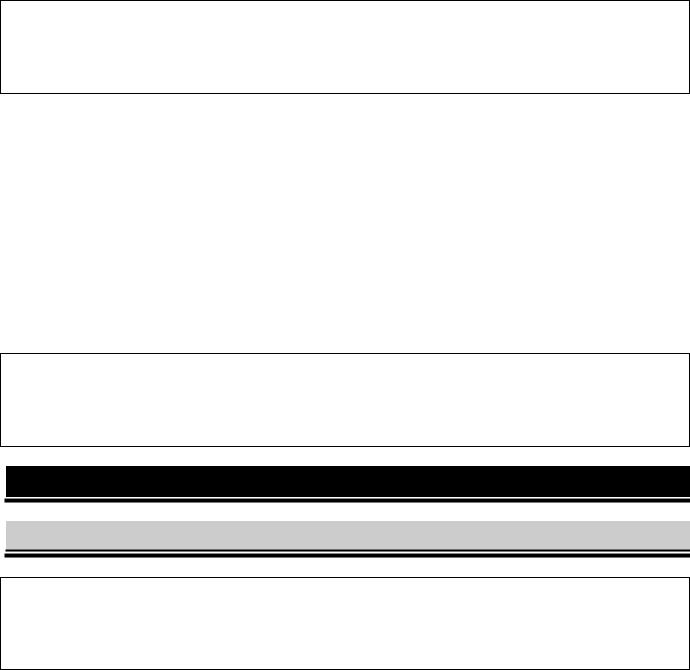
3.The appliance should be installed in a kitchen worktop not higher than 850 mm. The room wall adjacent to the hob should be made of non-flammable materials (fig. 2).
EN |
5 |
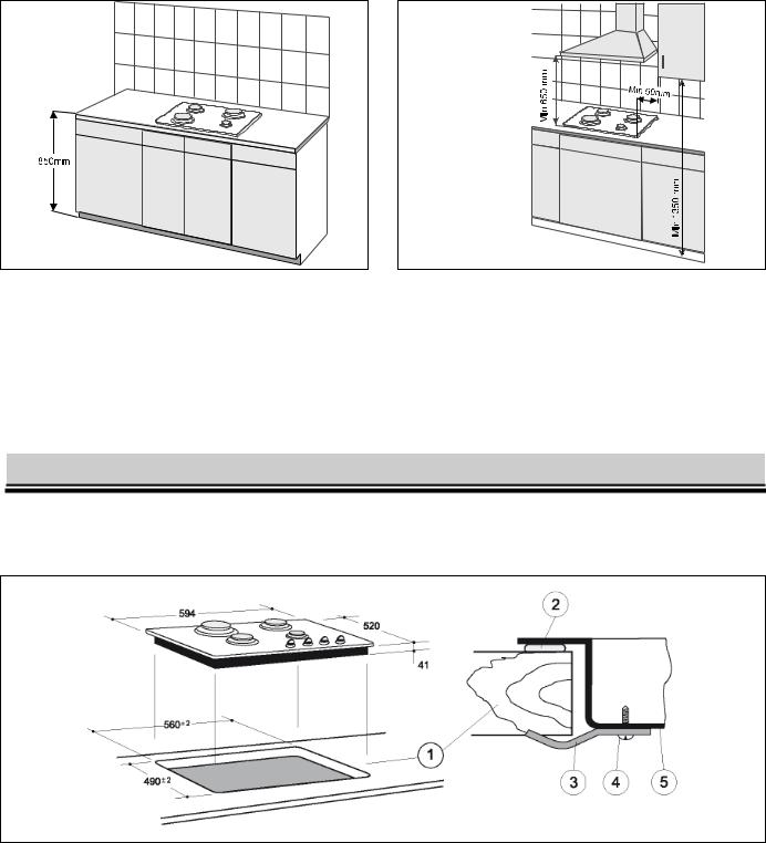
Fig.2 |
Fig.3 |
4.There should be an open space above the hob to allow kitchen odours to disperse. Installation of a cooker hood is recommended to either absorb or extract the odours.The distance between the hob and the hood should not be shorter than 650 mm (fig.3).
5. .Do not fit kitchen cabinets directly over the hob. The distance between the hob's side edges and the side edges of hanging cabinets should not be shorter than 50 mm (fig.3)
2.2INSTALLATION OF THE GAS HOB
1.Before the installation, please check the measures of the hob and the opening in the worktop where the hob is going to be installed.
Fig.4
2.Cut out a rectangular 490 x 560 mm hole in the worktop 1 (fig. 4).
3.Remove the backing paper from the provided sealing gasket.
4.Place the hob face down and affix the sealing gasket 2 all around the hob (fig. 4 and 5)
5.After affixing the gasket place the hob in the cavity in the worktop 1 and press down tightly so that sealing joint is perfectly closed
6.Fix the hob underneath to the worktop 1 with clamps 3 and screws 4 supplied in the accessory bag
7.Shelf "A" (fig. 6) should be installed under the worktop to protect the user from accidentally touching the hot hob from beneath. The shelf should be fitted after installing
the hob in the worktop.
6 |
EN |
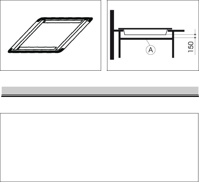
Fig.5 |
Fig.6 |
2.3 CONNECTING THE HOB TO GAS SUPPLY
Having installed the hob in the worktop, connect the appliance to internal gas supply system.
Note:
1.The connection of the hob to the gas supply system should be made in accordance with the regulations in force.
2.All activities involved in connecting the hob to the gas supply system, adjusting the taps and replacing nozzles should only be performed by a properly certified person
3.Before beginning the connection operation make sure that the gas valve is closed!
4.Incorrect connection and tension of the system may cause malfunction or even damage of the hob or gas supply system.
5.The manufacturer disclaims all liability for any
The gas hob is equipped with 1/2" connector pipe. Gas supply system should be connected to the pipe with appropriate fittings.
CONNECTING THE HOB TO NATURAL GAS SUPPLY
When connecting the hob to natural gas supply use an elbow with gasket and seal the taper thread (at the outlet) with Teflon band. The hob may be connected to the internal supply system with a rigid connection or a flexible metal tube. The connection method is shown in fig. 7.
EN |
7 |
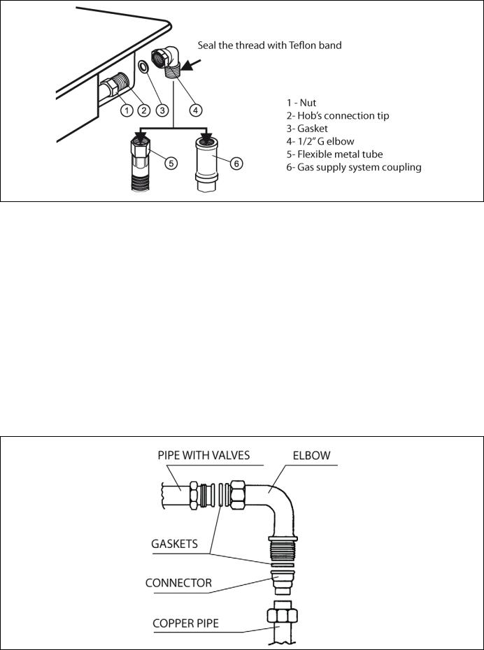
Fig. 7
CONNECTING THE HOB TO AN LPG CYLINDER
Do not install the appliance in the basement or in any other room whose floor is below the ground level as LPG is heavier than air and accumulates at the floor level.
The cylinder should be located in an easily accessible place, positioned vertically and secured against falling over.
When connecting the appliance to the cylinder use a flexible tube.
To connect the appliance use the LPG tip with a gasket as shown in fig. 8.
Each time after connecting the hob to LPG cylinder check the soundness on high pressure side, check the cylinder valve for soundness and the connection of regulator with the cylinder and its operation.
The soundness of all connections and the cylinder valve maybe pre-checked by applying soap solution on the said points with the normal working pres-sure. Appearing bubbles signal the escape of gas.
Fig.8
8 |
EN |

Note:
1.Under no circumstances can the gas soundness be checked by means of a naked flame (e.g. with a match or candle). Danger of explosion!
2.Regularly, every six months, check the condition of the tube and soundness of its connection to the end elements.
REPLACING THE NOZZLES
Note:
1.Before replacing the nozzles and adjusting gas taps remove the cable plugfrom the mains supply .
2.When adjusting the taps do not unscrew the needle completely.
The hob is adjusted to the type of gas and pressure stated on the appliance's rating plate. In the event of a change of the type of gas replace the nozzles and adjust the taps.
Before beginning these activities you must:
–shut down the cock shutting off the gas supply system or cylinder from the hob,-shut down all the taps in the hob,
–disconnect the hob from the mains.
Then:
–remove the burners' lids and rings,
–remove the nozzles with socket wrench no. 7 and replace them with new ones in accordance with table2,
–put burners' rings and lids back,-
–adjust the taps and check the connections for soundness
Fig.8
ADJUSTING THE TAPS
The adjustment of a gas tap consists in setting the burner flame in the simmering position. To adjust the taps remove all the knobs and control panel.
Then:
–open the gas flow with a knob and light the adjusted burner,
–set the knob in the simmering position  . and then, without changing that position, remove it from the tap's mandrel
–put a screwdriver in opening 'A" or mandrel opening "B" (depending on the type of the tap fig. 10) and turn it, observing the flame, to achieve such a size of the flame that will prevent it from being extinguished in a slight draught or during the operation of quick
switching from the full  to the simmering position
  . of the flame and back; the adjustment is correct when the core of the flame is cone-shaped in green and blue colour and is ca. 2 - 4mm tall,
EN |
9 |
–if there are perceptible changes of gas pressure in the gas supply system, the simmering flame should be set at the low pressure in the system to prevent the burner from extinguishing during normal use.
–after adjusting the taps put the knob back in its position and turn off the flame.
Fig. 10
CONNECTING THE HOB TO THE MAINS
The appliance is supplied with the mains cable without a plug.
Note:
1.The plug should be connected to the mains cable only by a properly certified installerelectrician.
2.The mains socket should be easily accessible to the user.
3.Please make sure that feed cable does not touch hot burners when the hob is working.
The hob is adjusted to alternating cur-rent 230V, 50Hz, and should be connected to the mains socket equipped with properly connected ground contact.
Connecting the hob to a socket without the ground contact causes a danger of electric shock in the even of a failure of the hob's electric system
Fig.11
10 |
EN |
 Loading...