


 Loading...
SERVICE MANUAL
Color Inkjet Printer
EPSON Stylus Photo R240/R245/R250
EPSON ME PHOTO 20
SEIJ05011
|
PRECAUTIONS |
Precautionary notations throughout the text are categorized relative to 1)Personal injury and 2) damage to equipment. |
|
DANGER |
Signals a precaution which, if ignored, could result in serious or fatal personal injury. Great caution should be exercised in performing |
|
procedures preceded by DANGER Headings. |
WARNING |
Signals a precaution which, if ignored, could result in damage to equipment. |
The precautionary measures itemized below should always be observed when performing repair/maintenance procedures.
DANGER
1.ALWAYS DISCONNECT THE PRODUCT FROM THE POWER SOURCE AND PERIPHERAL DEVICES PERFORMING ANY MAINTENANCE OR REPAIR PROCEDURES.
2.NO WORK SHOULD BE PERFORMED ON THE UNIT BY PERSONS UNFAMILIAR WITH BASIC SAFETY MEASURES AS DICTATED FOR ALL ELECTRONICS TECHNICIANS IN THEIR LINE OF WORK.
3.WHEN PERFORMING TESTING AS DICTATED WITHIN THIS MANUAL, DO NOT CONNECT THE UNIT TO A POWER SOURCE UNTIL INSTRUCTED TO DO SO. WHEN THE POWER SUPPLY CABLE MUST BE CONNECTED, USE EXTREME CAUTION IN WORKING ON POWER SUPPLY AND OTHER ELECTRONIC COMPONENTS.
4.WHEN DISASSEMBLING OR ASSEMBLING A PRODUCT, MAKE SURE TO WEAR GLOVES TO AVOID INJURIER FROM METAL PARTS WITH SHARP EDGES.
WARNING
1.REPAIRS ON EPSON PRODUCT SHOULD BE PERFORMED ONLY BY AN EPSON CERTIFIED REPAIR TECHNICIAN.
2.MAKE CERTAIN THAT THE SOURCE VOLTAGES IS THE SAME AS THE RATED VOLTAGE, LISTED ON THE SERIAL NUMBER/RATING PLATE. IF THE EPSON PRODUCT HAS A PRIMARY AC RATING DIFFERENT FROM AVAILABLE POWER SOURCE, DO NOT CONNECT IT TO THE POWER SOURCE.
3.ALWAYS VERIFY THAT THE EPSON PRODUCT HAS BEEN DISCONNECTED FROM THE POWER SOURCE BEFORE REMOVING OR REPLACING PRINTED CIRCUIT BOARDS AND/OR INDIVIDUAL CHIPS.
4.IN ORDER TO PROTECT SENSITIVE MICROPROCESSORS AND CIRCUITRY, USE STATIC DISCHARGE EQUIPMENT, SUCH AS ANTI-STATIC WRIST STRAPS, WHEN ACCESSING INTERNAL COMPONENTS.
5.REPLACE MALFUNCTIONING COMPONENTS ONLY WITH THOSE COMPONENTS BY THE MANUFACTURE; INTRODUCTION OF SECONDSOURCE ICs OR OTHER NON-APPROVED COMPONENTS MAY DAMAGE THE PRODUCT AND VOID ANY APPLICABLE EPSON WARRANTY.
6.WHEN USING COMPRESSED AIR PRODUCTS; SUCH AS AIR DUSTER, FOR CLEANING DURING REPAIR AND MAINTENANCE, THE USE OF SUCH PRODUCTS CONTAINING FLAMMABLE GAS IS PROHIBITED.

About This Manual
This manual describes basic functions, theory of electrical and mechanical operations, maintenance and repair procedures of the printer. The instructions and procedures included herein are intended for the experienced repair technicians, and attention should be given to the precautions on the preceding page.
Manual Configuration
This manual consists of six chapters and Appendix.
CHAPTER 1. PRODUCT DESCRIPTIONS
Provides a general overview and specifications of the product.
CHAPTER 2. OPERATING PRINCIPLES
Describes the theory of electrical and mechanical operations of the product.
CHAPTER 3. TROUBLESHOOTING
Describes the step-by-step procedures for the troubleshooting.
CHAPTER 4. DISASSEMBLY/ASSEMBLY
Describes the step-by-step procedures for disassembling and assembling the product.
CHAPTER 5. ADJUSTMENT
Provides Epson-approved methods for adjustment.
CHAPTER 6. MAINTENANCE
Provides preventive maintenance procedures and the lists of Epson-approved lubricants and adhesives required for servicing the product.
CHAPTER 7. APPENDIX
Provides the following additional information for reference:
•Connector Summary
•Exploded Diagram
•Electrical Circuits
Symbols Used in this Manual
Various symbols are used throughout this manual either to provide additional information on a specific topic or to warn of possible danger present during a procedure or an action. Be aware of all symbols when they are used, and always read NOTE, CAUTION, or WARNING messages.
ADJUSTMENT REQUIRED
CAUTION
CHECK
POINT
Indicates an operating or maintenance procedure, practice or condition that, if not strictly observed, could result in injury or loss of life.
Indicates an operating or maintenance procedure, practice, or condition that, if not strictly observed, could result in damage to, or destruction of, equipment.
May indicate an operating or maintenance procedure, practice or condition that is necessary to accomplish a task efficiently. It may also provide additional information that is related to a specific subject, or comment on the results achieved through a previous action.
WARNING |
Indicates an operating or maintenance procedure, practice or |
|
condition that, if not strictly observed, could result in injury or loss |
|
of life. |
Indicates that a particular task must be carried out according to a certain standard after disassembly and before re-assembly, otherwise the quality of the components in question may be adversely affected.

Revision Status
Revision |
Date |
Item |
Description |
A |
October 7, 2005 |
--- |
First Release |
|
|
|
|
B |
March 10, 2006 |
5.1.2 Adjustments Required After Part |
PW Sensor Adjustment (PW Deterioration Adjustment) added after Main |
|
|
Replacement (p.129) |
Board Replacement(Read OK) |
|
|
|
|
C |
October 6, 2006 |
All |
EPSON ME PHOTO 20 is added. |
|
|
|
|
|
|
1.2.1.3 Paper Support (p.11) |
Table 1-3 “Exclusive Papers” is modified. |
|
|
|
|
|
|
1.2.1.5 Ink Cartridge Specification (p.15) |
EPSON ME PHOTO 20 is added. |
|
|
|
|
|
|
1.6.3 Control Panel Appearance (p.31) |
EPSON ME PHOTO 20 is added. |
|
|
|
|
|
|
5.1.2 Adjustments Required After Part |
Error correction |
|
|
Replacement (p.129) |
|
|
|
|
|

EPSON Stylus Photo R240/R245/R250/ME PHOTO 20 |
Revision C |
Contents
Chapter1 |
PRODUCT DESCRIPTION |
|
|
1.4.3 Layout and Paper Type, Paper Size ......................................................... |
23 |
|||||
|
|
|
|
|
|
1.4.4 |
Trimming Function |
23 |
||
1.1 |
Overview |
10 |
|
|||||||
|
1.4.5 Assignment Rules for Photo Frame Numbers and Rotation |
24 |
||||||||
|
1.1.1 |
Features |
10 |
|
||||||
|
|
1.4.6 |
Layout Drawings |
25 |
||||||
1.2 |
Specifications |
11 |
|
|||||||
|
1.4.6.1 |
Border free ........................................................................................ |
25 |
|||||||
|
1.2.1 |
Printer specifications................................................................................ |
11 |
|
1.4.6.2 |
1-up with borders .............................................................................. |
25 |
|||
|
1.2.1.1 |
Physical Specification ....................................................................... |
11 |
|
1.4.6.3 |
20-up ................................................................................................. |
26 |
|||
|
1.2.1.2 |
Printing Specification........................................................................ |
11 |
|
1.4.6.4 |
30-up ................................................................................................. |
26 |
|||
|
1.2.1.3 |
Paper Support.................................................................................... |
11 |
|
1.4.6.5 |
80-up ................................................................................................. |
27 |
|||
|
1.2.1.4 |
Printing Area ..................................................................................... |
13 |
|
1.4.7 Relation between Paper Type and Quality............................................... |
27 |
||||
|
1.2.1.5 |
Ink Cartridge Specification ............................................................... |
15 |
1.5 |
USB Direct-Print/PictBridge Functions |
28 |
||||
|
1.2.1.6 |
Electric Specification |
15 |
|||||||
|
|
1.5.1 |
Supported Device |
28 |
||||||
|
1.2.1.7 |
Environmental Performance |
16 |
|
||||||
|
|
1.5.2 Functions Available from DSC |
28 |
|||||||
|
1.2.1.8 |
Durability |
16 |
|
||||||
|
|
1.5.3 |
Operation |
28 |
||||||
|
1.2.1.9 |
Safety Standards: EMC |
16 |
|
||||||
|
|
1.5.3.1 |
Preparation |
28 |
||||||
|
1.2.1.10 CE Marking |
16 |
|
|||||||
|
|
1.5.3.2 |
Standard Operations |
28 |
||||||
1.3 |
Interface |
|
17 |
|
||||||
............................................................................................................ |
|
1.5.3.3 Display when DSC is Connected...................................................... |
29 |
|||||||
|
1.3.1 |
USB Interface........................................................................................... |
17 |
|
1.5.3.4 |
Cancel Print....................................................................................... |
29 |
|||
|
1.3.2 |
Standard Card Slots.................................................................................. |
18 |
|
1.5.3.5 Operation when the Printing is Completed....................................... |
29 |
||||
|
1.3.2.1 |
Memory card ..................................................................................... |
18 |
|
1.5.3.6 |
Exclusive Control Specifications for Paper Type, Size, and Layout 29 |
||||
|
1.3.2.2 Supported power supply voltage....................................................... |
18 |
|
1.5.3.7 Camera direct error executing other processing (error).................... |
29 |
|||||
|
1.3.2.3 |
Multi-slot operations......................................................................... |
19 |
1.6 |
Control Panel |
30 |
||||
1.4 |
Memory Card Print |
20 |
||||||||
|
1.6.1 |
Buttons ..................................................................................................... |
30 |
|||||||
|
1.4.1 |
Basic Specifications ................................................................................. |
20 |
|
1.6.2 |
Indicators.................................................................................................. |
30 |
|||
|
1.4.1.1 |
File system ........................................................................................ |
20 |
|
1.6.3 |
Control Panel Appearance ....................................................................... |
31 |
|||
|
1.4.1.2 |
Media format..................................................................................... |
20 |
|
1.6.4 The method of changing mode................................................................. |
32 |
||||
|
1.4.1.3 |
File formats ....................................................................................... |
20 |
|
1.6.5 |
Operations ................................................................................................ |
33 |
|||
|
1.4.1.4 |
Valid image size................................................................................ |
20 |
|
1.6.5.1 Memory card mode/Setup mode/DSC direct mode.......................... |
33 |
||||
|
1.4.1.5 |
Maximum number of photo data files............................................... |
21 |
|
1.6.5.2 |
Memory Card Insertion/Ejection ...................................................... |
35 |
|||
|
1.4.1.6 |
Thumbnail image data....................................................................... |
21 |
|
1.6.5.3 |
Connection/Removal of DSC ........................................................... |
35 |
|||
|
1.4.1.7 |
File sorting ........................................................................................ |
21 |
|
1.6.5.4 Low Power Panel Mode.................................................................... |
35 |
||||
|
1.4.1.8 |
File sorting rules ............................................................................... |
21 |
|
1.6.5.5 Paper Thickness Lever Function....................................................... |
35 |
||||
|
1.4.1.9 Rules for acquisition of date/time data ............................................. |
21 |
|
1.6.6 Printer Condition and Panel Status .......................................................... |
36 |
|||||
|
1.4.1.10 Number of sheets which can be printed in total................................ |
21 |
|
|
|
|
|
|||
|
1.4.2 |
Functions .................................................................................................. |
22 |
|
|
|
|
|
||
|
1.4.2.1 |
List of functions ................................................................................ |
22 |
|
|
|
|
|
||
|
1.4.2.2 Memory card printing mode ............................................................. |
22 |
|
|
|
|
|
|||
6

EPSON Stylus Photo R240/R245/R250/ME PHOTO 20 |
Revision C |
Chapter2 |
OPERATING PRINCIPLES |
|
||
2.1 |
Overview........................................................................................................... |
40 |
||
2.2 |
Printer Mechanism............................................................................................ |
40 |
||
|
2.2.1 |
Printer Mechanism ................................................................................... |
40 |
|
|
2.2.2 |
Print Head................................................................................................. |
41 |
|
|
2.2.2.1 |
Printing Process ................................................................................ |
42 |
|
|
2.2.2.2 |
Printing Method ................................................................................ |
42 |
|
|
2.2.3 |
Carriage Mechanism ................................................................................ |
43 |
|
|
2.2.3.1 |
Carriage Mechanism ......................................................................... |
43 |
|
|
2.2.3.2 Carriage Home Position Detection ................................................... |
44 |
||
|
2.2.3.3 Sequence Used for PW Detection..................................................... |
44 |
||
|
2.2.4 |
Paper Loading/Feeding Mechanism......................................................... |
45 |
|
|
2.2.4.1 |
Paper Loading Mechanism ............................................................... |
46 |
|
|
2.2.4.2 |
Paper Feeding Mechanism ................................................................ |
49 |
|
|
2.2.5 |
Ink System Mechanism ............................................................................ |
50 |
|
|
2.2.5.1 |
Capping Mechanism ......................................................................... |
51 |
|
|
2.2.5.2 |
Pump Unit Mechanism ..................................................................... |
52 |
|
|
2.2.6 |
Ink Sequence ............................................................................................ |
53 |
|
2.3 |
Electrical Circuit Operating Principles ............................................................. |
54 |
||
|
2.3.1 |
C610 PSB/PSE Board .............................................................................. |
55 |
|
|
2.3.2 |
C606 Main Board..................................................................................... |
56 |
|
|
2.3.2.1 |
Main Elements .................................................................................. |
56 |
|
Chapter3 |
TROUBLESHOOTING |
|
||
3.1 |
Overview........................................................................................................... |
59 |
||
3.2 |
Error Indications and Fault Occurrence Causes ............................................... |
59 |
||
3.3 |
Troubleshooting ................................................................................................ |
60 |
||
|
3.3.1 |
Superficial Phenomenon-Based Troubleshooting.................................... |
74 |
|
Chapter4 |
DISASSEMBLY AND ASSEMBLY |
|
||
4.1 |
Overview........................................................................................................... |
82 |
||
|
4.1.1 |
Precautions ............................................................................................... |
82 |
|
|
4.1.2 |
Tools......................................................................................................... |
82 |
|
|
4.1.3 |
Work Completion Checklist..................................................................... |
83 |
|
4.2 |
Cautions on Disassembly/Reassembly of Printer Mechanism & How to Ensure |
|||
|
Quality of Reassembled Printers |
84 |
||
4.3 |
Disassembly Procedure..................................................................................... |
85 |
||
|
4.3.1 |
Paper Support Assy. ................................................................................. |
86 |
|
4.3.2 |
Stacker Assy............................................................................................. |
86 |
4.3.3 |
Printer Cover ............................................................................................ |
87 |
4.3.4 |
Panel Unit................................................................................................. |
88 |
4.3.5 |
Upper Housing ......................................................................................... |
90 |
4.3.6 |
Print Head ................................................................................................ |
91 |
4.3.7 |
Main Board Unit ...................................................................................... |
93 |
4.3.8 |
Head Cable Frame.................................................................................... |
95 |
4.3.9 |
Printer Mechanism ................................................................................... |
96 |
4.3.10 |
PS Board Unit .......................................................................................... |
99 |
4.3.11 |
Waste Ink Pad ........................................................................................ |
100 |
4.3.12 |
ASF Unit ................................................................................................ |
101 |
4.3.13 |
CR Motor ............................................................................................... |
103 |
4.3.14 |
PF Motor and PF Encoder Sensor.......................................................... |
104 |
4.3.15 Carriage Unit, CR Encoder Board, PW Sensor Board, Head FFC ........ |
106 |
|
4.3.16 Shaft Holder Unit ................................................................................... |
110 |
|
4.3.17 Spur Gear 36.8, Extension Spring 0.143, Clutch ................................... |
112 |
|
4.3.18 PE Sensor Board and PE Sensor Lever.................................................. |
113 |
|
4.3.19 Upper Paper Guide Unit......................................................................... |
114 |
|
4.3.20 CR Guide Frame .................................................................................... |
115 |
|
4.3.21 Paper Eject Frame Unit .......................................................................... |
116 |
|
4.3.22 Ink System Unit ..................................................................................... |
118 |
|
4.3.23 Front Paper Guide Unit .......................................................................... |
120 |
|
4.3.24 PF Scale/PG Sensor ............................................................................... |
121 |
|
4.3.25 PF Roller Unit ........................................................................................ |
123 |
|
Chapter5 ADJUSTMENT |
|
|
5.1 Adjustment Items Summary ........................................................................... |
126 |
|
5.1.1 |
List of Adjustment Items........................................................................ |
126 |
5.1.2 |
Adjustments Required After Part Replacement ..................................... |
129 |
5.2 Adjustments by Adjustment Program............................................................. |
131 |
|
5.2.1 |
Top margin adjustment .......................................................................... |
131 |
5.2.2 |
Head Angular Adjustment ..................................................................... |
131 |
5.2.3 |
Bi-D Adjustment .................................................................................... |
132 |
5.2.4 |
First Dot Adjustment.............................................................................. |
132 |
5.2.5 |
PW Sensor Adjustment .......................................................................... |
133 |
5.2.6 |
PF Adjustment........................................................................................ |
134 |
5.2.7 |
PF Band Adjustment .............................................................................. |
135 |
5.3 Adjustment Except Adjustment Program ....................................................... |
136 |
|
5.3.1 |
PG adjustment ........................................................................................ |
136 |
7

EPSON Stylus Photo R240/R245/R250/ME PHOTO 20 Revision C
Chapter6 MAINTENANCE |
|
|
6.1 Overview......................................................................................................... |
141 |
|
6.1.1 |
Cleaning ................................................................................................. |
141 |
6.1.2 |
Service Maintenance .............................................................................. |
141 |
6.1.3 |
Lubrication ............................................................................................. |
143 |
Chapter7 APPENDIX
7.1 |
Connector Summary ....................................................................................... |
149 |
|
7.1.1 Major Component Unit .......................................................................... |
149 |
7.2 |
Exploded Diagram .......................................................................................... |
150 |
7.3 |
Electrical Circuits ........................................................................................... |
151 |
8

C H A P T E R
1
PRODUCT DESCRIPTION
EPSON Stylus Photo R240/R245/R250/ME PHOTO 20 |
Revision C |
1.1 Overview
The major features of EPSON color inkjet dot matrix printer EPSON Stylus Photo R240/R245/R250/ME PHOTO 20 are:
1.1.1 Features
Printer functions
As a printer, this unit achieves high-quality output at high speed on plain paper, and uses new inks for improved light fastness, water fastness, gas fastness, rubbing fastness. It includes the following features.
Maximum print resolution: 5760 (H) x 1440 (V) dpi
Separate ink cartridge for each color
ASF (Auto Sheet Feeder) holds up to 100 cut sheets (64g/m2)
Borderless printing
Reduced noise level
Fast and thick draft mode with the combination of real black and composite black
Card reader functions
This unit includes memory card slots that support CompactFlash, SmartMedia, Memory Stick, Memory Stick PRO, Microdrive, SD Memory Card,
and xD-Picture Card standards.
Memory card print functions
This unit can print images from the memory card in memory card slots in stand-alone mode.
USB DIRECT-PRINT/PictBridge functions
This unit can print from Digital Still Camera that is compliant with “USB DIRECT-PRINT”/”CIPA DC-001-2003 Digital Photo Solutions for Imaging Devices” and that is connected by USB cable.
Simultaneous use of functions
Printer functions and card reader functions are independent and can therefore be operated simultaneously from a connected computer.
Easy operation panel
The unit has a simple operation panel equipped with 1.5 inch LCD and 11 buttons including power button, 10 LEDs and provides basic functions only for easy operation.
Exterior design
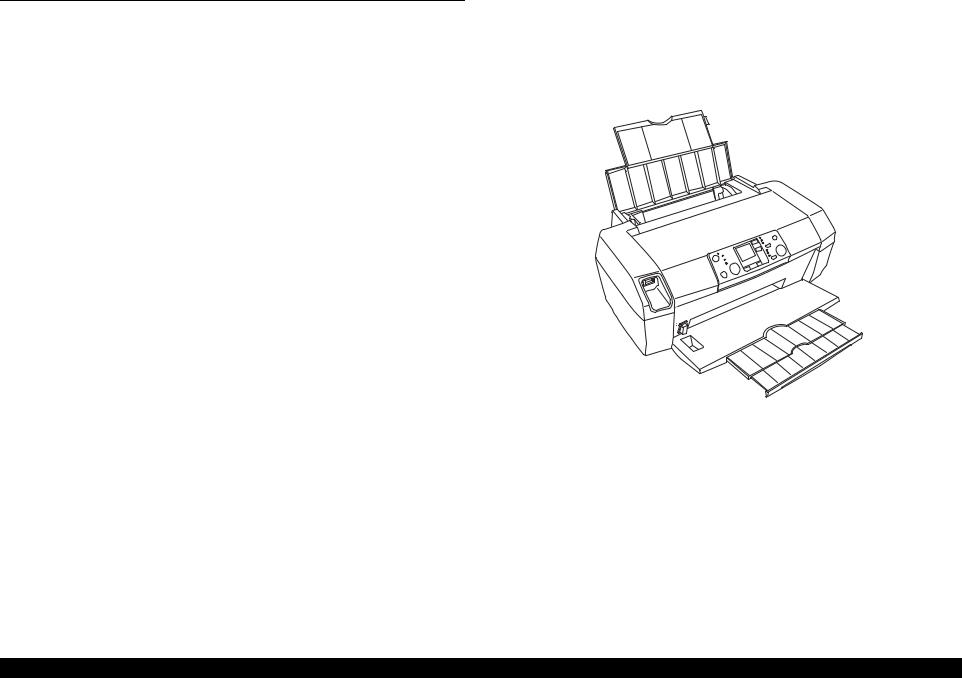
This unit has operation panel on the front side, which becomes more distinctive but still easier to use.
Figure 1-1. Product’s external view
PRODUCT DESCRIPTION |
Overview |
10 |

EPSON Stylus Photo R240/R245/R250/ME PHOTO 20 |
Revision C |
1.2 Specifications
1.2.1 Printer specifications
This section covers specifications of the printer.
1.2.1.1 Physical Specification
Weight
5.0kg (without the ink cartridges)
Dimension (Including rubber feet, not including loading tray) 435.9mm (W) x 268.2mm (D) x 171.2mm (H)
1.2.1.2 Printing Specification
Print Method
On demand ink jet
Nozzle Configuration
|
Black: |
90 nozzles |
|
|
|
|
|
|
|
|
Color: |
90 nozzles x 3 (Cyan, Magenta, Yellow) |
|
|
|
|
|||
|
|
2.822 |
8.467 |
2.822 |
0.07055 |
(1/360inch) |
0.1411 |
(2/360inch) |
|
|
|
(40/360inch) |
(120/360inch) |
(40/360inch) |
|||||
|
|
#A90 |
#B90 |
#C90 |
#D90 |
||||
|
PaperFeed Direction |
|
|
|
|
|
|||
|
#B89 |
#C89 |
#D89 |
|
|
|
|
||
|
#A89 |
|
|
|
|
||||
|
#B88 |
#C88 |
#D88 |
|
|
|
|
||
|
#A88 |
|
|
|
(3/360inch) |
||||
|
|
|
|
|
|
|
|||
|
A row |
B row |
C row |
D row |
|
|
0.2117 |
||
|
|
#B3 |
#C3 |
#D3 |
|
|
|||
|
#A3 |
#D2 |
|
|
|||||
|
#B2 |
#C2 |
|
|
|||||
|
#A2 |
|
|
|
|||||
|
#C1 |
|
|
|
|||||
|
|
#A1 |
#B1 |
#D1 |
|
|
|
|
|
|
|
Cyan |
Magenta |
Yellow |
Black |
|
|
|
|
Carriage Moving Direction
Figure 1-2. Nozzle configuration
1.2.1.3 Paper Support
Cut sheets
Table 1-1. Cut Sheets
Paper size |
|
Dimensions |
Thickness |
Weight |
Paper type |
|
|
|
|
||||||
|
Width (PW) |
Length (PL) |
|
||||
|
|
|
|
|
|
||
|
|
|
|
|
|
|
|
A4 |
|
210 mm |
297 mm |
|
|
|
|
|
|
|
|
|
|
|
|
Executive |
|
184.2 mm |
266.7 mm |
|
|
|
|
|
|
(7.25") |
(10.5") |
|
|
|
|
B5 |
|
182 mm |
257 mm |
|
|
|
|
|
|
|
|
|
64-90 g/m2 |
Plain paper |
|
A5 |
|
148 mm |
210 mm |
0.08-0.11 mm |
|||
Half Letter |
|
139.7 mm |
215.9 mm |
|
(17-24(lb)) |
Recycled paper |
|
|
|
|
|
|
|||
|
|
(5.5") |
(8.5") |
|
|
|
|
|
|
|
|
|
|
|
|
A6 |
|
105 mm |
148 mm |
|
|
|
|
User |
|
50.8-329 mm |
127-1117.6 mm |
|
|
|
|
Defined |
|
|
|
|
|
|
|
|
|
|
|
|
|
|
|
|
|
|
|||||
CAUTION |
It is necessary that there is no wrinkle, nap, tear, fold, so on in |
||||||
|
|
the form. |
|
|
|
|
|
The curve of form must be 5mm or below.
PRODUCT DESCRIPTION |
Specifications |
11 |
EPSON Stylus Photo R240/R245/R250/ME PHOTO 20 |
Revision C |
Envelopes
Table 1-2. Envelopes
Paper size |
Dimensions |
Thickness |
Weight |
Paper type |
|
||
Width (PW) |
Length (PL) |
|
|||||
|
|
|
|
|
|
||
No.10* |
104.8mm |
241.3mm |
N/A |
75-90g/m2 |
Bond paper |
|
|
|
|
(4.125") |
(9.5") |
|
(20-24(lb)) |
Air mail |
|
DL* |
110mm |
220mm |
|
|
PPC |
|
|
C6* |
114mm |
162mm |
|
|
|
|
|
220 x 132* |
132mm |
220mm |
0.1 |
82g/m2 |
|
|
|
|
|
|
|
|
(22(lb)) |
|
|
Note *: Check that the flap is on the long edge and can be folded. |
|
|
|||||
|
|
|
|
||||
CAUTION |
Poor quality paper may reduce print quality and cause paper |
|
|||||
|
|
jams or other problems. If you encounter problems, switch to a |
|
||||
|
|
higher grade of paper. |
|
|
|
|
|
It is necessary that there is no wrinkle, nap, tear, fold, so on in the form.
Don’t use the adhesive envelopes.
Don’t use sleeve insert envelopes and cellophane window envelopes.
The curve and swell of the form must be 3mm or below
Exclusive papers
Quality: EPSON Exclusive paper
Transparency printing is only available at normal temperature.
Table 1-3. Exclusive Papers
Item |
Size |
Width |
Length |
Thickness |
Weight |
|
(PW) |
(PL) |
(mm) |
(g/m2) |
|||
|
|
|||||
Premium Ink Jet Plain Paper *1 |
A4 |
210 |
297 |
0.11 |
80 |
|
Bright White Ink Jet Paper |
A4 |
210 |
297 |
0.13 |
92.5 |
|
Photo Quality Ink Jet Cards |
8" x 10" |
203.2 |
254 |
0.21 |
180 |
|
|
|
|
|
|
|
|
|
5" x 8" |
127 |
203.2 |
|
|
|
|
A6 |
105 |
148 |
|
|
|
|
|
|
|
|
|
|
Photo Quality Self Adhesive Sheets |
A4 |
210 |
297 |
0.19 |
167 |
|
|
|
|
|
|
|
Table 1-3. Exclusive Papers
|
Item |
Size |
Width |
Length |
Thickness |
Weight |
|
(PW) |
(PL) |
(mm) |
(g/m2) |
||
|
|
|
||||
Photo Paper |
|
A4*1 |
210 |
297 |
0.23 |
194 |
|
|
4" x 6" |
101.6 |
152.4 |
|
|
Photo Stickers 4/16 |
A6 |
105 |
148 |
0.19 |
N/A |
|
|
|
|
|
|
|
|
Premium Glossy Photo Paper |
A4 |
210 |
297 |
0.27 |
255 |
|
|
|
5" x 7"*1 |
127 |
178 |
|
|
|
|
4" x 6" |
101.6 |
152.4 |
|
|
|
|
3R*2 |
89 |
127 |
|
|
Glossy Photo Paper |
A4 |
210 |
297 |
0.25 |
258 |
|
|
|
5" x 7"*1 |
127 |
178 |
|
|
|
|
4" x 6" |
101.6 |
152.4 |
|
|
Premium Semigloss Photo Paper |
A4 |
210 |
297 |
0.27 |
250 |
|
|
|
|
|
|
|
|
|
|
4" x 6" |
101.6 |
152.4 |
|
|
Matte Paper-Heavyweight |
A4 |
210 |
297 |
0.23 |
167 |
|
|
|
|
|
|
|
|
Double-sided Matte Paper |
A4 |
210 |
297 |
0.25 |
178 |
|
Economy Photo Paper *2 |
A4 |
210 |
297 |
0.23 |
188 |
|
Iron-On Cool Peel Transfer Paper |
A4 |
210 |
297 |
0.14 |
130 |
|
Photo Quality Ink Jet paper |
A4 |
210 |
298 |
0.12 |
102 |
|
|
|
|
|
|
|
|
Note *1: Only for Stylus Photo R240/R245. |
|
|
|
|
||
*2: Only for Stylus Photo R250/ME PHOTO 20. |
|
|
|
|||
|
|
|||||
CAUTION |
It is necessary that there is no wrinkle, nap, tear, fold, so on in |
|||||
|
the form. |
|
|
|
|
|
The curve of form must be 5mm or below.
PRODUCT DESCRIPTION |
Specifications |
12 |

EPSON Stylus Photo R240/R245/R250/ME PHOTO 20
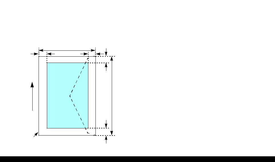
1.2.1.4 Printing Area
Cut sheet (standard printing)
Printable area
The print quality is guaranteed for the print area above the 3mm bottom margin. For paper width (PW) and paper length (PL), refer to “1.2.1.3 Paper Support” (p.11).
Refer to the following table.
As for each margin area, refer to Figure 1-3 (p.13).
Table 1-4. Printing Area
Left Margin |
Right Margin |
Top Margin |
Bottom Margin |
3mm (0.12") |
3mm (0.12") |
3mm (0.12") |
3mm (0.12") |
|
|
|
|
NOTE: Printouts may get dirt with a bottom margin of less than 28.3mm or a top margin of less than 32.1mm because of an unexpected contact of the Printhead.
In addition, with a bottom margin of less than 28.3mm, printed image near the bottom may be distorted.
|
PW |
|
LM |
|
RM |
|
|
TM |
Direction |
|
|
FeedPaper |
Printable area |
PL |
|
||
|
|
BM |
Paper size |
|
|
Figure 1-3. Printable area Cut sheet (standard printing)
Revision C
Cut sheet (border-free printing)
Printable area
For paper width (PW) and paper length (PL), refer to “1.2.1.3 Paper Support” (p.11).
Refer to the following table.
As for each overhang area, refer to Figure 1-4 (p.13).
Table 1-5. Printing Area
Paper size |
Left Overhang |
Right Overhang |
Top Overhang |
|
|
|
|
Bottom Overhang |
||||||||||||||||||||||||||
|
|
|
|
|||||||||||||||||||||||||||||||
|
|
|
|
|
|
|
|
|
|
|
|
|
|
|
|
|
|
|
|
|
|
|
|
|
|
|
|
|
|
|
|
|
|
|
Photo card |
|
|
1.83 mm |
1.83 mm |
2.54 mm |
|
|
|
|
|
|
|
|
|
|
|
|
|
3.53 mm |
|||||||||||||||
|
|
|
|
|
|
|
|
|
|
|
|
|
|
|
|
|
|
|
|
|
|
|
|
|
|
|
|
|
|
|
|
|
|
|
4hx6h/10x15 |
|
|
2.54 mm |
2.54 mm |
1.34 mm |
|
|
|
|
|
|
|
|
|
|
|
|
|
2.54 mm |
|||||||||||||||
Other |
|
|
2.54 mm |
2.54 mm |
2.96 mm |
|
|
|
|
|
|
|
|
|
|
|
|
|
4.02 mm |
|||||||||||||||
|
|
|
|
|
|
|
|
|
|
|
|
|
|
|
|
|
|
|
|
|
|
|
|
|
|
|
|
|
|
|
|
|
|
|
|
|
|
|
LO |
PW |
|
RO |
|
|
|
|
|
|
|
|
|
|
|
|
|
|
|
|
TO |
||||||||||
|
|
|
|
|
|
|
|
|
|
|
|
|
|
|
|
|
|
|
|
|
||||||||||||||
|
|
|
|
|
|
|
|
|
|
|
|
|
|
|
|
|
|
|
|
|
|
|
|
|
|
|
|
|
|
|
|
|
|
|
|
|
|
|
|
|
|
|
|
|
|
|
|
|
|
|
|
|
|
|
|
|
|
|
|
|
|
|
|
|
|
|
|
|
|
|
|
|
|
|
|
|
|
|
|
|
|
|
|
|
|
|
|
|
|
|
|
|
|
|
|
|
|
|
|
|
|
|
|
|
|
|
|
|
|
|
|
|
|
|
|
|
|
|
|
|
|
|
|
|
|
|
|
|
|
|
|
|
|
|
|
|
|
|
|
Direction |
|
|
|
|
|
Paper Feed |
Paper size |
PL |
|
|
|
|
|
|
|
|
|
 BO Printable area
Figure 1-4. Printable area for Cut sheet (border-free printing)
PRODUCT DESCRIPTION |
Specifications |
13 |
EPSON Stylus Photo R240/R245/R250/ME PHOTO 20 |
Revision C |
Envelopes
Printable area
For paper width (PW) and paper length (PL), refer to “1.2.1.3 Paper Support” (p.11).
Refer to the following table.
As for each margin area, refer to Figure 1-5 (p.14).
Table 1-6. Printing Area
Left Margin |
Right Margin |
Top Margin |
Bottom Margin |
3mm (0.12") |
3mm (0.12") |
5mm (0.20") |
20mm (0.79") |
|
|
|
|
NOTE: Printouts may get dirt with a bottom margin of less than 20.0mm or a top margin of less than 32.1mm because of an unexpected contact of the Printhead.
In addition, with a bottom margin of less than 20.0mm, printed image near the bottom may be distorted.
|
PW |
|
LM |
RM |
|
|
TM |
|
|
Printable area |
|
Direction |
PL |
|
Paper Feed |
||
|
||
|
BM |
Paper size
Figure 1-5. Printable area for envelopes
PRODUCT DESCRIPTION |
Specifications |
14 |
EPSON Stylus Photo R240/R245/R250/ME PHOTO 20 |
Revision C |
1.2.1.5 Ink Cartridge Specification
Type/color: |
EPSON-brand special ink cartridges |
|||
|
|
Table 1-7. Ink Cartridge |
|
|
|
|
|
|
|
Color |
Stylus Photo R240/R245 |
Stylus Photo R250 |
ME PHOTO 20 |
|
Black |
T0551 |
|
T0561 |
T0841 |
|
|
|
|
|
Cyan |
T0552 |
|
T0562 |
T0842 |
Magenta |
T0553 |
|
T0563 |
T0843 |
|
|
|
|
|
Yellow |
T0554 |
|
T0564 |
T0844 |
Shelf life: |
After packing is opened, it is assumed 6 months, and |
|||
|
|
assumes two years including this. |
||
Storage Temperature |
|
|
|
|
|
Table 1-8. Storage Temperature |
|
||
|
|
|
|
|
|
Situation |
|
Storage Temperature |
Limit |
When stored in individual boxes |
|
-30 oC ~ 40 oC |
1 month max. at 40 oC |
|
When installed in main unit |
|
-20 oC ~ 40 oC |
|
|
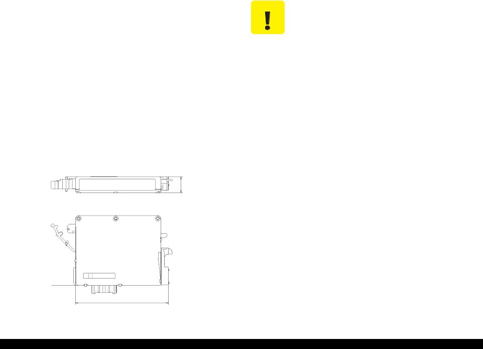
Dimension: |
12.7mm (W) x 73.46mm (D) x 55.25mm (H) |
|||
|
|
|
|
12.7mm |
Base View
73.46mm
Figure 1-6. Ink cartridge
CAUTION |
The ink in the ink cartridge freezes when leaving it in the |
|
environment of -16°C or under. It takes 3 hours that the frozen ink |
|
becomes usable when moving it from the environment of -20°C to |
|
the environment of 25°C. |
|
|
1.2.1.6 Electric Specification
Primary power input
Table 1-9. Primary power input
|
100-120V model |
|
220-240V model |
|
Rated power supply voltage (VAC) |
100 ~ 120 |
|
|
220 ~ 240 |
|
|
|
|
|
Input voltage range (VAC) |
90 ~ 132 |
|
|
198 ~ 264 |
Rated current (A) |
0.4 (Max. 0.7) |
|
|
0.2 (Max. 0.3) |
|
|
|
|
|
Rated frequency (Hz) |
|
|
50 ~ 60 |
|
Input frequency range (Hz) |
|
49.5 ~ 60.5 |
||
|
|
|
|
|
Power consumption (W) |
|
Approx. 10W |
||
|
(Standalone copying, ISO10561 Letter Patter, |
|||
|
Plain Paper - Text) |
|||
|
|
Approx. 1.5W |
||
|
|
(Sleep Mode) |
||
|
|
|
|
|
|
Approx. 0.2W |
|
|
Approx. 0.4W |
|
(Power Off Mode) |
|
(Power Off Mode) |
|
|
|
|
|
|
NOTE 1: This product complies with the “Energy Star” standards.
2:If the printer is not operated at all for at least three minutes, the standby function reduces the current to the motor to conserve power.
3:If the panel button is not operated at all for at least 13 minutes, the LCD panel is go out.s
PRODUCT DESCRIPTION |
Specifications |
15 |
EPSON Stylus Photo R240/R245/R250/ME PHOTO 20 |
Revision C |
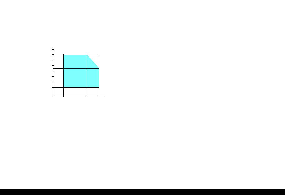
1.2.1.7 Environmental Performance
Table 1-10. Environmental Performance
|
|
Condition |
Temperature |
Humidity*2 |
|
|
|
Operating |
|
10 ~ 35°C*3 |
20 ~ 80% *3 |
|
|
Not operating*1 |
|
-20 ~ 40°C*4 |
5 ~ 85% |
Note *1: |
After unpacking (storage) |
|
|
||
*2: |
No condensation |
|
|
||
*3: |
Under the following conditions |
|
|||
*4: |
One month when at 40°C |
|
|
||
90
80
70
60
Humidity (%) 50
40
30
20
|
|
|
|
27 |
|
|
|
|
|
|
10 |
20 |
30 |
35 |
40 |
||||||
Temperature (°C)
Figure 1-7. Temperature/Humidity range
1.2.1.8 Durability
|
Total print life: |
10,000 pages (black only, A4), or five years |
|
|
(whichever comes first) |
|
Print Head Life: |
Six billion shots (per nozzle) or five years |
|
|
(whichever comes first) |
1.2.1.9 Safety Standards: EMC
220-240V model
|
Safety standards: |
EN 60950 |
|
EMI: |
EN 55022(CISPR Pub.22) class B |
|
|
AS/NZS CISPR22 class B |
1.2.1.10 CE Marking
220-240V model
Low Voltage Directive 73/23/EEC: EN60950
EMC Directive 89/336/EEC: |
EN55022 Class B |
|
EN61000-3-2 |
|
EN61000-3-3 |
|
EN55024 |
PRODUCT DESCRIPTION |
Specifications |
16 |

EPSON Stylus Photo R240/R245/R250/ME PHOTO 20 |
Revision C |
1.3 Interface
The EPSON Stylus Photo R240/R245/R250/ME PHOTO 20 provides the following interface.
1.3.1 USB Interface
Standards
“Universal Serial Bus Specifications Revision 2.0”
“Universal Serial Bus Device Class Definition for Printing Devices Version 1.1” (printer unit)
“Universal Serial Bus Mass Storage Class Bulk-Only Transport Revision 1.0” (storage unit)
Transfer rate: |
480 Mbps (High Speed Device) |
|
Data format: |
NRZI |
|
|
Compatible connector: |
USB Series B |
|
Recommended cable length: |
2 [m] or less |
Connector signal layout
Table 1-11. Connector pin assignment and signals
Pin No. |
Signal name |
I/O |
|
|
|
|
|
|
Function description |
|||||
1 |
VCC |
--- |
|
|
|
|
Cable power. Max. power consumption is 2mA. |
|||||||
|
|
|
|
|
|
|
|
|
|
|
|
|
|
|
2 |
-Data |
Bi-D |
Data |
|||||||||||
3 |
+Data |
Bi-D |
Data, pull up to +3.3V via 1.5K ohm resistor. |
|||||||||||
|
|
|
|
|
|
|
|
|
|
|
|
|
|
|
4 |
Ground |
--- |
|
|
|
|
Cable ground |
|||||||
|
|
Pin #2 |
|
|
|
|
Pin #1 |
|||||||
|
|
|
|
|
|
|
|
|
|
|
|
|
|
|
|
|
|
|
|
|
|
|
|
|
|
|
|
|
|
|
|
|
|
|
|
|
|
|
|
|
|
|
|
|
|
|
|
|
|
|
|
|
|
|
|
|
|
|
|
|
|
|
|
|
|
|
|
|
|
|
|
|
|
|
|
|
|
|
|
|
|
|
|
|
|
|
|
|
|
|
|
|
|
|
|
|
|
|
|
|
|
|
|
|
|
|
|
|
|
Pin #3 |
Pin #4 |
|||
Figure 1-8. USB pin Assignment
PRODUCT DESCRIPTION |
Interface |
17 |

EPSON Stylus Photo R240/R245/R250/ME PHOTO 20 |
Revision C |
1.3.2 Standard Card Slots
1.3.2.1 Memory card
Table 1-12. Memory card
Memory card standards |
Slots |
Supported memory cards |
|
Compact |
CF+ and CompactFlash |
CF Type II slot |
• CompactFlash |
Flash |
Specification Revision 1.4 |
|
(memory card only) |
|
compliant |
|
• Microdrive |
|
|
|
|
SmartMedia |
SmartMedia Standard 2003 |
SmartMedia slot |
• SmartMedia |
|
compliant |
|
(maximum capacity: 128 MB) |
Memory |
Memory Stick Standard |
Memory Stick/ |
• Memory Stick |
Stick |
version 1.3 compliant |
Memory Stick |
(maximum capacity: 128 MB, |
|
|
PRO slot |
including versions with |
|
|
|
memory select function) |
|
|
|
• MagicGate Memory Stick |
|
|
|
(maximum capacity: 128 MB, |
|
|
|
copy protection function is not |
|
|
|
supported) |
|
|
|
• Memory Stick Duo |
|
|
|
(requires Memory Stick Duo |
|
|
|
adapter) |
|
|
|
• MagicGate Memory Stick Duo |
|
|
|
|
Memory |
MemoryStick Standard |
|
• Memory Stick PRO |
Stick PRO |
Memory Stick PRO Format |
|
(copy protection function is not |
|
Specifications version 1.0 |
|
supported) |
|
compliant |
|
• Memory Stick PRO Duo |
|
|
|
(requires Memory Stick Duo |
|
|
|
adapter) |
SD |
SD Memory Card |
SD/MMC slot |
• SD (Secure Digital) memory |
|
Specifications/PART1. |
|
card |
|
Physical Layer Specification |
|
• miniSD card |
|
Version 1.0 compliant |
|
(requires SD adapter) |
|
|
|
|
MultiMedia |
MultiMediaCard Standard |
|
MultiMediaCard |
Card |
compliant |
|
|
xD-Picture |
xD-Picture CardTM Card |
xD-Picture Card |
• xD-Picture Card |
Card |
Specification Version 1.20 |
slot |
• xD-Picture Card Type M |
|
Type M compliant |
|
|
CAUTION |
Note the following caution points when handling the memory card. |
|
|
|
Since the SD card and Memory Stick share the same slot, only |
|
|
one can be inserted at a time. |
|
|
Since the SmartMedia and xD-Picture Card share the same |
|
|
slot, only one can be inserted at a time. |
When a memory card is being accessed, be sure to keep the memory card slot’s cover closed and do not touch the memory card.
1.3.2.2Supported power supply voltage
3.3V/5V (both)
3.3V (only)
NOTE 1: 3.3V power is supplied to media that support both 3.3V and 5V.
2:Maximum current to memory card is 500mA.
3:5V type memory cards are not supported.
PRODUCT DESCRIPTION |
Interface |
18 |

EPSON Stylus Photo R240/R245/R250/ME PHOTO 20 |
Revision C |
1.3.2.3 Multi-slot operations |
Details |
|
Overview |
Access priority |
|
There is only one type of card that can be used to simultaneously access both |
The access priority among slots is assigned as: |
|
|
||
a connected computer and the direct printing function. |
1: CF (Microdrive) |
|
The slots have assigned priority to determine which slot will be accessed first |
2: SmartMedia/xD-Picture Card |
|
3: Memory Stick (Memory Stick PRO)/SD (MMC) |
||
when cards are inserted in several slots at once. |
||
To select a card that has been inserted in a non-active slot, the card in the |
Slot selection when power is turned on |
|
active slot must first be removed. |
If cards are inserted in several slots when the power is turned on, the active |
|
• Direct printing |
slot is determined by the priority ranks listed above. |
|
Example: If Smart Media and Memory Stick are both inserted at power-on, |
||
Only the image files in the active slot are valid and have assigned frame |
||
numbers. The number of images will not change if a card is also inserted in |
the SmartMedia slot becomes the active slot. |
|
a non-selected slot. |
Slot selection after power is turned on |
|
• Connection to computer (Windows) |
||
When a card is removed from the active slot, the slot with the next-highest |
||
Only one drive is displayed at a time as a “removable disk” and only the |
||
priority becomes the active slot (if a card has been inserted into it). There is no |
||
card that is in the active slot can be accessed via the removable disk. A card |
||
need to re-insert any card before accessing it. If no slots contain any cards, the |
||
that has been inserted into a non-selected slot cannot be accessed. |
||
highest-priority slot (CF Microdrive) again becomes the active slot. |
||
• Connection to computer (Macintosh) |
||
Cards can be removed from non-selected slots in any order. |
||
Only the card in the active slot can be mounted on the desktop. A card that |
||
Example: If a memory stick and CF card are inserted while SmartMedia is |
||
has been inserted into a non-selected slot cannot be mounted on the desktop. |
||
|
selected, CF becomes selected (active) once SmartMedia is |
|
|
removed. |
PRODUCT DESCRIPTION |
Interface |
19 |

EPSON Stylus Photo R240/R245/R250/ME PHOTO 20 |
Revision C |
1.4 Memory Card Print
1.4.1 Basic Specifications
1.4.1.1 File system
DCF Version 1.0 or 2.0 is the file system that can be used with this unit’s stand-alone printing functions. Operation is not guaranteed when any other file system is used. The file system used by the card reader function depends on the host’s specifications. For a detailed description of the DCF specifications, see the “Design Rule for Camera File System Standard, DCF Version 2.0, JEIDA-CP-3461”.
1.4.1.2 Media format
Media must be formatted according to the DCF Version 1.0 or 2.0 standard.
DOS FAT formats (FAT12, FAT16) and single partition (basic partition)
1.4.1.3 File formats
The file formats supported by this unit are described below.
JPEG files (*.JPG)
These are photo data files that comply with the Exif Version 2.21 standard. (Exif version 1.0/2.0/2.1/2.2/2.21)
Camera specification files (*.MRK)
These are definition files used when in camera specification mode. An “AUTOPRINT.MRK” file whose full path name is no longer than 32 characters is valid.
PRINT Image Framer (P.I.F.) definition file (*.USD)
File to define the layout in accordance with the PRINT Image Framer specifications. Files only in the “¥EPUDL¥” directory are available. Compatible with Print Image Framer Rev.2.1.
PRINT Image Framer (P.I.F.) definition file (*.FD2)
File to define the layout in accordance with the PRINT Image Framer specifications. All files in the memory card are targeted for search. Compatible with Print Image Framer Rev 3.1.
File contents are divided into complete type and template type.
Template type: The frame only on which image data is printed is specified.
Provides nearly identical functions as those supported with the current P.I.F. Rev.3.1.
Complete type: Print layout information, image data and frame data is
contained in one package. Printing is performed using this file only without specifying photos.
Note: As a general rule, this unit will support up to level 1 of P.I.F. Rev.3.1
Note, however, any file that is saved in the following directories or their sub-directories cannot be included as files to be printed.
Directories containing system properties or hidden properties
“RECYCLED”
Windows directory for deleted files
“PREVIEW”
Directories containing CASIO’s DSC thumbnail images
“SCENE”
Directories containing data for CASIO’s DSC Best Shot function
“MSSONY”
Directories containing SONY’s DSC e-mail image data, voice memos, video files, or non-compressed images
“DCIM¥ALBUM¥IMAGE”
CASIO DSC album data save directory
1.4.1.4 Valid image size
The maximum image size handled by this unit is:
|
Horizontal: |
80 ≤ X ≤ 9200 (pixels) |
|
Vertical: |
80 ≤ Y ≤ 9200 (pixels) |
PRODUCT DESCRIPTION |
Memory Card Print |
20 |

EPSON Stylus Photo R240/R245/R250/ME PHOTO 20 |
Revision C |
1.4.1.5 Maximum number of photo data files
This unit can handle up to 999 photo data files. If the amount of photo data to be recorded exceeds the capacity of one memory card, this unit uses file sorting rules to sort the photo data into valid photo data in frames numbered from 1 to 999. Although it is possible to print photo data files with frame numbers over 999 that have been specified for printing by camera specification files, the maximum number of frames that can be specified is 999 frames.
If you insert a memory card that contains over 999 photo data files, only files up to 999 will be printed by the “Print All” or “Print index sheet” functions.
1.4.1.6 Thumbnail image data
This unit handles thumbnail image data in the DCF Version 1.0 or 2.0 format (Exif format, 160 x 120 pixels).
During this unit’s Index sheet and memory card printing modes, the layout is 80 thumbnails per sheet (when using plain paper or special paper in high-speed print mode).
1.4.1.7 File sorting
This unit stores all photo data files in the memory, using the photo data files’ full-path file names (for example, “¥DCIM¥100EPSON¥EPSN0000.JPG”), and assigned photo frame numbers. Since photo frame numbers are assigned based on this unit’s own proprietary file sorting rules, the assigned frame numbers do not necessarily match those indicated by digital cameras.
1.4.1.8 File sorting rules
This unit sorts photo data files based on the following prioritization rule.
File name is sorted in ASCII order as full path name.
Note: Sorting results are not guaranteed if two files have matching fullpath file names. (Matching full-path file names are not allowed under the DOS specification.)
1.4.1.9 Rules for acquisition of date/time data
The following priorities are used to fetch date and time information from photo data files.
1.Date/time data that complies with the standard format (Exif) for digital cameras
2.Date/time data that complies with the DOS standard file system (file time stamps)
3.Fixed values (01/01/1980, 00:00:00)
Note that the date/time data assigned to individual photo data files does not necessarily match the date/time when the photo was actually taken. The photo date/time may be modified due to the digital camera’s calendar settings (presence/absence of functions, incorrect date/time settings, etc.), processing of the photo data after the photo was taken, or subsequent saving of data. In such cases, this unit performs the relevant processing based on the most recently modified date/time data.
1.4.1.10 Number of sheets which can be printed in total
Printing sum total number of sheets presupposes that it is possible to 999 sheets. Moreover, the printing sum total number of sheets per sheet is possible to 99 sheets.
PRODUCT DESCRIPTION |
Memory Card Print |
21 |
EPSON Stylus Photo R240/R245/R250/ME PHOTO 20 |
Revision C |
1.4.2 Functions
1.4.2.1 List of functions
The memory card print menu and its settings are listed in the following table. The values shown in this table indicate the total number of options and the number of pages or copies that can be printed consecutively.
Table 1-13. List of functions
Memory card |
Mode selection |
Layout |
Paper type |
Paper |
Page/ |
|
printing |
size |
copies |
||||
|
|
|
||||
|
|
|
|
|
|
|
Print selected |
Print Select |
• Standard |
• Plain Paper |
3 |
1 |
|
image*1 |
|
• Border free |
• Photo Paper |
|
|
|
|
|
• Border free |
• Matte Paper |
|
|
|
|
|
|
|
|
|
|
Print all images |
Print All/ |
• Standard |
• Plain Paper |
3 |
1 |
|
|
PictBridge |
• Border free |
• Photo Paper |
|
|
|
|
|
• Border free |
• Matte Paper |
|
|
|
DPOF*2 |
Print Select |
• Standard |
• Plain Paper |
3 |
1 to 99 |
|
|
|
• Border free |
• Photo Paper |
|
|
|
|
|
• Border free |
• Matte Paper |
|
|
|
|
|
|
|
|
|
|
Print index sheet |
Print Index Sheet |
None |
Plain Paper |
1 |
1 |
|
|
|
|
|
|
|
Note *1: “Print selected image” will be selected as default function of Memory Card Print. *2: It is available only “DPOF” file exists in the memory card.
1.4.2.2 Memory card printing mode
Print selected image
This function prints selected image file stored in the memory card. As shown below, the number of printed pages depends on the number of copies to be printed.
Print all images
This function prints all of the image files stored in the memory card. As shown below, the number of printed pages depends on the number of copies to be printed.
DPOF printing
In this mode, the photo frame numbers previously specified via the camera are printed in the number of pages specified via the camera. Only the paper type and layout are specified on the printer side. If the layout assigned multiple photos per output sheet, photos that have different frame sizes are automatically assigned in the specified number of pages in numerical order (of the specified photo frame
numbers). If index print mode was set via the camera, this unit will print in DPOF index layout. (When in DPOF print mode, the mode cannot be switched by writing the print file specification from the host after inserting the memory card.)
Print index sheet printing
This function prints thumbnail images (stored in the memory card) onto an order sheet (form) that is marked for selecting images.
Table 1-14. Memory card printing mode
Setting |
Memory card printing mode |
Description |
Option, setting range, etc. |
|
|
|
|
Layout |
• Print selected image |
Sets print |
Fixed in combination with paper type |
(no menu) |
• Print all images |
layout |
and paper size (refer to “1.4.3 Layout |
|
• DPOF printing |
|
and Paper Type, Paper Size” (p.23)) |
|
|
|
|
|
|
|
|
Paper type |
• Print selected image |
Sets paper |
Plain Paper, Photo Paper or Matte |
|
• Print all images |
type |
paper |
|
• DPOF printing |
|
|
|
Print index sheet printing |
Fixed |
Plain Paper |
Paper size |
• Print selected image |
Sets paper |
A4, 10x15/4”x6” or 13x18/5”x7” |
|
• Print all images |
size |
|
|
• DPOF printing |
|
|
|
Print index sheet printing |
Fixed |
A4 |
|
|
|
|
Pages/ |
Print selected image |
Sets number |
1 to 99 copies (default is 1 copy). |
copies |
Print all images |
of printout |
1 |
|
|
|
|
|
DPOF printing |
|
The number of copies specified via |
|
|
|
the camera is used. |
|
|
|
The setting range is 1 to 99 copies |
|
|
|
(default is 1 copy). |
|
Print index sheet printing |
Fixed |
Fixed as 1 page (can vary according |
|
|
|
to the number of image files) |
Quality |
• Print selected image |
Sets print |
Fixed according to paper type (refer |
|
• Print all images |
quality |
to “1.4.7 Relation between Paper |
|
• DPOF printing |
|
Type and Quality” (p.27)) |
|
|
|
|
|
Print index sheet printing |
Fixed |
Prints it by the quality of Plain Paper. |
|
|
|
Only the Color print is |
|
|
|
supported. |
|
|
|
|
PRODUCT DESCRIPTION |
Memory Card Print |
22 |
EPSON Stylus Photo R240/R245/R250/ME PHOTO 20 |
Revision C |
1.4.3 Layout and Paper Type, Paper Size
The layout/paper type and size combinations that can be selected are listed below.
Table 1-15. Layout and Paper Type, Paper Size
Layout |
Paper type |
Paper size |
Description |
Border free |
Photo Paper |
A4 |
Prints with no margins along top, bottom and both |
|
|
10x15 |
sides |
|
|
13x18 |
|
|
|
|
|
1-up with |
Plain Paper |
A4 |
Prints with 3mm margins along top, bottom and |
borders |
|
10x15 |
both sides |
|
|
13x18 |
|
20-up |
--- |
10x15 |
Prints 20 frames per page, laid out in 5 columns and |
|
|
13x18 |
4 rows (For DPOF index print only) |
|
|
|
|
30-up |
--- |
13x18 |
Prints 30 frames per page, laid out in 5 columns and |
|
|
|
4 rows (For DPOF index print only) |
80-up |
--- |
10x15 |
Prints 80 frames per page, laid out in 10 columns |
|
|
13x18 |
and 8 rows (For DPOF index print only) |
|
|
|
|
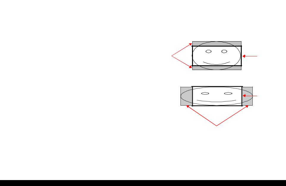
1.4.4 Trimming Function
A trimming function is provided as a means of coordinating photo data with the types of photo frames handled by this unit. This function is always activated so that printing photo data is in shapes that fit these photo frames.
This function is described briefly below.
The printed photo frame and the photo to be printed are matched in length along one side and the photo is resized along the perpendicular side to fit the frame on that side. Any part of the photo that does not fit within the photo frame is trimmed away (not printed).
The image below shows an example in which the photo data is aligned vertically with the photo frame.
These parts are |
Photo frame |
trimmed. |
(print area) |
The image below shows an example in which the photo data is aligned horizontally with the photo frame.
Photo frame (print area)
These parts are trimmed.
Figure 1-9. Trimming Function
PRODUCT DESCRIPTION |
Memory Card Print |
23 |
EPSON Stylus Photo R240/R245/R250/ME PHOTO 20 |
Revision C |
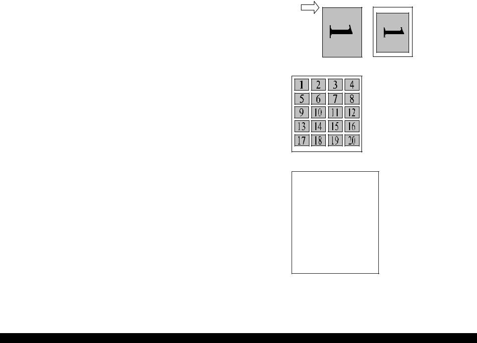
1.4.5Assignment Rules for Photo Frame Numbers and Rotation
The rules concerning photo frame numbers that are referenced when assigning photos are described below. The numbers shown in each diagram and photo frame below indicate the photo frame numbers used for various types of layout.
The direction of the number shown in each photo frame matches the direction of the printed photo to which the horizontal photo data was allocated. When there are more pixels vertically than horizontally, the vertical photo data is allocated instead, and the number shown in the figure below is then rotated 90° before being printed. In Index printing mode, the numbers are printed as they are shown below, regardless of the shape of the photo data.
However, when the photo data has an equal number of pixels vertically and horizontally the photos are printed without rotation, regardless of the layout.
NOTE: The vertical photo data refers to when the photo data file itself is set for a vertical (portrait) orientation. Photo data is defined as the vertical photo data if it is taken by a digital camera with a portrait position detecting function.)
Top edge
<Border-free> |
<1 sheet with borders> |
<20-up> |
|
|
|
|
|
|
|
|
1 |
2 |
3 |
4 |
5 |
|
|
6 |
7 |
8 |
9 |
10 |
|
|
11 |
12 |
13 |
14 |
15 |
|
|
16 |
17 |
18 |
19 |
20 |
|
|
21 |
22 |
23 |
24 |
25 |
|
|
25 |
26 |
27 |
28 |
30 |
|
|
|
|
|
|
|
|
|
|
<30-up> |
|
|
||
1 |
2 |
3 |
4 |
5 |
6 |
7 |
8 |
9 |
10 |
11 |
12 |
13 |
14 |
15 |
16 |
17 |
18 |
19 |
20 |
21 |
22 |
23 |
24 |
25 |
26 |
27 |
28 |
29 |
30 |
31 |
32 |
33 |
34 |
35 |
36 |
37 |
38 |
39 |
40 |
41 |
42 |
43 |
44 |
45 |
46 |
47 |
48 |
49 |
50 |
51 |
52 |
53 |
54 |
55 |
56 |
57 |
58 |
59 |
60 |
61 |
62 |
63 |
64 |
65 |
66 |
67 |
68 |
69 |
70 |
71 |
72 |
73 |
74 |
75 |
76 |
77 |
78 |
79 |
80 |
<80-up>
Figure 1-10. Assignment Rules for Photo Frame Numbers and Rotation
PRODUCT DESCRIPTION |
Memory Card Print |
24 |
EPSON Stylus Photo R240/R245/R250/ME PHOTO 20 |
Revision C |
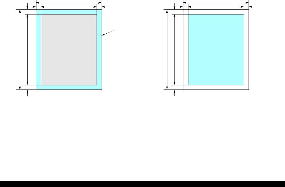
1.4.6 Layout Drawings
1.4.6.1 Border free
|
|
C |
|
G |
E |
A |
F |
Printable
area
D B |
Paper |
|
1.4.6.2 |
1-up with borders |
|
|
|
|
|
|
A |
|
|
G |
E |
C |
F |
B D |
Printable area |
|
H
Figure 1-11. Border free
Table 1-16. Border free (unit: mm)
Paper type |
A |
B |
C |
D |
E |
F |
G |
H |
A4 |
210 |
297 |
215.08 |
305.04 |
2.54 |
2.54 |
2.96 |
4.02 |
|
|
|
|
|
|
|
|
|
10x15 |
101.6 |
152.4 |
106.68 |
160.53 |
2.54 |
2.54 |
2.82 |
3.6 |
13x18 |
127 |
178 |
132.08 |
186.04 |
2.54 |
2.54 |
2.96 |
4.02 |
|
|
|
|
|
|
|
|
|
H
Figure 1-12. 1-up with borders
Table 1-17. 1-up with borders (unit: mm)
Paper type |
A |
B |
C |
D |
E |
F |
G |
H |
|
|
|
|
|
|
|
|
|
|
|
A4 |
210 |
297 |
204 |
291 |
3 |
3 |
3 |
3 |
|
|
|
|
|
|
|
|
|
|
|
10x15 |
101.6 |
152.4 |
95.6 |
146.4 |
3 |
3 |
3 |
3 |
|
13x18 |
127 |
178 |
121 |
172 |
3 |
3 |
3 |
3 |
|
|
|
|
|
|
|
|
|
|
PRODUCT DESCRIPTION |
Memory Card Print |
25 |
EPSON Stylus Photo R240/R245/R250/ME PHOTO 20 |
Revision C |
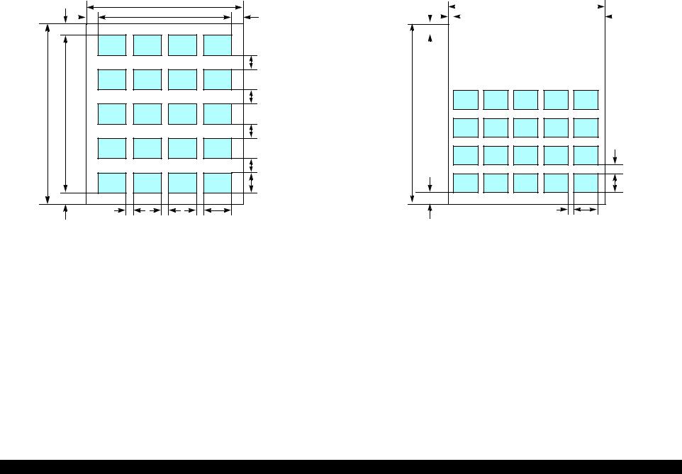
1.4.6.3 20-up
|
|
A |
|
G |
E |
K |
F |
J |
J |
B |
L |
|
J |
J |
D |
H |
I |
I |
I |
C |
|
Figure 1-13. 20-up
Table 1-18. 20-up (unit: mm)
Paper |
A |
B |
C |
D |
E |
F |
G |
H |
I |
J |
K |
L |
|
type |
|||||||||||||
|
|
|
|
|
|
|
|
|
|
|
|
||
10x15 |
101.6 |
152.4 |
20 |
20 |
6.1 |
6.3 |
19.8 |
20.3 |
3 |
3 |
89.3 |
112.3 |
|
|
|
|
|
|
|
|
|
|
|
|
|
|
|
13x18 |
127 |
178 |
29 |
24.6 |
3 |
3 |
5 |
10 |
1.7 |
10 |
121 |
163 |
|
|
|
|
|
|
|
|
|
|
|
|
|
|
1.4.6.4 30-up
A
G |
|
E |
|
|
|
|
|
|
|
|
|
|
|
|
|
|
F |
|
|
|
|
|
|
|
|
|
|
|
|
|
|
||||||
|
|
|
|
|
|
|
|
|
|
|
|
|
|
|
|
|
|
|
|
|
|
|
|
|
|
|
|
|
|
|
|
|
|
|
|
|
|
|
|
|
|
|
|
|
|
|
|
|
|
|
|
|
|
|
|
|
|
|
|
|
|
|
|
|
|
|
|
|
|
|
|
|
|
|
|
|
|
|
|
|
|
|
|
|
|
|
|
|
|
|
|
|
|
|
|
|
|
|
|
|
|
|
|
|
|
|
|
|
|
|
|
|
|
|
|
|
|
|
|
|
|
|
|
|
|
|
|
|
|
|
|
|
|
|
|
|
|
|
|
|
|
|
|
|
|
|
|
|
|
|
|
B
J |
D |
H |
C |
I |
Figure 1-14. 30-up
Table 1-19. 30-up (unit: mm)
Paper |
A |
B |
C |
D |
E |
F |
G |
H |
I |
J |
|
type |
|||||||||||
|
|
|
|
|
|
|
|
|
|
||
13x18 |
127 |
178 |
20 |
20 |
4.5 |
4.5 |
14 |
14 |
4.5 |
6 |
|
|
|
|
|
|
|
|
|
|
|
|
PRODUCT DESCRIPTION |
Memory Card Print |
26 |
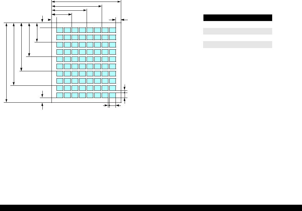
EPSON Stylus Photo R240/R245/R250/ME PHOTO 20 |
Revision C |
1.4.6.5 |
80-up |
|
|
|
|
A |
|
|
|
J |
|
|
|
I |
|
|
|
H |
|
|
L |
G |
K |
|
M |
|
|
|
N |
|
|
|
O |
|
|
P |
|
|
|
B |
|
|
|
|
|
|
F |
|
|
|
D |
|
Q |
E |
C |
|
|
1.4.7 Relation between Paper Type and Quality
In this mode, printing is always in color (CMYK), not black ink only.
Table 1-21. Relation between Paper Type and Quality
Paper type |
Print resolution (H x V dpi) |
Dot size |
|
|
|
Plain Paper |
720 x 720 |
VSD3 |
|
|
|
Photo Paper |
1440 x 720 |
VSD3 |
Matte Paper |
1440 x 720 |
VSD3 |
|
|
|
Index sheet (Plain Paper) |
360 x 360 |
VSD1 |
|
|
|
Figure 1-15. 80-up
Table 1-20. 80-up (unit: mm)
Paper |
A B C D E F G H I J K L M |
N O P Q |
||||||||||||||||
type |
||||||||||||||||||
|
|
|
|
|
|
|
|
|
|
|
|
|
|
|
|
|
||
A4 |
210 |
297 |
20 |
20 |
2 |
5 |
18 |
62 |
106 |
150 |
18 |
26 |
76 |
126 |
176 |
226 |
26 |
|
|
|
|
|
|
|
|
|
|
|
|
|
|
|
|
|
|
|
|
PRODUCT DESCRIPTION |
Memory Card Print |
27 |

EPSON Stylus Photo R240/R245/R250/ME PHOTO 20 |
Revision C |
1.5 USB Direct-Print/PictBridge Functions
The printer can print from Digital Still Camera that is compliant with the following specifications.
1.5.1 Supported Device
USB DIRECT-PRINT
The device that is compliant with “USB DIRECT-PRINT” specification.
CIPA DC-001-2003 Digital Photo Solutions for Imaging Device
The device that is compliant with “CIPA DC-001-2003 Digital Photo Solutions for Imaging Devices” specification.
1.5.2 Functions Available from DSC
Following functions are available.
Implementation of each function depends on the DSC.
Table 1-22. Functions Available from DSC
Function |
USB Direct-Print Functions |
|
PictBridge Functions |
Specify picture |
OK |
|
OK |
|
(single picture or DPOF) |
|
(single picture, multiple pictures |
|
|
|
or DPOF) |
|
|
|
|
Specify paper type |
OK |
|
OK |
|
(Plain paper, Photo paper, |
|
(Plain paper and Glossy paper) |
|
Glossy paper and Matte paper) |
|
|
Specify paper size |
|
OK |
|
|
(A4, 5x7in., 4x6in., 8x10in. and Letter) |
||
|
|
|
|
Specify layout |
OK |
|
OK |
|
(borderless, Single. 2up, 4up, |
|
(borderless, Single, 2up, 4up, |
|
8up are available for DPOF) |
|
8up, 20up and Index) |
Specify date print |
OK |
|
OK |
|
(Enable or Disable) |
|
|
|
|
|
|
|
|
|
|
Specify print quality |
NG |
|
OK |
Automatic correction |
OK |
|
NG |
|
(Enable or Disable) |
|
|
|
|
|
|
Cropping |
OK |
|
OK |
|
(Any area of rectangle. This |
|
(Any area of rectangle) |
|
function is available for Single |
|
|
|
picture print only) |
|
|
|
|
|
|
Table 1-22. Functions Available from DSC
Function |
USB Direct-Print Functions |
|
PictBridge Functions |
PRINT Image Framer |
OK |
|
--- |
|
(Enable or Disable) |
|
|
|
|
|
|
Status acquisition |
|
OK |
|
Start print |
|
OK |
|
|
|
|
|
Stop print immediately |
|
OK |
|
Stop print at the end of page |
|
OK |
|
|
|
|
|
Reset printer |
OK |
|
--- |
|
|
|
|
1.5.3 Operation
1.5.3.1 Preparation
Conditions described below are required before starting printing.
The printer is not printing from the PC.
The printer is not printing from the memory card slot.
The printer is not performing the backup of the memory card.*
The error (paper empty, ink end, etc.) is cleared.
Note *: PictBridge only.
1.5.3.2 Standard Operations
Standard operations are described below. These operations depends on the DSC.
1.Preparation at the printer
Some settings are required before connecting with the DSC. If your DSC can set these settings, preparation at the printer is not required.
1-1. Choose the Paper Type, Paper Size and Layout to the desired setting. 1-2. Change More Options if necessary (e.g. Automatic Correction, Filter and
Date print)
2.Preparation at the DSC
Some operations are necessary before connecting to the printer.
2-1. Set the DPOF (or select pictures*) if printing multiple picture.
PRODUCT DESCRIPTION |
USB Direct-Print/PictBridge Functions |
28 |

EPSON Stylus Photo R240/R245/R250/ME PHOTO 20 |
Revision C |
2-2. Choose the picture when Single picture print and set area to crop if necessary.
2-3. Choose the Paper Type, Paper Size, Quality and Layout if these settings can be specified from DSC.
Note *: PictBridge only.
3.Start printing
3-1. Connect the DSC to the printer with a USB cable. The cable that works well with the DSC is recommended.
3-2. Start print by operating form the DSC.
3-3. The Printer print by printing conditions from DSC, if the DSC dose not designate the printing parameter, the printer prints it by using the printing condition that is registered to the printer.*2
When this unit is connected to a DSC that supports the USB DIRECT-PRINT protocol (Revision 1.0), print settings, image selection, status monitoring, and print start/stop commands can be controlled from the DSC.*1
Note *1: USB Direct-Print only. *2: PictBridge only.
1.5.3.3 Display when DSC is Connected
When DSC is connected with the above conditions, “Camera Connected” icon will be displayed on the LCD and the “Print All” LED will be turned on.
1.5.3.4 Cancel Print
This unit can be canceled from the DSC. The “Stop” button of the printer is also available.
1.5.3.5 Operation when the Printing is Completed
Disconnect the USB cable after the printing is completed if you’d like to print from the memory card
1.5.3.6Exclusive Control Specifications for Paper Type, Size, and Layout
Depending upon the DSC and printer settings, there may be some combinations of paper type, size, and layout settings that are not supported by this printer.
In such a case, the paper type is given priority; paper size and layout are changed to settings that will allow printing (the initial settings made on the printer’s operation panel for the paper type given priority) and the document is printed.
1.5.3.7 Camera direct error executing other processing (error)
When unsupport equipment are connected during the other processing is executed (error), the camera direct error is displayed after other processing execution (error). When the unsupport equipment is connected and other processing ends, it doesn't become a camera direct mode and the camera direct error is not displayed.
PRODUCT DESCRIPTION |
USB Direct-Print/PictBridge Functions |
29 |

EPSON Stylus Photo R240/R245/R250/ME PHOTO 20 |
Revision C |
1.6 Control Panel
1.6.1 Buttons
The control panel contains following 11 buttons, which are used to set and execute various operations.
All of them are non-lock type buttons.
|
Table 1-23. Buttons |
|
|
Button |
Function |
Power Button |
Execute turning on/off this unit. |
|
|
Mode Button |
Selects one of memory card print mode. |
Setup/Utilities Button |
Make transition from “Memory Card mode” to “Setup mode”. |
|
|
Up/Down Button |
sets number of copies. |
Left/Right Button |
Select print image. |
|
|
Paper Type Button |
Select paper type. |
Paper Size Button |
Select paper size. |
|
|
Start Button |
Start card print. |
Stop/Clear Button |
Stop job of printing or sometimes work at the printing. |
|
Clear the setting value at the non-printing |
|
|
Refer to “1.6.5.1 Memory card mode/Setup mode/DSC direct mode” (p.33) for details about each button.
1.6.2 Indicators
The control panel contains 1.5” LCD and 10 LEDs, and one LED is located near the card slot, which are used to indicate various status.
|
|
Table 1-24. |
|
|
|
|
LED |
Function |
Power LED [Green] |
Light at stand-by. Blink while some operation is proceeding. |
|
|
|
|
Mode LED 1-3 |
Light one of them while some memory card print function |
|
|
|
showing below is ready or proceeding. |
|
1st [Green] |
Print Select |
|
2nd [Green] |
Print All/PictBridge |
|
3rd [Green] |
Print Index Sheet |
Paper Type LED 1-3 |
Light one of them showing which paper type below is selected. |
|
|
|
|
|
1st [Green] |
Plain Paper |
|
|
|
|
2nd [Green] |
Photo Paper |
|
|
|
|
3rd [Green] |
Matte paper |
|
|
|
Paper Size LED 1-3 |
Light one of them showing which paper size below is selected. |
|
|
1st [Green] |
A4 |
|
2nd [Green] |
10x15/4"x6" |
|
3rd [Green] |
13x18/5"x7" |
1.5inch LCD |
Display photo, print number, error, setting, etc. |
|
Card Access LED [Green]* |
Light when available memory card is in a slot. Blink when |
|
|
|
accessing to the card. |
|
|
|
Note *: An another LED is located near the memory card slot and the printer status is indicated with the LED.
PRODUCT DESCRIPTION |
Control Panel |
30 |

EPSON Stylus Photo R240/R245/R250/ME PHOTO 20 Revision C
1.6.3 Control Panel Appearance
|
|
|
|
|
|
Power LED 1.5inch LCD Up/Down Button |
Paper Type LED 1-3 |
|||||||||||||
Standard version |
|
|
|
|
|
|
|
|
|
|
|
|
|
|
|
|
|
|||
|
|
|
|
|
|
|
|
|
|
|
|
|
|
|
|
|
||||
|
|
|
|
|
|
|
|
|
|
|
|
|
|
|
|
|
|
|
|
|
Power Button |
|
|
|
|
|
|
|
|
|
|
|
|
|
|
|
|
|
|
Stop/Clear Button |
|
|
|
|
|
|
|
|
|
|
|
|
|
|
|
|
|
|
|
|
||
|
|
|
|
|
|
|
|
|
|
|
|
|
|
|
|
|
|
|
||
|
|
|
|
|
|
|
|
|
|
|
|
|
|
|
|
|
|
|||
Mode LED 1-3 |
|
|
|
|
|
|
|
|
|
|
|
|
|
|
|
|
|
|||
|
|
|
|
|
|
|
|
|
|
|
|
|
Paper Type Button |
|||||||
|
|
|
|
|
||||||||||||||||
|
|
|
|
|
|
|
|
|
|
|||||||||||
|
|
|
|
|
|
|
|
|
|
|
|
|
|
|
|
|
||||
Setup/Utilities Button |
|
|
|
|
|
|
|
|
|
|
|
|
|
|
|
|
|
|
Start Button |
|
|
|
|
|
|
|
|
|
|
|
|
|
|
|
|
|
|
|
|||
|
|
|
|
|
|
|
|
|
|
|
|
|
|
|
|
|
|
|||
|
|
|
|
|
|
|
|
|
|
|
|
|
|
|
|
|
|
|||
|
|
|
|
|
|
|
|
|
|
|
|
|
|
|
|
|
||||
|
|
|
|
|
|
|
|
|
|
|
|
|
|
|
|
|
|
|
|
|
|
|
|
|
|
|
|
|
|
|
|
|
|
|
|
|
|
|
|
|
|
|
Mode Button |
Left/Right Button Paper Size LED 1-3 Paper Size Button |
||
|
|
|
|
|
Premium version |
|
|
Asia version |
|
ME PHOTO 20
Figure 1-16. Control panel
PRODUCT DESCRIPTION |
Control Panel |
31 |
Loading...