


 Loading...
SERVICE MANUAL
Scanner • Printer • Copier
EPSON Stylus PHOTO RX600/610 ,
RX620/630
SEOT03006
Notice:
All rights reserved. No part of this manual may be reproduced, stored in a retrieval system, or transmitted in any form or by any means, electronic, mechanical, photocopying, recording, or otherwise, without the prior written permission of SEIKO EPSON CORPORATION.
The contents of this manual are subject to change without notice.
All effort have been made to ensure the accuracy of the contents of this manual. However, should any errors be detected, SEIKO EPSON would greatly appreciate being informed of them.
The above not withstanding SEIKO EPSON CORPORATION can assume no responsibility for any errors in this manual or the consequences thereof.
EPSON is a registered trademark of SEIKO EPSON CORPORATION.
General Notice: Other product names used herein are for identification purpose only and may be trademarks or registered trademarks of their respective owners. EPSON disclaims any and all rights in those marks.
Copyright © 2003 SEIKO EPSON CORPORATION.
I&I CS Quality Promotion Dept.
(Printer Technical Support Grp.)
Imaging & Information Products Div.
PRECAUTIONS
Precautionary notations throughout the text are categorized relative to 1)Personal injury and 2) damage to equipment.
DANGER |
Signals a precaution which, if ignored, could result in serious or fatal personal injury. Great caution should be exercised in |
|
performing procedures preceded by DANGER Headings. |
WARNING |
Signals a precaution which, if ignored, could result in damage to equipment. |
The precautionary measures itemized below should always be observed when performing repair/maintenance procedures.
DANGER
1.ALWAYS DISCONNECT THE PRODUCT FROM THE POWER SOURCE AND PERIPHERAL DEVICES PERFORMING ANY MAINTENANCE OR REPAIR PROCEDURES.
2.NO WORK SHOULD BE PERFORMED ON THE UNIT BY PERSONS UNFAMILIAR WITH BASIC SAFETY MEASURES AS DICTATED FOR ALL ELECTRONICS TECHNICIANS IN THEIR LINE OF WORK.
3.WHEN PERFORMING TESTING AS DICTATED WITHIN THIS MANUAL, DO NOT CONNECT THE UNIT TO A POWER SOURCE UNTIL INSTRUCTED TO DO SO. WHEN THE POWER SUPPLY CABLE MUST BE CONNECTED, USE EXTREME CAUTION IN WORKING ON POWER SUPPLY AND OTHER ELECTRONIC COMPONENTS.
WARNING
1.REPAIRS ON EPSON PRODUCT SHOULD BE PERFORMED ONLY BY AN EPSON CERTIFIED REPAIR TECHNICIAN.
2.MAKE CERTAIN THAT THE SOURCE VOLTAGES IS THE SAME AS THE RATED VOLTAGE, LISTED ON THE SERIAL NUMBER/RATING PLATE. IF THE EPSON PRODUCT HAS A PRIMARY AC RATING DIFFERENT FROM AVAILABLE POWER SOURCE, DO NOT CONNECT IT TO THE POWER SOURCE.
3.ALWAYS VERIFY THAT THE EPSON PRODUCT HAS BEEN DISCONNECTED FROM THE POWER SOURCE BEFORE REMOVING OR REPLACING PRINTED CIRCUIT BOARDS AND/OR INDIVIDUAL CHIPS.
4.IN ORDER TO PROTECT SENSITIVE MICROPROCESSORS AND CIRCUITRY, USE STATIC DISCHARGE EQUIPMENT, SUCH AS ANTISTATIC WRIST STRAPS, WHEN ACCESSING INTERNAL COMPONENTS.
5.REPLACE MALFUNCTIONING COMPONENTS ONLY WITH THOSE COMPONENTS BY THE MANUFACTURE; INTRODUCTION OF SECOND-SOURCE ICs OR OTHER NON-APPROVED COMPONENTS MAY DAMAGE THE PRODUCT AND VOID ANY APPLICABLE EPSON WARRANTY.
About This Manual
This manual describes basic functions, theory of electrical and mechanical operations, maintenance and repair procedures of the printer. The instructions and procedures included herein are intended for the experienced repair technicians, and attention should be given to the precautions on the preceding page.
Manual Configuration
This manual consists of six chapters and Appendix.
CHAPTER 1.PRODUCT DESCRIPTIONS
Provides a general overview and specifications of the product.
CHAPTER 2.OPERATING PRINCIPLES
Describes the theory of electrical and mechanical operations of the product.
CHAPTER 3.TROUBLESHOOTING
Describes the step-by-step procedures for the troubleshooting.
CHAPTER 4.DISASSEMBLY / ASSEMBLY
Describes the step-by-step procedures for disassembling and assembling the product.
CHAPTER 5.ADJUSTMENT
Provides Epson-approved methods for adjustment.
CHAPTER 6.MAINTENANCE
Provides preventive maintenance procedures and the lists of Epson-approved lubricants and adhesives required for servicing the product.
APPENDIX Provides the following additional information for reference:
•Connector pin assignments
•Electric circuit boards components layout
•Electrical circuit boards schematics
•Exploded diagram & Parts List
Symbols Used in this Manual
Various symbols are used throughout this manual either to provide additional information on a specific topic or to warn of possible danger present during a procedure or an action. Be aware of all symbols when they are used, and always read NOTE, CAUTION, or WARNING messages.
ADJUSTMENT REQUIRED
CAUTION
CHECK
POINT
WARNING
Indicates an operating or maintenance procedure, practice or condition that is necessary to keep the product’s quality.
Indicates an operating or maintenance procedure, practice, or condition that, if not strictly observed, could result in damage to, or destruction of, equipment.
May indicate an operating or maintenance procedure, practice or condition that is necessary to accomplish a task efficiently. It may also provide additional information that is related to a specific subject, or comment on the results achieved through a previous action.
Indicates an operating or maintenance procedure, practice or condition that, if not strictly observed, could result in injury or loss of life.
Indicates that a particular task must be carried out according to a certain standard after disassembly and before re-assembly, otherwise the quality of the components in question may be adversely affected.

|
|
Revision Status |
Revision |
Date of Issue |
Description |
A |
December 10, 2003 |
First release |
B |
February 2, 2004 |
CHAPTER 3 TROUBLESHOOTING |
|
|
• 3.2 Troubleshooting at Unit Level / Table 3-1 LCD Indication (p.21) is modified. |
|
|
CHAPTER 4 DISASSEMBLY AND ASSEMBLY |
|
|
• 4.1.5 Stylus PHOTO RX600/610, RX620/630 Disassembly (p.40) is modified. |
|
|
• 4.5 Disassembly and Assembly of Printer Unit (p.50) is modified. |
|
|
• 4.5.3 Printhead (p.54) is added. |
|
|
• 4.5.7 Front Frame Assembly (p.58) is added. |
|
|
• 4.5.8 Front Paper Guide (p.58) is added. |
|
|
• 4.5.9 Waste Liquid Pad (p.59) is added. |
|
|
CHAPTER 5 ADJUSTMENT |
|
|
• 5.2 Adjustments by Adjustment Program (p.66) is added. |
|
|
CHAPTER 7 APPENDIX |
|
|
• 7.1 Connectors / 7.1.1 Connector Assignments (p.87) is modified. |
|
|
• A figure is added to 7.4 Exploded Diagrams (p.96). |
|
|
• A list is added to 7.5 ASP List (p.103). |
C |
September 15, 2004 |
Add the Stylus PHOTO RX620/630 description |

EPSON Stylus PHOTO RX600/610, RX620/630 |
Revision C |
CONTENTS
Chapter 1 Product Description |
|
1.1 Overview .............................................................................................................. |
9 |
1.1.1 Basic Functions ........................................................................................... |
9 |
1.1.2 Main deference between RX600/610 and RX620/630 ............................. |
10 |
1.2 Common ............................................................................................................ |
10 |
1.2.1 Electrical Specifications ........................................................................... |
10 |
1.2.2 Interface .................................................................................................... |
11 |
1.2.3 Conformance with Safety and EMC Standards ........................................ |
11 |
1.2.4 Environmental Conditions ........................................................................ |
11 |
1.2.5 Reliability ................................................................................................. |
11 |
1.2.6 Acoustic Noise .......................................................................................... |
11 |
1.2.7 Weight and Overall Dimensions ............................................................... |
12 |
1.3 Ink Cartridge .................................................................................................... |
12 |
Chapter 2 Operating Principles |
|
2.1 Overview ............................................................................................................ |
14 |
2.2 Mechanism ........................................................................................................ |
14 |
2.2.1 Printer Mechanism .................................................................................... |
14 |
2.2.1.1 Carriage Motor Specification ............................................................ |
15 |
2.2.1.2 Printerhead Specification .................................................................. |
15 |
2.2.1.3 Paper Feeding Motor Specification ................................................... |
15 |
2.2.1.4 PW Detector Specification ................................................................ |
15 |
2.2.2 Scanner Mechanism .................................................................................. |
16 |
2.3 Electric Circuit .................................................................................................. |
17 |
2.3.1 C543 Main Circuit Board ......................................................................... |
18 |
2.3.1.1 Feature ............................................................................................... |
18 |
Chapter 3 Troubleshooting |
|
3.1 Overview ............................................................................................................ |
20 |
|
3.1.1 Specified Tools ......................................................................................... |
20 |
|
3.1.2 Preliminary Checks ................................................................................... |
20 |
3.2 |
Troubleshooting at Unit Level ......................................................................... |
21 |
|
3.2.1 Printer / Scanner does not operate at all |
|
|
even with power turned on ........................................................................ |
22 |
|
3.2.2 Error is detected ........................................................................................ |
23 |
|
3.2.3 Trouble related to Print ............................................................................. |
23 |
|
3.2.4 Paper feeding is not normally carried out ................................................. |
24 |
|
3.2.5 Operation Panel faulty .............................................................................. |
24 |
3.3 |
Troubleshooting for Printer ............................................................................ |
25 |
3.4 |
Troubleshooting for Scanner ........................................................................... |
32 |
3.5 |
I/F Concerned Troubleshooting ...................................................................... |
34 |
3.6 |
Troubleshooting for Motors and Sensors ................................................ |
35 |
Chapter 4 Disassembly and Assembly |
|
|
4.1 |
Overview ............................................................................................................ |
37 |
|
4.1.1 Precautions ................................................................................................ |
37 |
|
4.1.2 Tools ......................................................................................................... |
38 |
|
4.1.3 Screws ....................................................................................................... |
38 |
|
4.1.4 Service Dispatch Standard ........................................................................ |
39 |
|
4.1.5 Stylus PHOTO RX600/610, RX620/630 Disassembly ............................ |
40 |
4.2 Main Unit Removal .......................................................................................... |
41 |
|
|
4.2.1 Panel Unit Removal .................................................................................. |
41 |
|
4.2.2 Scanner Unit Removal .............................................................................. |
42 |
|
4.2.3 Middle Housing Removal ......................................................................... |
43 |
4.3 |
Disassembly and Assembly of Panel Unit ....................................................... |
45 |
|
4.3.1 Panel Circuit Board Removal ................................................................... |
45 |
|
4.3.2 LCD ASSY Removal ................................................................................ |
46 |
|
4.3.3 Disassembly and Assembly of LCD ASSY ............................................. |
46 |
4.4 |
Disassembly and Assembly of Scanner Unit .................................................. |
47 |
6

EPSON Stylus PHOTO RX600/610, RX620/630 |
Revision C |
4.4.1 Upper Housing Assembly Removal ......................................................... |
48 |
4.4.2 CCD Module ............................................................................................. |
49 |
4.4.3 Motor Assembly ...................................................................................... |
49 |
4.4.4 HP Sensor Circuit Board .......................................................................... |
49 |
4.5 Disassembly and Assembly of Printer Unit .................................................... |
50 |
4.5.1 CR Scale ................................................................................................... |
51 |
4.5.2 Carriage Unit ............................................................................................ |
52 |
4.5.3 Printhead ................................................................................................... |
54 |
4.5.4 ASF Unit Removal ................................................................................... |
55 |
4.5.5 Disassembly of ASF Unit ......................................................................... |
56 |
4.5.6 Power Unit ................................................................................................ |
57 |
4.5.7 Front Frame Assembly ............................................................................. |
58 |
4.5.8 Front Paper Guide ..................................................................................... |
58 |
4.5.9 Waste Liquid Pad ...................................................................................... |
59 |
4.6 Disassembly and Assembly of Other Parts .................................................... |
60 |
4.6.1 Damper Assembly .................................................................................... |
60 |
4.6.2 Stacker ...................................................................................................... |
60 |
4.6.3 Main Board Unit ....................................................................................... |
61 |
Chapter 5 Adjustment |
|
5.1 Overview ............................................................................................................ |
64 |
5.1.1 Adjustment Items for Individual Units and Components ......................... |
65 |
5.2 Adjustments by Adjustment Program ............................................................ |
66 |
5.2.1 Overview ................................................................................................... |
66 |
5.2.1.1 Installing the Adjustment Program .................................................... |
66 |
5.2.1.2 Starting the Adjustment Program ...................................................... |
66 |
5.2.2 Adjustment ................................................................................................ |
67 |
5.2.2.1 Market Setting (EEPROM initialization) .......................................... |
67 |
5.2.2.2 USB ID .............................................................................................. |
68 |
5.2.2.3 Head ID ............................................................................................. |
69 |
5.2.2.4 Head Angular Adjustment ................................................................. |
69 |
5.2.2.5 1st Dot Position Adjustment .............................................................. |
70 |
5.2.2.6 Bi-D Adjustment ............................................................................... |
71 |
5.2.2.7 PW Adjustment ................................................................................. |
72 |
5.2.2.8 Calorific Limitation Input ................................................................. |
73 |
5.2.3 Maintenance .............................................................................................. |
74 |
5.2.3.1 Head cleaning .................................................................................... |
74 |
5.2.3.2 Ink charge .......................................................................................... |
74 |
|
5.2.3.3 Refurbishment For DOA ................................................................... |
75 |
|
5.2.3.4 Waste ink pad counter ....................................................................... |
75 |
|
5.2.3.5 EEPROM data copy .......................................................................... |
76 |
|
5.2.4 Check Pattern print ................................................................................... |
77 |
|
5.2.4.1 Normal Paper Pattern ........................................................................ |
77 |
|
5.2.4.2 Photo Quality Paper Pattern .............................................................. |
77 |
|
5.2.4.3 Nozzle check pattern ......................................................................... |
77 |
|
5.2.5 Appendix .................................................................................................. |
78 |
|
5.2.5.1 Save all of EEPROM data ................................................................. |
78 |
5.3 Firmware Uploading ........................................................................................ |
79 |
|
|
5.3.1 Firmware Program File ............................................................................. |
79 |
|
5.3.2 Firmware Update Procedure ..................................................................... |
79 |
|
5.3.3 Update Error List ...................................................................................... |
79 |
Chapter 6 Maintenance |
|
|
6.1 |
Overview ............................................................................................................ |
81 |
|
6.1.1 Maintenance of the Printer ....................................................................... |
81 |
6.2 |
Cleaning ............................................................................................................. |
81 |
6.3 |
Lubrication ........................................................................................................ |
82 |
|
6.3.1 Designated Lubricant ................................................................................ |
82 |
|
6.3.2 Lubrication Points of the Scanner ............................................................ |
82 |
|
6.3.3 Lubrication Points of the Printer .............................................................. |
83 |
Chapter 7 Appendix |
|
|
7.1 |
Connectors ........................................................................................................ |
87 |
|
7.1.1 Connector Assignments ............................................................................ |
87 |
7.2 Circuit Board Component Layout .................................................................. |
88 |
|
7.3 |
Electric Circuit Diagrams ................................................................................ |
89 |
7.4 Exploded Diagrams .......................................................................................... |
96 |
|
7.5 |
ASP List ........................................................................................................... |
103 |
7

C H1A P T E R
PRODUCT DESCRIPTION

EPSON Stylus PHOTO RX600/610, RX620/630 |
Revision C |
1.1 Overview
This section describes the specifications for the SPC (Scanner, Printer, Copier) machine “Stylus PHOTO RX600/610, RX620/630”.
1.1.1 Basic Functions
The functions of EPSON Stylus PHOTO RX600/610, RX620/630 are as described below:
Printer function
High quality and high speed printing, improved durability against lights, water, gas and rubbing on regular copy paper due to introduction of new dye ink, and has following features:
Maximum printing resolution: 2880 (H) x 1440 (V) dpi
Six color independent ink cartridge EPSON Stylus PHOTO RX600/610, RX620/630
BorderFree print on Epson special paper
Low noise
Alarms to prevent paper jam when stacker (output tray) is closed
Print head
Black Ink |
: 90 nozzles |
|
Color Ink |
: 90 nozzles x 5 colors (C, M, Y, LC, LM) |
|
|
|
|
CHECK |
Ink cartridge is not compatible to previous model, Stylus CX3100/ |
|
POINT |
3200. |
|
|
Refer to “ 1.3 Ink Cartridge (p12)”. |
|
|
|
|
Scanner function
The image can be easily acquired in the PC. Other features are as follows:
|
The maximum optical resolution |
:2400 x 4800dpi |
|
Reading gradations |
:48bit (Input/Output) |
Standalone Copier function
The latest six color dye type printer engine allows to make photo quality copies on the Epson special coated paper.
Other features are as follows:
Copy Mode |
Margin |
Feature |
|
Standard copy |
3mm |
Normal copy |
|
|
|
|
|
BorderFree copy |
N/A |
Full copy with no margin |
|
Small margin copy |
1.5mm |
Margins are 1.5 mm in four sides |
|
|
|
|
|
Repeat copy |
- |
Copies original size on multiple places in the media |
|
(4/8/16). |
|||
|
|
||
Poster copy |
- |
Divides the original image into 4/8/16, and produces |
|
poster size copy (A4 and Letter size only). |
|||
|
|
||
|
|
|
|
2-up/4 up copy |
- |
Reduces 2 pages/4 pages of the original image to |
|
single page. |
|||
|
|
||
Mirror copy |
- |
Flips over the original left to right. |
|
|
|
|
|
Copy Photo (EMC) / |
- |
This copy layout makes "photo reprint" type copies |
|
Multi-Photo(EAI) |
of photo originals in 4x6/10x15 print sizes. |
||
|
|||
|
|
Print images are arranged and printed as wallet-size |
|
Wallet Photo Copy |
- |
(3.5" x 2.5") images in a grid on A4 or Letter paper. |
|
|
|
This mode is available for the EAI region only. |
Print Function with Memory Card
Stylus PHOTO RX600/610, RX620/630 is equipped with built-in memory card slot, and print function with memory card at standalone.
Other features are as follows:
Supports index sheet print that allows you to simply select images by marking on index sheet. Simplifies image selection by scanning or checking the marking sheet.
Basic Print which prints only 4x6 / 10x15.
The custom print function which can perform edit printing as follows:
•The select print function in which the number of copies can be set for every ID
•The function which can print all ID
•The function which can print the range
Equipped with the “ZOOM print” function which carries out zoom of the favorite picture and prints it.
Product Description |
Overview |
9 |

EPSON Stylus PHOTO RX600/610, RX620/630 |
Revision C |
Compatible to various memory cards.
Compact Flash / Microdrive
Smart Media / xD-Picture Card
Memory Stick / MagicGate Memory Stick / Memory Stick PRO / Memory Stick Duo* / SD Memory Card / miniSD Card* /MultiMediaCard
Note “*”: Adapter required
1.1.2 Main deference between RX600/610 and RX620/630
Operation panel design
High quality LCD
1.2 Common
The specifications described below are common to the scanner and printer.
1.2.1 Electrical Specifications
Table 1-1. AC Input
|
100V model |
120V model |
220-240V model |
||
|
100 |
|
|
|
|
Rated voltage (ACV) |
|
120 |
220-240 |
||
|
|
|
|
|
|
Input voltage (ACV) |
90-110 |
|
108-132 |
198-264 |
|
Rated current (A) |
0.8A |
|
0.8A |
0.4A |
|
|
|
|
|
|
|
Rated frequency range |
|
|
50 ~ 60 |
||
(Hz) |
|
|
|||
|
|
|
|
||
Input frequency range |
|
|
49.5 ~ 60.5 |
||
(Hz) |
|
|
|||
|
|
|
|
||
|
|
|
|
|
|
|
Approx. 23 W |
|
Approx. 24 W |
||
|
(Standalone copying, ISO10561 |
(Standalone copying, ISO10561 |
|||
Power consumption |
Letter Patter, Plain Paper - Text) |
Letter Patter, Plain Paper - Text) |
|||
Approx. 6 W (Sleep Mode) |
Approx. 6.5 W (Sleep Mode) |
||||
(W) |
|||||
|
|
|
|
||
|
Approx. 0.3 W |
|
Approx. 0.4 W |
Approx. 0.5 W |
|
|
(Powered Off |
|
(Powered Off |
||
|
|
(Powered Off Mode) |
|||
|
Mode) |
|
Mode) |
||
|
|
|
|||
|
|
|
|
|
|
Note 1: The product is Energy Star compliant.
2:The holding current to the motors is reduced when the printer has stayed in nonoperation status for 5 minutes.
3:The Scanner lamp is turned off when the Scanner has stayed in nonoperation status for 15 minutes.
Product Description |
Common |
10 |
EPSON Stylus PHOTO RX600/610, RX620/630 |
Revision C |
1.2.2 Interface
USB 2.0 compatible. See Table 1-2. for details.
|
Table 1-2. |
|
|
Item |
Descriptions |
|
|
Standard |
“Universal Serial Bus Specifications Revision 2.0” |
|
“Universal Serial Bus Device Class Definition for Printing Devices |
|
Version 1.1” (printer unit) |
|
“Universal Serial Bus Mass Storage Class Bulk-Only Transport |
|
Revision 1.0”(storage unit) |
|
|
Data transfer speed |
480Mbps (High Speed Device) |
Data format |
NRZI |
|
|
Conforming connecter |
USB Series B |
|
|
1.2.3 Conformance with Safety and EMC Standards
Conformance with EMC standard
Table 1-3.
|
120 V version |
220-240 V version |
|
Safety |
• UL60950 |
• EN 60950 |
|
• CSA22.2 No.60950 |
|
||
|
|
||
|
|
|
|
EMI |
• FCC part15 subpart B class B |
• EN 55022(CISPR Pub.22) class B |
|
• CSA C108.8 class B |
• AS/NZS 3548 class B |
||
|
|||
|
|
|
1.2.4 Environmental Conditions |
|
|
|
|
Table 1-4. |
|
|
|
|
|
|
|
Operating |
Storage |
Transporting*3 |
Temperature |
10 ~ 35 °C*1 |
- 20°C ~ 40°C*2 |
-20°C ~ 60 °C*1 |
Humidity (no condensation) |
20 ~ 80%, RH |
20 ~ 85% |
5 ~ 85%, RH |
Resistance to physical shock |
1 G, 1 x 10⁻³ second |
|
2 G, 2 x 10⁻³ second |
Resistance to physical |
0.15G |
|
0.50G |
vibration |
|
||
|
|
|
|
|
|
|
|
Note “*1”: 1 month at 40 °C or 120 hours at 60 °C “*2”: 1 month at 40 °C
“*3”: In the shipment container.
1.2.5 Reliability
5 years or following printable media volume whichever comes first:
Total print volume |
|
|
Black Ink |
: 50,000 pages (A4)§ |
|
Color Ink |
: |
20,000 pages (A4)§ |
Print head life
30 million dots/nozzle
Scan head
MCBF 30,000 cycles
1.2.6 Acoustic Noise
Level
Max 45 dB (approx.) (according to ISO7779 when for copying)
Product Description |
Common |
11 |

EPSON Stylus PHOTO RX600/610, RX620/630 |
Revision C |
1.2.7 Weight and Overall Dimensions
Weight:
10.0kg (Excluding ink cartridge)
Overall Dimensions (mm):
455.9x 439.1 x 256.0 (Width x Depth x Height)
NOTE: Neither the rubber feet nor the paper tray is included.
Figure 1-1. External Appearance for RX600/610
1.3 Ink Cartridge
Type: |
|
|
|
Special ink cartridge |
|
|
|||
Suggested effective period: |
Period described on the product package, |
|
|||||||
|
|
|
|
|
or six months after opening. |
|
|||
Storage temperature |
|
|
|
|
|
||||
|
Storage: |
-20°C ~ 40°C (Within a month at 40°C) |
|
||||||
|
Packing storage: |
-30°C ~ 40°C (Within a month at 40°C) |
|
||||||
|
Transit: |
-30°C ~ 50°C (Within 120 hours at 60°C and |
|||||||
|
|
|
|
|
within a month at 40°C) |
|
|||
Other |
|
|
|
|
|
|
|
|
|
|
|
|
|
|
Table 1-5. |
|
|
||
|
|
|
|
|
|
|
|
|
|
|
|
|
|
|
Model Number |
|
Dimensions (mm) |
|
|
|
|
Color |
|
Europe, |
|
|
Life*1 |
||
|
|
|
|
|
|||||
|
|
|
Asia/Latin |
|
(W x D x H) |
||||
|
|
|
|
|
EAI |
|
|
||
|
|
|
|
|
|
|
|
|
|
|
|
|
|
|
|
|
|
||
Black Ink Cartridge |
|
T0481 |
T0491 |
|
|
*2 |
|||
|
|
|
|
|
|
|
|
|
|
|
|
|
Cyan |
|
T0482 |
T0492 |
|
|
*2 |
Color Ink |
|
Magenta |
|
T0483 |
T0493 |
|
12.7 x 73.46 x 55.25 |
*2 |
|
|
|
|
|
|
|
|
|||
|
Yellow |
|
T0484 |
T0494 |
|
*2 |
|||
Cartridge |
|
|
|
|
|||||
|
|
|
Light Cyan |
|
T0485 |
T0495 |
|
|
*2 |
|
|
|
|
|
|
|
|
|
|
|
|
|
Light Magenta |
|
T0486 |
T0496 |
|
|
*2 |
|
|
|
|
|
|
|
|
|
|
Note “*1”: 400pages/A4 (360dpi,5%duty each color)
“*2”: This value reflects continuous print *3 after replacing the ink cartridge. Depending on numbers of cleaning, this value become smaller. The first ink cartridge installed in this product will be used to bring it to printable condition.
“*3”: Continuous print: Continuous printing without stopping action due to power ON/ OFF or head cleaning.
Note : Ink in the cartridge freezes if it is left in the temperature below -16°C. Once ink is frozen, it takes approx. 3 hours to return to be usable condition if ink is in - 20°C and moved to in 25°C.
Product Description |
Ink Cartridge |
12 |

C H2A P T E R
OPERATING PRINCIPLES

EPSON Stylus PHOTO RX600/610, RX620/630 |
Revision C |
2.1 Overview
This Chapter describes the operating principles of the mechanism and electric circuits of EPSON Stylus PHOTO RX600/610, RX620/630.
Stylus PHOTO RX600/610, RX620/630 mainly, basically consists of a printer and a scanner. The mechanism can be divided into the printer and the scanner. The electric circuit includes the Main Board circuit, Power Supply Board circuit, scanner carriage circuit and control panel circuit.
2.2 Mechanism
2.2.1 Printer Mechanism
The printer mechanism comprises the Carriage carrying the print head, the CR Motor for driving the carriage in the lateral direction in the printing range, the Capping Unit for preventing the print head from drying, the PF Motor for transporting the paper, the ASF Unit for loading paper by the driving force from the PF motor, and the Paper Eject Unit for ejecting the paper after printing.
Paper Eject Unit |
Print Head
PF Motor
ASF Mechanism
Capping Unit
CR Motor
Figure 2-1. Outline of Printer Mechanism
Operating Principles |
Overview |
14 |

EPSON Stylus PHOTO RX600/610, RX620/630 |
Revision C |
2.2.1.1 Carriage Motor Specification |
||
|
|
Table 2-1. CR Motor Specification |
|
|
|
|
Item |
Specifications |
|
Type |
DC Motor with brush |
|
|
|
|
Voltage |
+ 42V (DC) ±5% (printable voltage to the driver) |
|
Resistance |
22.65 Ω ± 10% |
|
|
|
|
Inductance |
17.3 mH ± 25% |
|
Drive |
PWM system, rated current chopping system |
|
|
|
|
Drive IC |
A6615 |
2.2.1.2 |
Printerhead Specification |
||
|
|
Black Ink |
: 90 nozzles |
|
|
Color Ink |
: 90 nozzles x 5 colors (C, M, Y, LC, LM) |
2.2.1.3 Paper Feeding Motor Specification |
|||
|
|
|
Table 2-2. PF Motor Specification |
|
|
|
|
|
|
Item |
Specifications |
|
|
Type |
4-phase 200-pole HB stepping motor |
|
|
|
|
|
|
Voltage |
+ 42V (DC) ±5% (printable voltage to the driver) |
|
|
Resistance |
30 Ω ± 10% |
|
|
|
|
|
|
Inductance |
3.5 mH ± 20% |
|
|
Drive |
Bipolar driving |
|
|
|
|
|
|
Drive IC |
A6615 |
2.2.1.4 PW Detector Specification
Stylus PHOTO RX600/610, RX620/630 has newly employed a PW (Paper Width) sensor that is described in detail below.
Purpose of Detection
•To prevent printing with no characters on cut sheet.
Detector Specification
Item |
|
Specification |
|
Detecting method |
Photoelectric conversion method (reflection type) |
||
(SHARP GP2S40V) |
|||
|
|||
|
|
||
Open-collector |
Collector withstand-voltage: not more than 30V |
||
Sinc current |
: not more than 0.2mA |
||
electric characteristic |
|||
Driving voltage |
: 3.3 ± 5% |
||
|
|||
|
|
|
|
Switching Mode
Detected State |
Switching Mode |
Detector Output |
|
Paper existent |
Open |
Voltage low |
|
|
|
|
|
Paper non-existent |
Close |
Voltage high |
|
|
|
|
Note: Paper head signals shall be converted by means of 8-bit A/D conversion.
PW Detector Control
There are two controlling methods using PW detector as follows:
Control of preventing print with no characters
Before start of print (immediately after paper head feed is complete) or during print, this control detects the existence of paper with PW detector, driving CR and PF motors and prevents print with no characters on paper sent to paper guide, which applies to only right and left edges of paper.
Control of restriction to run-off
This control detect paper edges with PW detector at the time of printing with no margin, and restrict the printing run-off quantity. It detects 4 edges when no margins are set for 4 sides of paper. For each mode, run-off area thin-out control is set that further compensates for run-off mask area at the time of printing with no characters.
Operating Principles |
Mechanism |
15 |
EPSON Stylus PHOTO RX600/610, RX620/630 |
Revision C |
Controlling of each detection
Table 2-3.
Detection Type |
Detection |
CR Drive at Time of |
PF Drive at Time of |
Detection Timing |
|
|
Direction |
Detection |
Detection |
|
|
• Control of |
CR |
Interrupt control |
At stop or during |
• After paper head |
|
preventing print |
(PID/load positioning |
feed or during |
|||
with no characters |
direction |
control) |
drive |
||
• Control of |
|
|
|
• Acquisition of |
|
|
|
|
|||
restriction to run- |
|
|
At time of interrupt |
position with |
|
off |
PF |
Stop |
factory |
||
control (PID or BS |
|||||
|
direction |
command at |
|||
|
|
control) |
|||
|
|
|
time of |
||
|
|
|
|
adjustment |
|
|
|
|
|
|
(Carriage bottom face)
Printhead
PW detector
Figure 2-2. PW Detector Installing Position
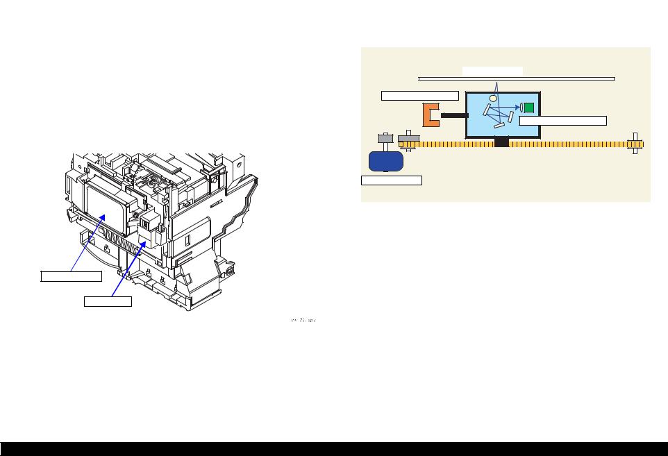
2.2.2 Scanner Mechanism
The scanner consists of the Scanner Carriage Unit comprising the CCD for capturing images and the light source for illuminating the document, the Scanner Motor and Timing Belt for moving the scanner carriage unit along the document surface, and the Scan HP Detector for detecting the position of the scanner carriage unit.
Document
Scanner HP Detector
Scanner Carriage Unit
Scanner Motor
Figure 2-3. Scanner Mechanism
Operating Principles |
Mechanism |
16 |
EPSON Stylus PHOTO RX600/610, RX620/630 |
Revision C |
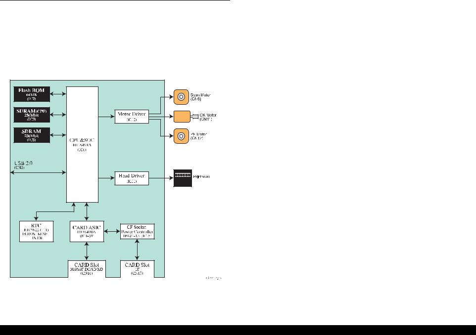
2.3 Electric Circuit
The electric circuit boards of Stylus PHOTO RX600/610, RX620/630 are as follows:
C543MAIN Board (main circuit board)
C543PSB Board / C543PSE Board (power supply circuit board)
CCD circuit board (Scanner circuit board)
Panel circuit board
Figure 2-4. Electric Circuit Block
Operating Principles |
Electric Circuit |
17 |

EPSON Stylus PHOTO RX600/610, RX620/630 |
Revision C |
2.3.1 C543 Main Circuit Board
2.3.1.1 Feature
USB 2.0 with multi-end points allows high speed SPC without HUB
SOC with printer control, scanner control, PT control, CPU SuperMacro
1CPU (NA85E2C by NEC) controls printer, scanner and PT unit
256Mbit*16 SDRAM (2 units)
A6615 drives DC x 2 and DC x 2 with 1Chip to motor driver
SOC obtains wider band ranges by setting action frequency of local SDRAM to 96MHz
Copy function allows faster process with SOC to scan, and to generate 2- values, microwave, image buffer instead of going through CPU bus.
Equipped with a color LCD (2.5-inch DTFD liquid crystal display) as standard.
Low current allows LCD to reduce power consumption in low power mode as follows:
•Lowering power supply voltage
•Shutting off optical current for optical sensor
•SLEEP mode for motor drive
•Saving the power for printer with no exciting motor
•Saving the power for scanner by turning off the lamp
•Equipped with printer tray open sensor
|
|
|
Table 2-4. |
|
|
|
|
|
|
Main Element |
location |
|
Function |
|
|
|
|
|
|
|
|
• Built-in NA85E2C core |
|
|
|
|
• Built-in iLB RAM 12Kbyte, Built-in dLB RAM 4Kbyte |
||
|
|
|
Built-in iCACHE 8Kbyte, Built-in dCACHE 8Kbyte |
|
|
|
• |
Action frequency |
|
Built-in CPU core |
|
|
CPU core |
:192MHz(SSCG) |
SOC |
IC6 |
|
NPB macro (UART, TimerC/D, Prescaler) |
:48MHz |
(E01A49B*) |
|
|
User logic (scanner/photo print) |
:48MHz (SSCG) |
|
|
|
User logic (printer) |
:48MHz |
|
|
|
Local SDRAM |
:96MHz(SSCG) |
|
|
|
External bus clock |
:64MHz(SSCG) |
|
|
• |
Power supply voltage : internal 1.5 V, external 3.3 V |
|
|
|
|
|
|
FLASH ROM |
IC2 |
• Firmware |
|
|
(MBM29PL64LM) |
• 64MB, 16bit bus, 48pin, 3.3V drive |
|
||
|
|
|||
SDRAM |
|
• System Memory (for CPU) |
|
|
(K4S561632) |
|
• 256 Mbit, 16 bit bus, 54pin, 133MHz (CL=2) minimum |
||
|
|
|
||
SDRAM |
|
• Work memory for copy function (image processing) |
||
(K4S561632) |
|
• 256 Mbit, 16 bit bus, 54pin, 133MHz (CL=2) minimum |
||
Card ASIC |
IC14 |
• Bus clock : 64MHz , internal clock : 48MHz |
|
|
(E09A49B*) |
• 3.3V Single power supply |
|
||
|
|
|||
|
|
|
|
|
CF Socket Power |
|
• 8 pin PSOP |
|
|
Controller |
IC15 |
• |
Power control 1CH with current limit |
|
(TPS2041A) |
|
|
|
|
|
|
Multiple IC |
|
|
RTC circuit |
IC1 |
• |
EEPROM ( Default value, store various parameters) |
|
(RTC9822) |
• RESET |
|
||
|
|
|||
|
|
• TIMER |
|
|
|
|
|
|
|
Motor drive circuit |
IC12 |
• |
CR motor, PF motor, scanner motor drive circuit |
|
(A6615) |
• Drive motor: 42V ±5% |
|
||
|
|
|||
Head drive circuit |
IC11 |
• |
Head drive control (control port for SOC) |
|
(E09A41RA) |
|
|
|
|
|
|
|
|
|
|
|
|
|
|
Operating Principles |
Electric Circuit |
18 |

C H3A P T E R
TROUBLESHOOTING

EPSON Stylus PHOTO RX600/610, RX620/630 |
Revision C |
3.1 Overview
With this printer, almost all troubles can be coped with by using “EPSON Status Monitor 3” installed on the host personal computer.
Once an error occurs, the “EPSON Status Monitor 3” will appear as a pop-up window on the screen of the host PC. It will show details of how to cope with the trouble. In almost all cases, the user can recover the printer from the error, provided that the user follows the instructions indicated on the pop-up window.
In addition, the User's Manual for EPSON Stylus PHOTO RX600/610, RX620/630 describes detailed steps to be taken for recovery from typical errors.
3.1.1 Specified Tools
This printer does not require any specified tools for troubleshooting.
3.1.2 Preliminary Checks
Before starting troubleshooting, be sure to verify that the following conditions are all met:
The power supply voltage must be within the specification limits. (Measure the voltage at the wall socket.)
The POWER CORD must be free from damage, short circuit or breakage, or miswiring in the POWER CORD.
The printer must be grounded properly.
The printer should not be located in a place where it can be exposed to too high or low temperature, too high or low humidity, or abrupt temperature change.
The printer should not be located near waterworks, near humidifiers, near heaters or near flames, in a dusty atmosphere or in a place where the printer can be exposed to blast from an air conditioner.
The printer should not be located in a place where volatile or inflammable gases are produced.
The printer should not be located in a place where it can be exposed to direct rays of the sun.
The printer must be located in a well-ventilated place.
The printer must be placed on a strong and steady level table (without an inclination larger than 5 degrees).
The paper used must conform to the specification.
There is no error in handling of the printer.
Check the inside of the printer, and remove foreign matters, if any, such as paper clips, staples, bits of paper, paper dust or toner.
Clean the inside of the printer and the rubber rolls.
Troubleshooting |
Overview |
20 |
EPSON Stylus PHOTO RX600/610, RX620/630 |
Revision C |
3.2 Troubleshooting at Unit Level
By following this troubleshooting procedure, when some trouble has occurred, you can easily identify the unit which is the cause of the trouble, from its observation. Table 3-1 and Table 3-2 list the observations of various troubles. Once the type of the trouble has been identified, refer to the flowchart for that trouble.
The flowchart shown in Table 3-1 outlines the troubleshooting procedure.
NOTE: See “3.6 Troubleshooting for Motors and Sensors” (p35) for troubleshooting for motors and sensors.
Identifying the Trouble
Table 3-1, “LCD Indication”
Table 3-2, “Observations and Troubleshooting Flowcharts”
|
|
|
|
|
|
|
|
|
|
|
|
|
|
|
|
|
|
|
|
|
|
|
|
|
|
|
|
|
|
|
|
|
|
|
|
|
|
|
|
|
|
|
|
|
|
|
|
|
|
Repair at Unit Level |
|
|
|
|
|
|
|
|
|
|
|
|
|
|
|
|
|
|
|
|
|
|
|
|
|
|
|
|
|
|
|
|
|||||||||||||||
|
|
|
|
Diagnosing the Following Units |
|
|
|
|
|
|
|
|
|
|||||||||||||||||||||||||||||||||||
|
|
|
|
|
|
|
|
|
|
|
|
|
|
|
|
|
|
|
|
|
|
|
|
|
|
|
|
|
|
|
|
|
|
|
|
|
|
|
|
|
|
|
|
|
|
|
|
|
|
|
|
|
|
|
|
|
|
|
|
|
|
|
|
|
|
|
|
|
|
|
|
|
|
|
|
|
|
|
|
|
|
|
|
|
|
|
|
|
|
|
|
|
|
|
|
|
|
|
|
|
|
|
|
|
|
|
|
|
|
|
|
|
|
|
|
|
|
|
|
|
|
|
|
|
|
|
|
|
|
|
|
|
|
|
|
|
|
|
|
|
|
|
|
|
|
|
Repair at Parts
Level
Printer Mechanism |
Scanner Mechanism |
Motor and Sensor Repair |
|
Disassembly = Chapter 4
Adjustment = Chapter 5
Figure 3-1. Troubleshooting Flowchart
Table 3-1. LCD Indication
|
LCD Indication |
LED Indication |
||
Error Status |
EMC |
EAI |
Power |
Error |
|
LED |
|||
|
|
|
|
|
Fatal error in |
Printer error occurred. |
Printer error occurred. |
|
Lighting |
printer |
Please see the |
Please see the User’s Guide. |
- |
|
|
documentation. |
|
|
up |
|
|
|
|
|
|
|
|
|
|
Fatal error in |
Scanner error occurred. |
Scanner error occurred. |
|
Lighting |
scanner |
Please see the |
Please see the User’s Guide. |
- |
|
|
documentation. |
|
|
up |
|
|
|
|
|
Scanner unit |
Scanner unit open. Please close the scanner unit. |
- |
Lighting |
|
is open |
|
|
|
up |
Paper out in |
Paper out or feed error. |
Paper out or feed error. |
|
Lighting |
printer |
Please insert paper or clear |
Please insert paper or clear |
- |
|
|
the paper feed error, then |
the paper feed error, then |
|
up |
|
press the Color button. |
press the Color button. |
|
|
Paper jam |
Paper jam. Press the color |
Paper jam. Press the color |
|
|
|
button or Load/Eject button. |
button or Load/Eject button. |
|
Lighting |
|
If the error is not cleared, |
If the error is not cleared, |
- |
|
|
please manually clear the |
please manually clear the |
|
up |
|
|
|
||
|
jam. |
jam. |
|
|
|
|
|
|
|
No ink |
No cyan ink cartridge. Press |
No cyan ink cartridge. Press |
|
Lighting |
cartridge |
the OK button to install a |
the OK button to install a |
- |
|
|
new ink cartridge. |
new ink cartridge. |
|
up |
|
|
|
||
Ink out |
Black ink out. Press the OK |
Black ink out. Press the OK |
|
Lighting |
|
button to replace the |
button to replace the |
- |
|
|
cartridge. |
cartridge. |
|
up |
|
|
|
||
|
|
|
|
|
Ink cartridge |
Ink cartridge(s) cannot be |
Ink cartridge(s) cannot be |
|
Lighting |
error |
found. Please insert ink |
found. Please insert ink |
- |
|
|
cartridge(s) and press the |
cartridge(s) and press the |
|
up |
|
OK button to continue. |
OK button to continue. |
|
|
|
|
|
|
|
Troubleshooting |
Troubleshooting at Unit Level |
21 |
EPSON Stylus PHOTO RX600/610, RX620/630 |
Revision C |
Table 3-2. Observations and Troubleshooting Flowcharts
Observation |
Details |
Refer to |
|
Power is on but not |
• LED does not turn on at all. |
|
|
operating |
• Printer mechanism does not operate at all. |
Figure 3-2 |
|
|
• Scanner mechanism does not operate at all. |
|
|
|
|
|
|
Error is detected |
• LCD/LED panel shows error status. |
Figure 3-3 |
|
Trouble related to |
• Printing is not done. |
|
|
• Print is abnormal (Dot missing, etc.). |
Figure 3-4 |
||
|
• Print quality is bad. |
|
|
|
|
|
|
Paper feeding is not |
• Paper feeding is not done. |
|
|
normally carried out. |
• Paper jam occurs. |
Figure 3-5 |
|
|
• Paper start up position is not correct. |
|
|
|
|
|
|
Faulty operation |
• Pressing a button does not work. |
Figure 3-6 |
|
panel |
|
||
|
|
||
|
|
|
|
Trouble related to |
• Scanner does not operate normally. |
Refer to “3.4 |
|
scanner |
|
Troubleshooting for |
|
|
|
Scanner” (p32) |
|
|
|
|
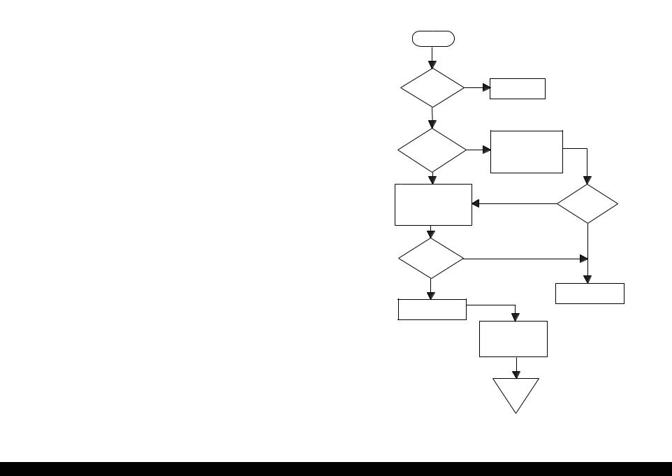
3.2.1Printer / Scanner does not operate at all even with power turned on
Start
AC power / |
No |
voltage |
|
is normal? |
|
Yes
Yes
Fuse (F1) of Fuse (F1) of power power board is board is blown? blown?
Input normal power..
Replace fuse. Disconnect CN3CN10of main board and turn power on again.
No
No
Check output voltage of
power board CN2. Fuse is blown again?
Yes
No
Power board output voltage is normal?
Yes
Replace power board
Replace main board
Check motors, head and other parts
End
Figure 3-2. Flowchart-1
Troubleshooting |
Troubleshooting at Unit Level |
22 |

EPSON Stylus PHOTO RX600/610, RX620/630 |
Revision C |
3.2.2 Error is detected |
3.2.3 Trouble related to Print |
|
|
|
|
Start |
|
|
|
|
Start |
|
|
|
|
|
|
|
|
|
|
|
|
Execute test printing |
|
|
|
|
Check error contents by |
|
|
|
|
|
|
|
|
LCD (See Table 3-1). |
|
|
|
|
|
|
|
|
|
|
|
|
No |
|
|
|
|
Yes |
|
|
|
Printing was |
|
|
|
|
|
|
|
successfully |
|
|
|
|
|
|
|
Turn power off, unlock |
|
done? |
|
|
|
|
|
|
|
Yes |
|
|
|
|
|
Printer error? |
|
CR and move CR with |
|
|
|
All the |
Yes |
|
|
|
hand. |
|
Yes |
|
|
||
|
|
|
|
|
|
cables are connected |
|
|
No |
|
|
|
Execute print |
|
properly to main |
|
|
|
|
|
|
board? |
|
|||
|
|
|
No |
quality is |
adjustment (Refer to |
|
|
|
|
|
|
normal? |
|
No |
|
||
Yes |
|
|
“Adjustment” on |
|
|
|||
Replace Ink cartridge |
CR cartridge can |
No |
page 63) |
|
|
|
||
Ink cartridge out |
|
with a new one by |
move smoothly? |
|
|
Connect correctly |
|
|
|
operation panel. |
|
|
|
|
|
||
error? |
|
|
Yes |
Execute cleaning |
|
|
|
|
No |
|
|
|
|
|
No |
||
|
|
|
|
|
|
|||
|
|
|
|
No |
|
|
||
|
|
|
Check CR motor and if |
|
|
Problem is |
Refer to Table 3-12 |
|
Maintenance error |
No |
|
Problem is |
Replace Ink cartridge |
solved? |
|||
Ink cartridge |
there is no problem, |
|
|
|||||
|
|
replace main board. |
solved? |
and execute test print. |
|
|
||
|
|
out error is |
|
|
|
|
Yes |
|
|
|
cleared? |
|
Yes |
|
|
|
|
|
|
|
|
|
|
No |
||
|
|
|
|
|
|
|
||
|
|
|
|
|
|
|
|
|
Replace waste ink porous |
|
Yes |
|
|
Yes |
|
|
Problem is |
pad and reset counter. |
|
Yes |
|
|
|
solved? |
||
(Refer to “Disassembly and |
|
|
Carriage smoothly |
|
Problem is |
|
|
|
Assembly” on page 36 and |
|
|
|
solved? |
|
|
Yes |
|
|
|
moves? |
|
|
|
|
||
“Adjustment” on page 63) |
|
|
|
|
No |
|
|
|
|
|
|
No |
|
|
|
|
|
|
|
|
|
|
|
|
|
|
Check whether Head |
|
|
Refer to Table 3-12 |
|
Replace main board |
|||
Refer to Table 3-12 |
|
|
|
|||||
FFC is connected |
|
|
|
|
||||
|
|
|
|
|
|
|||
properly to head. |
|
|
|
|
|
|
|
|
|
|
|
|
|
Yes |
No |
|
|
|
|
|
|
|
Problem is |
|
|
|
|
|
|
|
|
solved? |
|
|
|
|
|
End |
End |
End |
|
End |
|
End |
|
|
|
|
|
|
|||
Figure 3-3. Flowchart-2 |
Figure 3-4. Flowchart-3 |
Troubleshooting |
Troubleshooting at Unit Level |
23 |

EPSON Stylus PHOTO RX600/610, RX620/630 |
Revision C |
3.2.4 Paper feeding is not normally carried out
Start
No
Paper is correctly set in ASF?
Set paper correctly.
Yes
No
Paper loading roller and PF roller are correctly rotating?
Yes
Remove foreign matters, if any, from paper route.
Clean rollers on paper route. (Refer to “Maintenance” on page 80)
No
PF motor is driving?
Yes
Check whether connector of PF motor is connected to CN6 of main board. If it is connected properly, replace main board.
Problem is |
No |
|
|
solved? |
|
Yes |
Refer to Table 3-12 |
End |
End |
Figure 3-5. Flowchart-4
3.2.5 Operation Panel faulty
Start
Operation Panel is connected
properly with No cable?
Yes
Connectcorrectly Operation panel again.
Yes
Problem is solved?
No
Replace operation panel.
No
Problem is solved?
Yes |
|
Replace main |
|
|
|
board. |
|
|
|
|
|
|
|
|
|
|
|
|
|
End |
End |
Figure 3-6. Flowchart-5
Troubleshooting |
Troubleshooting at Unit Level |
24 |

EPSON Stylus PHOTO RX600/610, RX620/630 |
Revision C |
3.3 Troubleshooting for Printer
This section describes repair / service of the Printer Mechanism. Listed below are various problems which may occur, observations of such problems, check point and remedies. For the pertinent observation, check the functions of the parts in question according to Check Point.
Table 3-3. Printer Errors
Observation |
Cause |
Remedy |
Ink shortage / |
• If any ink cartridge comes |
• Start cleaning execution command on |
Ink out |
close to Ink out, Printer |
Panel or by Utility. |
|
continues printing in ink |
• Carriage automatically moves to |
|
shortage status. |
replacement position. |
|
• If cartridge is completely |
• Replace ink cartridge with a new one. |
|
empty, Printer indicates ink |
|
|
out error and stop printing. |
|
|
|
|
Paper out |
• When Printer cannot load |
1.Set paper on tray if paper is out. |
|
paper, paper out error is |
2.If paper is stopped midway, pull paper |
|
indicated. |
out and check that paper is not folded. |
|
• Paper stops in front of PE |
Loosen paper well and set it again with |
|
detector or paper is not loaded. |
edge guide adjusted to paper width. |
|
• Paper is loaded without |
3.Execute “Load/Eject”. |
|
adjusting paper to right edge |
• Clean paper loading roller. Or replace |
|
guide. |
paper loading roller. |
|
|
• Check that gears for ASF are engaged |
|
|
correctly. |
Paper jam |
When paper is not ejected, |
• Select “Load/Eject” from menu and |
|
paper jam error is indicated. |
execute it. |
|
|
1.Open the printer cover and remove with |
|
|
hand all the paper inside the printer and |
|
|
all the set paper if there is paper on the |
|
|
way of loading. |
|
|
2.Check that there is no paper in the printer |
|
|
and set paper again and execute paper |
|
|
loading and paper ejection. Then, this |
|
|
error display will be cleared and if there |
|
|
is print data, print operation will start. |
|
|
• Check whether Platen gap is correct |
|
|
value. (Refer to “Adjustment” on |
|
|
page -63) |
|
|
|
Table 3-3. Printer Errors (continued)
Observation |
Cause |
Remedy |
Ink cartridge out |
• If Ink cartridge is not correctly |
• Check CSIC connection circuit. |
|
set, printer indicates ink |
• Replace ink cartridge. |
|
cartridge out error. |
|
Maintenance |
Waste ink overflow indication |
After replacing waste ink porous pad, |
error |
is displayed if the total amount |
reset waste ink overflow counter. |
|
of ink consumed by cleaning |
|
|
and/or flushing has exceeded |
|
|
the predetermined limit. |
|
|
|
|
Fatal error |
• Carriage error: |
• Several seconds or more after turning |
|
• Home of carriage can not be |
power off, press power switch to turn |
|
recognized. |
power on. |
|
• Abnormal external power was |
• Open maintenance cover and check that |
|
applied to carriage or carriage |
there is no obstacle in the carriage |
|
operation is obstructed during |
moving zone. |
|
printing. |
If the error is not cleared even by the above |
|
• PF error: |
operation, check the followings: |
|
PF motor does not operate |
• CR HP sensor/Harness |
|
adequately to feed paper by the |
• CR Lock mechanism |
|
required distance. |
• Main board |
|
|
|
Troubleshooting |
Troubleshooting for Printer |
25 |

EPSON Stylus PHOTO RX600/610, RX620/630 |
Revision C |
Troubleshooting without error display on LCD. For Items and pages, refer the following:
•Faulty pump mechanism (p26)
•Ink is not absorbed at all or ink absorption is poor. (p26)
•Faulty carriage operation (p27)
•Printing is not carried out correctly. (p27)
•Faulty print (p28)
•Faulty paper loading (p30)
•Faulty paper ejection (p30)
•Printer stops during initialization (p31)
Faulty pump mechanism
Table 3-4. Diagnostics when pump mechanism is abnormal
Condition |
Cause |
Check Point |
Remedy |
|
When power is turned on, PF |
There are foreign matters on the PF |
Operate the platen drive gear by hand and check whether it |
|
Remove foreign matters. |
motor operation is abnormal. |
gear. |
rotates properly. |
Replace the printer mechanism. |
|
|
|
|
|
|
|
PF motor is faulty. |
Check whether the internal coil resistance is just as specified |
Replace the printer mechanism or PF motor. |
|
|
|
and whether the harness is connected properly. See Table 3-21 |
|
|
|
|
“Motor Resistance and Check Point” (p 35). |
|
|
|
|
|
|
|
Ink is not absorbed at all or ink absorption is poor.
Table 3-5. Diagnostics when ink is not absorbed
Condition |
Cause |
Check Point |
Remedy |
|
Ejected ink does not flow into |
Pump tube is crashed. |
Check tube with the naked eye. |
Replace the printer mechanism or pump unit. |
|
Ink Eject tube. |
|
|
|
|
Capping unit is faulty. |
Check capping rubber with the naked eye. |
Replace the printer mechanism or capping unit. |
||
|
||||
|
Tube is projecting from cap. |
Check with the naked eye whether tube is projecting from cap. |
Connect the tube correctly. |
|
|
|
|
|
|
|
Pump tube is entangled in the pump |
When cap assembly slides up completely, check whether there |
Remove the entangled pump tube carefully, correct the tube |
|
|
unit. |
is a small slack in pump tube between cap assembly and pump |
condition and connect it to the cap assembly. |
|
|
|
unit. |
|
|
Ink is not absorbed from head |
Dirt on cap |
Check whether any foreign matter is adhering to cap. |
Remove foreign matters from the cap and if the cap is |
|
to cap. |
|
|
damaged, replace it with a new one. |
|
|
|
|
|
|
|
Faulty slide-up of cap |
Check whether two compression springs are set on cap |
Set the compression springs on the cap assembly. |
|
|
|
assembly. |
|
|
|
|
|
|
Troubleshooting |
Troubleshooting for Printer |
26 |

EPSON Stylus PHOTO RX600/610, RX620/630 |
|
Revision C |
||
Faulty carriage operation |
|
|
|
|
|
|
Table 3-6. Diagnostics when carriage action is abnormal |
|
|
|
|
|
|
|
Condition |
Cause |
Check Point |
Remedy |
|
|
|
|
|
|
When power is turned on, |
|
There is an obstacle in CR shift area. |
Check with the naked eye whether there is an obstacle. |
Remove the obstacle. |
carriage operation is |
|
|
|
|
|
CR lock is not released. |
Check that change lever is in the front of printer. |
Return the change lever to the back of printer by tweeters or a |
|
abnormal. |
|
|||
|
|
|
small driver. |
|
|
|
|
|
|
|
|
|
Check whether the CN12 connector and coil resistance of the |
Connect the PF motor to CN12 on the main board. |
|
|
|
PF motor are as specified. See Table 3-21 “Motor Resistance |
Replace the printer mechanism or PF motor. |
|
|
|
and Check Point” (p 35). |
|
|
|
|
Check whether any gear is damaged on the torque |
Replace the damaged gear with a new one. |
|
|
|
transmission route of PF motor. |
|
|
|
Faulty CR motor |
Check whether the internal coil resistance is just as specified |
Replace the CR motor. |
|
|
|
and whether the harness is connected properly. See Table 3-21 |
|
|
|
|
“Motor Resistance and Check Point” (p 35). |
|
|
|
|
|
|
Abnormal carriage operation |
|
Carriage does not move smoothly. |
Operate the carriage by hand and check whether carriage |
Clean the CR guide shaft and lubricate. |
during printing |
|
|
moves smoothly. |
|
|
|
|
Check tension of timing belt. |
Adjust tension or replace the belt. |
|
|
|
|
|
|
|
|
Check whether there is an obstacle in carriage route. |
Remove the obstacle. |
|
|
|
|
|
Printing is not carried out correctly.
Table 3-7. Diagnostics when printing is erratic
Condition |
Cause |
Check Point |
Remedy |
Carriage moves correctly but |
Head FFC is not connected properly. |
Check whether Head FFC is connected properly to CN13 and |
Connect the FFC correctly. |
printing is not normal. |
|
CN14 of main board. |
|
|
|
|
|
|
Inside of FFC is not connected |
Check FFC by tester. |
Replace the FFC. |
|
properly. |
|
|
|
Faulty ink cartridge |
Set new ink cartridge and execute test printing. |
Replace the ink cartridge. |
|
|
|
|
|
Faulty head unit |
Repeat cleaning and test printing alternately several times. |
Replace the head unit. |
|
Faulty head cleaner |
Check whether dust is adhering to head cleaner. |
Clean or replace the head cleaner. |
|
|
|
|
Troubleshooting |
Troubleshooting for Printer |
27 |

EPSON Stylus PHOTO RX600/610, RX620/630 |
|
Revision C |
|
Faulty print |
|
|
|
|
Table 3-8. Diagnostics when printing is abnormal |
|
|
|
|
|
|
Condition |
Cause |
Check Point |
Remedy |
|
|
|
|
Faulty printing occurs at |
Head surface is dirty. |
Repeat cleaning and test printing alternately several times. |
Clean with a swab fixed to a stick. |
specific dots. |
(Dot missing occurs) |
|
|
|
|
|
|
|
Faulty head FFC |
Check whether head FFC is damaged. |
Replace the head FFC with a new one. |
|
Faulty head unit |
Repeat cleaning and nozzle checking alternately several |
If the condition is not improved even after cleaning, replace |
|
|
times. |
the head. |
|
|
|
|
|
Capping porous pad is in contact with |
Check capping porous pad with the naked eye. |
Replace the capping porous pad, if its shape is deformed or it |
|
head surface. |
|
is damaged. |
Sometimes dots are missing. |
Head surface is dirty. |
Repeat cleaning and nozzle checking alternately several |
Clean with a swab fixed to a stick. |
|
(Dot is missing occurs) |
times. |
|
|
|
|
|
|
Inside of FFC is not connected |
Check FFC by tester. |
Replace the head FFC. |
|
properly. |
|
|
|
Head FFC is not connected. |
Check whether Board and Carriage FFC are connected. |
Connect the FFC correctly. |
|
|
|
|
|
Faulty Head unit. |
Execute cleaning several times, and Check nozzle. |
If the condition is not improved even after cleaning, replace |
|
|
|
the head. |
|
Faulty ink cartridge. |
Set new ink cartridge and check nozzle. |
Replace the ink cartridge. |
|
|
|
|
Black points or dots are |
Head FFC is not connected. |
Check whether Board and Carriage FFC are connected. |
Connect the FFC correctly. |
printed. |
Faulty head unit |
Check connection with head FFC. |
If connection with the FFC is not faulty, replace the head. |
|
|||
Vertical line is not straightly |
Bi-D adjustment has not been made. |
Make Bi-D adjustment. |
Refer to “ Adjustment” (p63) |
lined. |
|
|
|
|
|
|
|
Troubleshooting |
Troubleshooting for Printer |
28 |

EPSON Stylus PHOTO RX600/610, RX620/630 |
Revision C |
Table 3-8. Diagnostics when printing is abnormal (continued)
Condition |
Cause |
Check Point |
Remedy |
White line appears in output |
Dirt is adhering to CR guide shaft. |
Check whether dirt is adhering to the surface of CR guide |
Clean the surface of CR guide shaft with a dry and soft cloth. |
data. |
|
shaft. |
|
|
|
|
|
|
Faulty CR guide shaft. |
Check that CR guide shaft is steadily installed in the |
Reinstall the CR guide shaft on the mounting slats (wing |
|
|
designated position. |
boards) on both sides of the frame, and fix it with the rod |
|
|
Check that CR guide shaft surface is flat. |
spring. |
|
|
|
Replace the CR guide shaft with a new one. |
|
Faulty slide operation of Carriage. |
Check whether sufficient oil is remaining on the surface in the |
Clean the surface in the carriage slide area and apply a |
|
|
carriage slide area on the Paper Eject Frame. |
specified amount of G-26. Refer to “ Maintenance” (p80) |
|
|
|
|
|
Paper feeding route is dirty. |
Check whether PF roller is dirty. |
Clean the surface of the PF roller carefully with a soft brush. |
|
Damaged gear |
Check whether the following parts are not damaged. |
Replace the damaged part with a new one. |
|
|
• Combination gear16, 21.6 |
|
|
|
• Combination gear 11.6, 36.8 |
|
|
|
• Spur gear 73.6 |
|
|
|
• Spur gear 25.6 |
|
|
|
|
|
|
Platen gap is not correct. |
Adjust platen gap. |
Refer to “ Adjustment” (p63) |
|
As head surface is dirty, dot jet |
Repeat cleaning and test printing alternately several times. |
Clean with a swab fixed to a stick. |
|
direction is slanting. |
|
|
|
Check whether dust is adhering to head cleaner. |
Clean or replace the head cleaner. |
|
|
|
||
|
Faulty ink cartridge |
Set new ink cartridge and execute test printing. |
Replace the ink cartridge. |
|
|
|
|
|
Faulty head unit |
Clean several times, and execute test printing. |
Replace the head unit. |
|
|
|
|
Troubleshooting |
Troubleshooting for Printer |
29 |
Loading...