


 Loading...
SERVICE MANUAL
Color Inkjet Printer
Stylus Photo RX680/RX685/RX690
SEMF07008
|
PRECAUTIONS |
Precautionary notations throughout the text are categorized relative to 1) Personal injury and 2) damage to equipment. |
|
DANGER |
Signals a precaution which, if ignored, could result in serious or fatal personal injury. Great caution should be exercised in performing procedures preceded by |
|
DANGER Headings. |
WARNING |
Signals a precaution which, if ignored, could result in damage to equipment. |
The precautionary measures itemized below should always be observed when performing repair/maintenance procedures.
DANGER
1.ALWAYS DISCONNECT THE PRODUCT FROM THE POWER SOURCE AND PERIPHERAL DEVICES PERFORMING ANY MAINTENANCE OR REPAIR PROCEDURES.
2.NO WORK SHOULD BE PERFORMED ON THE UNIT BY PERSONS UNFAMILIAR WITH BASIC SAFETY MEASURES AS DICTATED FOR ALL ELECTRONICS TECHNICIANS IN THEIR LINE OF WORK.
3.WHEN PERFORMING TESTING AS DICTATED WITHIN THIS MANUAL, DO NOT CONNECT THE UNIT TO A POWER SOURCE UNTIL INSTRUCTED TO DO SO. WHEN THE POWER SUPPLY CABLE MUST BE CONNECTED, USE EXTREME CAUTION IN WORKING ON POWER SUPPLY AND OTHER ELECTRONIC COMPONENTS.
4.WHEN DISASSEMBLING OR ASSEMBLING A PRODUCT, MAKE SURE TO WEAR GLOVES TO AVOID INJURIER FROM METAL PARTS WITH SHARP EDGES.
WARNING
1.REPAIRS ON EPSON PRODUCT SHOULD BE PERFORMED ONLY BY AN EPSON CERTIFIED REPAIR TECHNICIAN.
2.MAKE CERTAIN THAT THE SOURCE VOLTAGES IS THE SAME AS THE RATED VOLTAGE, LISTED ON THE SERIAL NUMBER/RATING PLATE. IF THE EPSON PRODUCT HAS A PRIMARY AC RATING DIFFERENT FROM AVAILABLE POWER SOURCE, DO NOT CONNECT IT TO THE POWER SOURCE.
3.ALWAYS VERIFY THAT THE EPSON PRODUCT HAS BEEN DISCONNECTED FROM THE POWER SOURCE BEFORE REMOVING OR REPLACING PRINTED CIRCUIT BOARDS AND/OR INDIVIDUAL CHIPS.
4.IN ORDER TO PROTECT SENSITIVE MICROPROCESSORS AND CIRCUITRY, USE STATIC DISCHARGE EQUIPMENT, SUCH AS ANTI-STATIC WRIST STRAPS, WHEN ACCESSING INTERNAL COMPONENTS.
5.REPLACE MALFUNCTIONING COMPONENTS ONLY WITH THOSE COMPONENTS BY THE MANUFACTURE; INTRODUCTION OF SECOND-SOURCE ICs OR OTHER NON-APPROVED COMPONENTS MAY DAMAGE THE PRODUCT AND VOID ANY APPLICABLE EPSON WARRANTY.
6.WHEN USING COMPRESSED AIR PRODUCTS; SUCH AS AIR DUSTER, FOR CLEANING DURING REPAIR AND MAINTENANCE, THE USE OF SUCH PRODUCTS CONTAINING FLAMMABLE GAS IS PROHIBITED.

About This Manual
This manual describes basic functions, theory of electrical and mechanical operations, maintenance and repair procedures of the printer. The instructions and procedures included herein are intended for the experienced repair technicians, and attention should be given to the precautions on the preceding page.
Manual Configuration
This manual consists of six chapters and Appendix.
CHAPTER 1.PRODUCT DESCRIPTIONS
Provides a general overview and specifications of the product.
CHAPTER 2.OPERATING PRINCIPLES
Describes the theory of electrical and mechanical operations of the product.
CHAPTER 3.TROUBLESHOOTING
Describes the step-by-step procedures for the troubleshooting.
CHAPTER 4.DISASSEMBLY / ASSEMBLY
Describes the step-by-step procedures for disassembling and assembling the product.
CHAPTER 5.ADJUSTMENT
Provides Epson-approved methods for adjustment.
CHAPTER 6.MAINTENANCE
Provides preventive maintenance procedures and the lists of Epsonapproved lubricants and adhesives required for servicing the product.
APPENDIX Provides the following additional information for reference:
• Electrical circuit boards schematics
Symbols Used in this Manual
Various symbols are used throughout this manual either to provide additional information on a specific topic or to warn of possible danger present during a procedure or an action. Be aware of all symbols when they are used, and always read NOTE, CAUTION, or WARNING messages.
ADJUSTMENT |
Indicates an operating or maintenance procedure, practice or condition |
|
REQUIRED |
that is necessary to keep the product’s quality. |
|
CAUTION |
Indicates an operating or maintenance procedure, practice, or condition |
|
that, if not strictly observed, could result in damage to, or destruction of, |
||
|
||
|
equipment. |
|
CHECK |
May indicate an operating or maintenance procedure, practice or |
|
POINT |
condition that is necessary to accomplish a task efficiently. It may also |
|
|
provide additional information that is related to a specific subject, or |
|
|
comment on the results achieved through a previous action. |
|
WARNING |
Indicates an operating or maintenance procedure, practice or condition |
|
that, if not strictly observed, could result in injury or loss of life. |
||
|
REASSEMBLY Indicates that a particular task must be carried out according to a certain standard after disassembly and before re-assembly, otherwise the qual-
ity of the components in question may be adversely affected.

|
|
Revision Status |
|
|
|
Revision |
Date of Issue |
Description |
A |
August 3, 2007 |
First Release |
|
|
|

EPSON Stylus Photo RX680/RX685/RX690 |
Revision A |
CONTENTS
Chapter 1 PRODUCT DESCRIPTION
1.1 |
Features............................................................................................................... |
10 |
|
1.2 |
Printing Specifications........................................................................................ |
11 |
|
|
1.2.1 |
Basic Specifications................................................................................. |
11 |
|
1.2.2 |
Ink Cartridge............................................................................................ |
11 |
|
1.2.3 |
Print Mode ............................................................................................... |
12 |
|
1.2.4 |
Supported Paper....................................................................................... |
13 |
|
1.2.5 |
Printing Area ........................................................................................... |
16 |
1.3 |
Scanner Specifications........................................................................................ |
16 |
|
1.4 |
General Specifications........................................................................................ |
17 |
|
|
1.4.1 |
Electrical Specifications .......................................................................... |
17 |
|
1.4.2 |
Safety Approvals (Safety standards/EMI)............................................... |
17 |
|
1.4.3 |
Acoustic Noise......................................................................................... |
17 |
|
1.4.4 |
Durability................................................................................................. |
17 |
|
1.4.5 |
Environmental Conditions....................................................................... |
18 |
1.5 |
Interface.............................................................................................................. |
18 |
|
|
1.5.1 |
USB Interfaces......................................................................................... |
18 |
|
1.5.2 Memory Card Slots.................................................................................. |
19 |
|
1.6 |
Control Panel ...................................................................................................... |
20 |
|
|
1.6.1 Operation Buttons & LED....................................................................... |
20 |
|
1.7 |
Specifications of Each Function......................................................................... |
21 |
|
|
1.7.1 |
Stand-alone Copy Function ..................................................................... |
21 |
|
1.7.2 |
Memory Card Direct Print Function........................................................ |
21 |
|
1.7.3 |
Backup Function...................................................................................... |
22 |
|
1.7.4 |
Camera Direct Print Function (USB Direct Print/PictBridge) ................ |
23 |
|
1.7.5 |
Speciality Print Functions........................................................................ |
23 |
|
1.7.6 Setup Mode.............................................................................................. |
23 |
|
Chapter 2 OPERATING PRINCIPLES
2.1 |
Overview ............................................................................................................ |
26 |
|
2.1.1 Printer Mechanism .................................................................................. |
26 |
|
2.1.2 Motors and Sensors ................................................................................. |
26 |
2.2 |
Printer Mechanism Operating Principles ........................................................... |
28 |
|
2.2.1 Printhead.................................................................................................. |
28 |
|
2.2.2 Carriage Mechanism................................................................................ |
28 |
|
2.2.3 APG Mechanism ..................................................................................... |
30 |
|
2.2.4 Paper Loading/Feeding Mechanism........................................................ |
33 |
|
2.2.5 CD-R Mechanism.................................................................................... |
45 |
|
2.2.6 Ink System............................................................................................... |
49 |
|
2.2.7 Scanner Unit ............................................................................................ |
50 |
2.3 |
Electrical Circuits Operating Principles ............................................................. |
51 |
|
2.3.1 Features ................................................................................................... |
51 |
|
2.3.2 Circuit Board Components...................................................................... |
52 |
|
2.3.3 Main Board Circuit Block Diagram ........................................................ |
53 |
2.4 |
Banding Reduction System (BRS) / Paper Feed Amount Profile Correction (PFP) . 54 |
|
Chapter 3 TROUBLESHOOTING
3.1 |
Overview ............................................................................................................ |
56 |
|
|
3.1.1 |
Troubleshooting on Motors and Sensors................................................. |
56 |
3.2 |
Error/Warning Indications.................................................................................. |
57 |
|
|
3.2.1 |
List of Error Indications .......................................................................... |
57 |
3.3 |
Troubleshooting.................................................................................................. |
59 |
|
|
3.3.1 |
Troubleshooting with Error Indications .................................................. |
59 |
3.4 |
Troubleshooting by Symptom (no error indications) ......................................... |
78 |
|
|
3.4.1 |
Troubleshooting Printer Mechanism Problems....................................... |
78 |
|
3.4.2 |
Troubleshooting Electrical Problems ...................................................... |
81 |
|
3.4.3 |
Troubleshooting Ink Supply Problems.................................................... |
81 |
|
3.4.4 |
Troubleshooting I/F-related Problems..................................................... |
83 |
3.5 |
Troubleshooting for Scanner .............................................................................. |
84 |
|
3.6 |
Troubleshooting Duplex Unit Problems............................................................. |
86 |
|
6

EPSON Stylus Photo RX680/RX685/RX690 |
Revision A |
Chapter 4 DISASSEMBLY AND ASSEMBLY |
|
|
4.1 Overview ............................................................................................................ |
88 |
|
4.1.1 |
Precautions .............................................................................................. |
88 |
4.1.2 |
Tools ........................................................................................................ |
89 |
4.1.3 |
Screws...................................................................................................... |
89 |
4.1.4 Work Completion Checklist .................................................................... |
90 |
|
4.1.5 |
Required Preparation before Disassembly .............................................. |
91 |
4.1.6 |
Orientation Definition ............................................................................. |
91 |
4.1.7 How to Unlock the Carriage.................................................................... |
91 |
|
4.1.8 |
Disassembly Flowchart ........................................................................... |
92 |
4.2 Removing Exterior Parts/Components ............................................................... |
94 |
|
4.2.1 |
Paper Support Assy ................................................................................. |
94 |
4.2.2 Rear Cover/Automatic Duplex Unit........................................................ |
94 |
|
4.2.3 |
Cassette Assy........................................................................................... |
95 |
4.2.4 Front ASF Cover Assy ............................................................................ |
96 |
|
4.2.5 |
Panel Unit/Upper Housing ...................................................................... |
96 |
4.2.6 |
Scanner Unit .......................................................................................... |
100 |
4.2.7 Hinge Assy ............................................................................................ |
102 |
|
4.3 Disassembling the Scanner Unit....................................................................... |
103 |
|
4.3.1 Document Cover/ASF Cover ................................................................ |
103 |
|
4.3.2 Scanner Housing.................................................................................... |
103 |
|
4.3.3 |
CIS Unit................................................................................................. |
104 |
4.3.4 CR Motor Unit....................................................................................... |
105 |
|
4.4 Removing Control Boards................................................................................ |
106 |
|
4.4.1 Main Board Assy................................................................................... |
106 |
|
4.4.2 Disassembling the Main Board Assy .................................................... |
107 |
|
4.4.3 |
Disassembling the Panel Unit................................................................ |
108 |
4.5 Disassembling the Major Parts/Components.................................................... |
110 |
|
4.5.1 Middle Housing ..................................................................................... |
110 |
|
4.5.2 Power Supply Unit ................................................................................ |
113 |
|
4.5.3 |
Stacker Assy .......................................................................................... |
114 |
4.5.4 |
Printer Mechanism................................................................................. |
114 |
4.5.5 CR Scale ................................................................................................ |
117 |
|
4.5.6 |
Printhead................................................................................................ |
118 |
4.5.7 APG Assy/Sub Board/ASF Encoder/Retard ASF Assy ........................ |
120 |
|
4.5.8 |
Waste Ink Pads/Foot.............................................................................. |
123 |
4.5.9 EJ Frame Assy/CDR Guide Assy.......................................................... |
124 |
|
4.5.10 PF Encoder .......................................................................................... |
127 |
|
4.5.11 PF Motor.............................................................................................. |
128 |
|
4.5.12 CR Motor............................................................................................. |
129 |
|
4.5.13 |
Carriage Assy ...................................................................................... |
130 |
4.5.14 Paper Guide Upper L/R ....................................................................... |
133 |
|
4.5.15 Paper Guide Rear/PE Sensor............................................................... |
134 |
|
4.5.16 Rear ASF Assy/Change Lever ............................................................ |
135 |
|
4.5.17 ASF Sub Motor/RH Sensor/RP Sensor ............................................... |
137 |
|
4.5.18 |
LD roller/Retard Roller ....................................................................... |
139 |
4.5.19 Ink System........................................................................................... |
142 |
|
4.5.20 ASF Motor Assy.................................................................................. |
143 |
|
4.5.21 Rear Frame Assy ................................................................................. |
144 |
|
4.5.22 Paper Guide Front & EJ Roller Assy/PF Roller Assy......................... |
145 |
|
4.5.23 Paper Guide Bank Assy....................................................................... |
149 |
|
4.5.24 Paper Guide Lower Assy..................................................................... |
150 |
|
Chapter 5 |
ADJUSTMENT |
|
5.1 Adjustment Items and Overview...................................................................... |
152 |
|
5.1.1 Servicing Adjustment Item List ............................................................ |
152 |
|
5.1.2 Required Adjustments ........................................................................... |
155 |
|
5.2 Adjustment by Using Adjustment Program ..................................................... |
157 |
|
5.2.1 Top Margin Adjustment (Rear/Front) ................................................... |
157 |
|
5.2.2 Head Angular Adjustment..................................................................... |
157 |
|
5.2.3 Bi-D Adjustment ................................................................................... |
158 |
|
5.2.4 First Dot Position Adjustment (Front/Rear).......................................... |
159 |
|
5.2.5 PW Adjustment ..................................................................................... |
159 |
|
5.2.6 PF Adjustment (Rear/Front).................................................................. |
160 |
|
5.3 Adjustment without Using Adjustment Program ............................................. |
161 |
|
5.3.1 PG Adjustment ...................................................................................... |
161 |
|
5.3.2 PF Belt Tension Adjustment ................................................................. |
163 |
|
5.3.3 FD Belt Tension Adjustment................................................................. |
164 |
|
5.4 Scanner Original Adjustment ........................................................................... |
165 |
|
5.5 Banding Reduction System (BRS) Adjustment / Paper Feed Amount Profile (PFP) |
||
Correction ......................................................................................................... |
168 |
|
5.5.1 Overview ............................................................................................... |
168 |
|
5.5.2 Adjustment Procedure ........................................................................... |
170 |
|
7

EPSON Stylus Photo RX680/RX685/RX690 Revision A
Chapter 6 MAINTENANCE
6.1 Overview .......................................................................................................... |
174 |
|
6.1.1 |
Cleaning................................................................................................. |
174 |
6.1.2 |
Service Maintenance ............................................................................. |
174 |
6.1.3 |
Lubrication ............................................................................................ |
175 |
Chapter 7 APPENDIX
7.1 |
Connectors........................................................................................................ |
184 |
7.2 |
Exploded Diagram / Parts List ......................................................................... |
188 |
7.3 |
Electrical Circuits ............................................................................................. |
188 |
8

C H A P T E R A
1
PRODUCT DESCRIPTION
EPSON Stylus Photo RX680/RX685/RX690 |
Revision A |
1.1 Features
Stylus Photo RX680/RX685/RX690 are multi-featured color inkjet printers designed for semiprofessional and home use.
The main features are;
Printing
High speed and high quality on plain paper is achieved. Newly developed dye ink is employed, which offers excellent resistance to light, water, gas, and is less prone to smear.
•In addition to print from a PC, offers direct print from a memory card.
•Automatic duplex printing using the optional duplex unit (equipped as standard for EAI model)
•Direct print on a CD/DVD
•Equipped with two paper feeders; front cassette and rear ASF.
Scanning
Employing CIS sensor offers faster scanning with no warm-up time and achieved compact body.
•Scanning from a PC
•Offers a function that directly stores a scan data to a memory card.
Stand-alone copy
High quality copy using the printing and scanning functions. Offers eight or 11 (with the duplex unit) preset copy layouts.
Memory card slot
Accessible from a PC as a USB memory card slot.
Color LCD
2.5-inch TFT color LCD for excellent ease of operation
USB interfaces
•Enables to print images in an external storage device.
•Backup copy of a memory card can be made on an external media
•Offers camera direct print (PictBridge, USB Direct Print)
Wireless communication
Mounting the optional Bluetooth unit offers wireless communication with an external device.
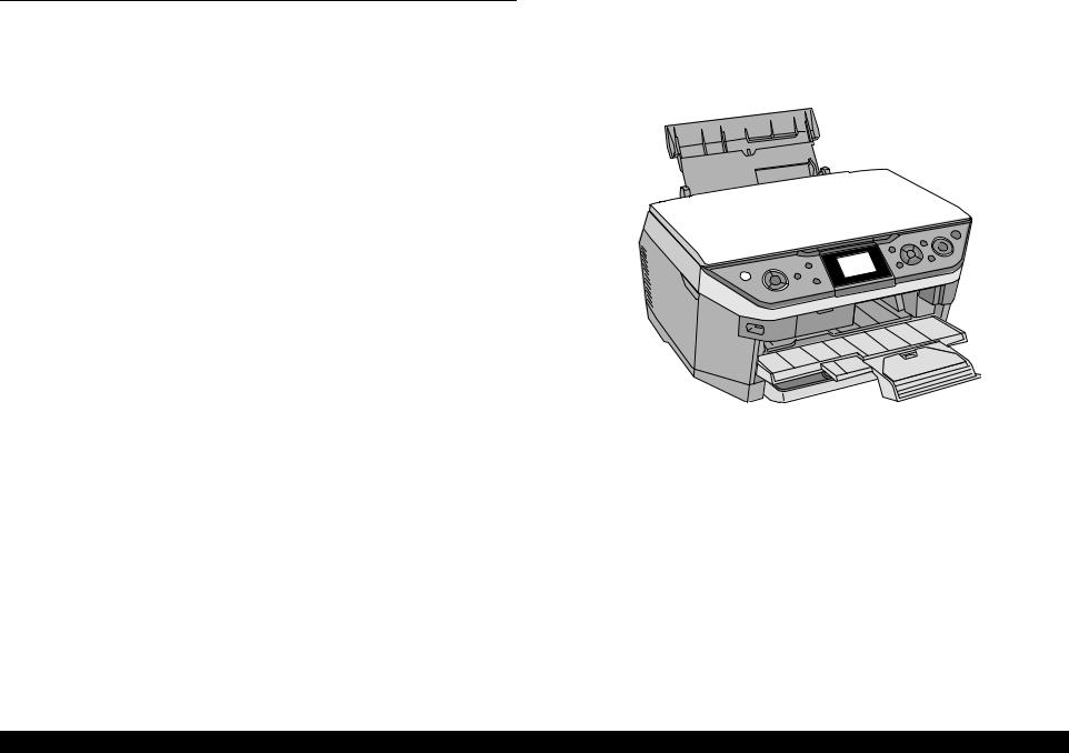
Dimensions
Dimensions:446 mm (W) x 432 mm (D) x 237 mm (H)
(with the ASF and stacker closed. Excludes the duplex unit)
Weight: 12.0 kg
(Excludes ink cartridges, CDR tray, duplex unit and power cable)
Figure 1-1. External View
PRODUCT DESCRIPTION |
Features |
10 |
EPSON Stylus Photo RX680/RX685/RX690 |
Revision A |
1.2 |
Printing Specifications |
|||
1.2.1 |
Basic Specifications |
|||
|
|
Table 1-1. Printer Specifications |
||
|
|
|
|
|
|
Item |
|
Specifications |
|
|
|
|||
Print method |
On-demand ink jet |
|||
|
|
|
|
|
|
|
Black: |
90 nozzles x 1 |
|
Nozzle configuration |
Color: |
90 nozzles x 5 |
||
|
|
|
(Cyan, Magenta, Yellow, Light Cyan, Light Magenta) |
|
|
|
|||
Print direction |
Bi-directional minimum distance printing (logic seeking) |
|||
|
|
|
||
|
|
Horizontal x Vertical (dpi) |
||
Print resolution |
• 360 x 180 |
• 720 x 540 |
||
• 360 x 360 |
• 720 x 720 |
|||
|
|
|||
|
|
• 720 x 360 |
• SMGA 5760 x 1440 (1440 x 1440) |
|
|
|
|
||
|
|
• ESC/P Raster command |
||
Control code |
• ESC/P-R (RGB) command |
|||
|
|
• EPSON Remote command |
||
|
|
|
||
|
|
Character code: Alphanumeric with expanded graphics (PC437) |
||
Internal font |
|
ASCII, 20H to 7FH only |
||
Font: |
EPSON original font |
|||
|
|
|||
|
|
|
Alphanumeric font: Courier |
|
|
|
|
||
Input buffer size |
64 Kbytes |
|
||
|
|
|
||
Paper feed method |
Friction feed |
|
||
|
|
|
||
Paper path |
• Top feed, front out (front paper cassette) |
|||
• Front feed, front out (rear ASF) |
||||
|
|
|||
|
|
|||
Paper feed rates |
T.B.D. mm/sec (at 25.4 mm feed) |
|||
|
|
|||
PF interval |
Programmable in 0.01764 mm (1/1440 inch) steps |
|||
|
|
|
|
|
1.2.2 Ink Cartridge
The product numbers of the Epson ink cartridges for this printer are shown below.
Table 1-2. Product No. of Ink Cartridges
Color |
EAI |
Euro |
Asia, CISMEA |
|
Black |
T0771 (S) |
T0801 |
T0811 (S) |
|
T0781 (SS) |
T0821 (SS) |
|||
|
|
|||
|
|
|
|
|
Cyan |
T0772 (S) |
T0802 |
T0812 (S) |
|
T0782 (SS) |
T0822 (SS) |
|||
|
|
|||
|
|
|
|
|
Magenta |
T0773 (S) |
T0803 |
T0813 (S) |
|
T0783 (SS) |
T0823 (SS) |
|||
|
|
|||
|
|
|
|
|
Yellow |
T0774 (S) |
T0804 |
T0814 (S) |
|
T0784 (SS) |
T0824 (SS) |
|||
|
|
|||
|
|
|
|
|
Light Cyan |
T0775 (S) |
T0805 |
T0815 (S) |
|
T0785 (SS) |
T0825 (SS) |
|||
|
|
|||
|
|
|
|
|
Light Magenta |
T0776 (S) |
T0806 |
T0816 (S) |
|
T0786 (SS) |
T0826 (SS) |
|||
|
|
|||
|
|
|
|
Shelf life
Two years from production date (if unopened), six months after opening package.
Storage Temperature
Table 1-3. Storage Temperature
Situation |
Storage Temperature |
Limit |
|
When stored in individual boxes |
-20 oC to 40 oC |
|
|
(-4oF to 104oF) |
1 month max. at 40 oC |
||
|
|||
When installed in main unit |
-20 oC to 40 oC |
(104oF) |
|
(-4oF to 104oF) |
|
||
|
|
Dimension
12.7 mm (W) x 68 mm (D) x 47 mm (H)
CAUTION Do not use expired ink cartridges.
The ink in the ink cartridge freezes at -16 °C (3.2 oF). It takes
about three hours under 25 °C (77oF) until the ink thaws and becomes usable.
PRODUCT DESCRIPTION |
Printing Specifications |
11 |
EPSON Stylus Photo RX680/RX685/RX690 |
Revision A |
1.2.3 Print Mode
Table 1-4. Print Mode (Color/Monochrome)
Media |
Print Mode |
Resolution |
Dot Size |
Bi-d |
Micro |
Border |
|
(H x V) dpi |
(cps*1) |
Weave |
-less |
||||
• Plain paper |
Draft 1 |
360x180 |
Eco |
ON |
OFF |
NA |
|
• Premium Bright |
(Fast economy) |
(450cps) |
|||||
|
|
|
|
||||
White Paper (EAI) |
Draft 2 |
360x180 |
Eco |
ON |
OFF |
NA |
|
• Bright White Inkjet |
|||||||
(Economy) |
(450cps) |
||||||
|
|
|
|
||||
Paper (others) |
|
|
|
|
|
|
|
Normal |
360x360 |
MC2-1 |
ON |
OFF |
NA |
||
|
|||||||
|
(360cps) |
||||||
|
|
|
|
|
|
||
|
Photo Fine |
720x720 |
MC1-1 |
ON |
ON |
NA |
|
|
(240cps) |
||||||
|
|
|
|
|
|
||
|
|
|
|
|
|
|
|
• Ultra Premium |
Photo*2 |
720x720 |
MC1-2 |
ON |
ON |
OK |
|
Glossy Photo Paper |
(1.0 pass) |
(240cps) |
|||||
(EAI) |
|
|
|
|
|
|
|
Photo*2 |
720x720 |
MC2-2 |
ON |
ON |
OK |
||
• Ultra Glossy Photo |
|||||||
(2.0 pass) |
(280cps) |
||||||
Paper (others) |
|
|
|
|
|||
Super Photo |
1440x1440 |
MC1-5 |
ON |
ON |
OK |
||
|
|||||||
|
(200cps) |
||||||
|
|
|
|
|
|
||
|
|
|
|
|
|
|
|
• Photo Paper Glossy |
|
|
MC1-1 |
|
|
OK |
|
(EAI) |
Fine |
720x360 |
ON |
ON |
|||
(240cps) |
|||||||
• Glossy Photo Paper |
|
|
|
|
|
||
|
|
|
|
|
|
||
(others) |
Photo*2 |
720x720 |
MC1-2 |
ON |
ON |
OK |
|
• Premium Photo Paper |
|||||||
(1.0 pass) |
(240cps) |
||||||
Glossy (EAI) |
|
|
|
|
|||
|
|
|
|
|
|
||
• Premium Glossy |
Photo*2 |
720x720 |
MC2-2 |
|
|
OK |
|
Photo Paper (others) |
ON |
ON |
|||||
(2.0 pass) |
(280cps) |
||||||
• Premium Photo Paper |
|
|
|
|
|||
|
|
|
|
|
|
||
Semi-Gloss (EAI) |
|
|
MC1-5 |
|
|
OK |
|
• Premium Semigloss |
Super Photo |
1440x1440 |
ON |
ON |
|||
(200cps) |
|||||||
Photo Paper (other) |
|
|
|
|
|
||
|
|
|
|
|
|
||
|
|
|
|
|
|
|
|
• Premium |
Photo |
720x720 |
MC2-2 |
ON |
ON |
OK |
|
Presentation Paper |
(2.0 pass) |
(280cps) |
|||||
|
|
|
|
||||
Matte (EAI) |
|
|
|
|
|
|
|
|
|
MC1-5 |
|
|
|
||
• Matte Paper Heavy- |
Super Photo |
1440x1440 |
ON |
ON |
OK |
||
(200cps) |
|||||||
weight (others) |
|
|
|
|
|
||
|
|
|
|
|
|
||
|
|
|
|
|
|
|
Table 1-4. Print Mode (Color/Monochrome)
Media |
Print Mode |
Resolution |
Dot Size |
Bi-d |
Micro |
Border |
|
(H x V) dpi |
(cps*1) |
Weave |
-less |
||||
• Presentation Paper |
|
|
|
|
|
|
|
Matte (EAI) |
Photo |
720x720 |
MC2-2 |
ON |
ON |
NA |
|
• Photo Quality Inkjet |
(2.0 pass) |
(280cps) |
|||||
|
|
|
|
||||
Paper (others) |
|
|
|
|
|
|
|
|
|
|
|
|
|
|
|
|
Normal |
360x360 |
MC2-1 |
OFF |
OFF |
NA |
|
|
(360cps) |
||||||
Envelope |
|
|
|
|
|
||
Photo Fine |
720x720 |
MC1-1 |
OFF |
ON |
NA |
||
|
|||||||
|
(240cps) |
||||||
|
|
|
|
|
|
||
|
|
|
|
|
|
|
|
Photo stickers |
Photo |
720x720 |
MC2-2 |
ON |
ON |
NA |
|
(2.0 pass) |
(280cps) |
||||||
|
|
|
|
|
|||
|
|
|
|
|
|
|
|
• Iron-On Transfer |
|
|
|
|
|
|
|
Paper (EAI) |
|
|
MC1-1 |
|
|
|
|
• Iron-On Cool Peal |
Photo Fine |
720x720 |
OFF |
ON |
NA |
||
(240cps) |
|||||||
Transfer Paper |
|
|
|
|
|
||
|
|
|
|
|
|
||
(others) |
|
|
|
|
|
|
|
|
|
|
|
|
|
|
|
CD/DVD label |
Super Photo |
1440x1440 |
MC1-5 |
ON |
ON |
NA |
|
(200cps) |
|||||||
|
|
|
|
|
|
||
|
|
|
|
|
|
|
|
High-quality CD/DVD |
Super Photo |
1440x1440 |
MC1-5 |
ON |
ON |
NA |
|
label |
(200cps) |
||||||
|
|
|
|
|
|||
|
|
|
|
|
|
|
Note *1: cps = character per second
*2: Photo mode uses 1.0 pass or 2.0 pass depending on the paper size. 1.0 pass supported size: 4”x6”
2.0 pass supported size: 5”x7”, 8”x10”, Letter, A4
PRODUCT DESCRIPTION |
Printing Specifications |
12 |

EPSON Stylus Photo RX680/RX685/RX690 |
Revision A |
1.2.4 Supported Paper
The table below lists the paper type and sizes supported by the printer. The Supported paper type and sizes vary depending on destinations (between EAI, EUR, and Asia).
Table 1-5. Supported Paper
|
|
|
Thickne |
Weight |
|
EAI |
|
|
EUR |
|
|
Asia |
|
Paper Path |
|||
Paper Name |
|
Paper Size |
ss |
|
|
|
|
|
|
||||||||
|
|
|
|
|
|
|
|
|
|
|
|
|
|
||||
|
|
|
|
|
|
|
|
|
|
|
|
|
|
|
|||
|
|
|
mm |
g/m2 |
lb. |
P*1 |
B*2 |
D*3 |
P*1 |
B*2 |
D*3 |
P*1 |
B*2 |
D*3 |
F*4 |
R*5 |
|
|
Legal |
215.9 x 355.6 mm (8.5”x14”) |
|
|
|
Y |
- |
- |
Y |
- |
- |
Y |
- |
- |
- |
Y |
|
|
|
|
|
|
|
|
|
|
|
|
|
|
|
|
|
|
|
|
Letter |
215.9 x 279.4 mm (8.5”x11”) |
|
|
|
Y |
- |
Y |
Y |
- |
Y |
Y |
- |
Y |
Y |
Y |
|
|
|
|
|
|
|
|
|
|
|
|
|
|
|
|
|
|
|
|
A4 |
210 x 297 mm (8.3”x11.7”) |
|
|
|
Y |
- |
Y |
Y |
- |
Y |
Y |
- |
Y |
Y |
Y |
|
|
|
|
|
|
|
|
|
|
|
|
|
|
|
|
|
|
|
|
B5 |
182 x 257 mm (7.2”x10.1”) |
0.08- |
|
|
- |
- |
Y |
Y |
- |
Y |
Y |
- |
Y |
Y |
Y |
|
Plain paper |
|
|
64-90 |
17-24 |
|
|
|
|
|
|
|
|
|
|
|
||
A5 |
148 x 210 mm (5.8”x8.3”) |
- |
- |
- |
Y |
- |
- |
Y |
- |
- |
Y |
Y |
|||||
0.11 |
|||||||||||||||||
|
|
|
|||||||||||||||
|
Half Letter |
139.7 x 215.9 mm (5.5"x8.5”) |
|
|
|
Y |
- |
- |
- |
- |
- |
- |
- |
- |
- |
- |
|
|
|
|
|
|
|
|
|
|
|
|
|
|
|
|
|
|
|
|
A6 |
105 x 148 mm (4.1”x5.8”) |
|
|
|
Y |
- |
- |
Y |
- |
- |
Y |
- |
- |
Y |
Y |
|
|
|
|
|
|
|
|
|
|
|
|
|
|
|
|
|
|
|
|
User |
89 x 127216 x 297 mm*6 |
|
|
|
Y |
- |
- |
Y |
- |
- |
Y |
- |
- |
Y*6 |
Y*7 |
|
|
Defined |
50.8x127 - 216x1117.9 mm*7 |
|
|
|
||||||||||||
|
|
|
|
|
|
|
|
|
|
|
|
|
|
|
|||
Premium Inkjet Plain Paper |
A4 |
210 x 297 mm (8.3”x11.7”) |
0.11 |
80 |
21 |
- |
- |
- |
Y |
- |
Y |
Y |
- |
Y |
Y |
Y |
|
|
|
|
|
|
|
|
|
|
|
|
|
|
|
|
|
|
|
Premium Bright White Paper (EAI) |
Letter |
215.9 x 279.4 mm (8.5”x11”) |
0.11 |
90 |
24 |
Y |
- |
Y |
- |
- |
- |
- |
- |
- |
Y |
Y |
|
|
|
|
|
|
|
|
|
|
|
|
|
|
|
|
|
|
|
Bright White Inkjet Paper (others) |
A4 |
210 x 297 mm (8.3”x11.7”) |
0.13 |
92.5 |
25 |
- |
- |
- |
Y |
- |
Y |
Y |
- |
Y |
Y |
Y |
|
|
|
|
|
|
|
|
|
|
|
|
|
|
|
|
|
|
|
|
Letter |
215.9 x 279.4 mm (8.5”x11”) |
|
|
|
Y |
Y |
- |
- |
- |
- |
- |
- |
- |
Y |
Y |
|
|
|
|
|
|
|
|
|
|
|
|
|
|
|
|
|
|
|
|
A4 |
210 x 297 mm (8.3”x11.7”) |
|
|
|
- |
- |
- |
Y |
Y |
- |
Y |
Y |
- |
Y |
Y |
|
Ultra Premium Photo Paper Glossy (EAI) |
|
|
|
|
|
|
|
|
|
|
|
|
|
|
|
|
|
8” x 10” |
203.2 x 254 mm |
0.30 |
290 |
77 |
Y |
Y |
- |
- |
- |
- |
- |
- |
- |
Y |
Y |
||
Ultra Glossy Photo Paper (others) |
|||||||||||||||||
|
|
|
|
|
|
|
|
|
|
|
|
|
|
|
|
||
|
5” x 7” |
127 x 178 mm |
|
|
|
Y |
Y |
- |
Y |
Y |
- |
- |
- |
- |
Y |
Y |
|
|
|
|
|
|
|
|
|
|
|
|
|
|
|
|
|
|
|
|
4” x 6” |
101.6 x 152.4 mm |
|
|
|
Y |
Y |
- |
Y |
Y |
- |
Y |
Y |
- |
Y |
Y |
|
|
|
|
|
|
|
|
|
|
|
|
|
|
|
|
|
|
|
Note *:*1: indicates whether the paper type/size is supported or not. *2: indicates whether Borderless printing is available or not. *3: indicates whether duplex printing is available or not. *4: indicates whether the paper type/size is supported for front feeding (front cassette). *5: indicates whether the paper type/size is supported for rear feeding (rear ASF).
The underlined “Y” indicates the default feeder. *6,*7: the available user defined size differs between the front and the rear feeders. *6 indicates the value for the front feeder, and *7 indicates that for the rear.
PRODUCT DESCRIPTION |
Printing Specifications |
13 |

EPSON Stylus Photo RX680/RX685/RX690 |
|
|
|
|
|
|
|
|
|
|
|
|
Revision A |
||||
|
|
Table 1-5. Supported Paper |
|
|
|
|
|
|
|
|
|
|
|
||||
|
|
|
|
|
|
|
|
|
|
|
|
|
|
|
|
|
|
|
|
|
Thickne |
Weight |
|
EAI |
|
|
EUR |
|
|
Asia |
|
Paper Path |
|||
Paper Name |
|
Paper Size |
ss |
|
|
|
|
|
|
||||||||
|
|
|
|
|
|
|
|
|
|
|
|
|
|
||||
|
|
|
|
|
|
|
|
|
|
|
|
|
|
|
|||
|
|
|
|
|
|
|
|
|
|
|
|
|
|
|
|
|
|
|
|
|
mm |
g/m2 |
lb. |
P*1 |
B*2 |
D*3 |
P*1 |
B*2 |
D*3 |
P*1 |
B*2 |
D*3 |
F*4 |
R*5 |
|
|
Letter |
215.9 x 279.4 mm (8.5”x11”) |
|
|
|
Y |
Y |
- |
- |
- |
- |
- |
- |
- |
Y |
Y |
|
|
|
|
|
|
|
|
|
|
|
|
|
|
|
|
|
|
|
|
A4 |
210 x 297 mm (8.3”x11.7”) |
|
|
|
Y |
Y |
- |
Y |
Y |
- |
Y |
Y |
- |
Y |
Y |
|
|
|
|
|
|
|
|
|
|
|
|
|
|
|
|
|
|
|
Premium Photo Paper Glossy (EAI) |
8” x 10” |
203.2 x 254 mm |
0.27 |
255 |
68 |
Y |
Y |
- |
- |
- |
- |
- |
- |
- |
Y |
Y |
|
|
|
|
|
|
|
|
|
|
|
|
|
|
|||||
Premium Glossy Photo Paper (others) |
5” x 7” |
127 x 178 mm |
Y |
Y |
- |
Y |
Y |
- |
Y |
Y |
- |
Y |
Y |
||||
|
|
|
|||||||||||||||
|
|
|
|
||||||||||||||
|
|
|
|
|
|
|
|
|
|
|
|
|
|
|
|
|
|
|
4" x 6" |
101.6 x 152.4 mm |
|
|
|
Y |
Y |
- |
Y |
Y |
- |
Y |
Y |
- |
Y |
Y |
|
|
|
|
|
|
|
|
|
|
|
|
|
|
|
|
|
|
|
|
16:9 wide |
102 x 181 mm (4”x7.11”) |
|
|
|
- |
- |
- |
Y |
- |
- |
- |
- |
- |
Y |
Y |
|
|
|
|
|
|
|
|
|
|
|
|
|
|
|
|
|
|
|
|
Letter |
215.9 x 279.4 mm (8.5”x11”) |
|
|
|
Y |
Y |
- |
- |
- |
- |
- |
- |
- |
Y |
Y |
|
|
|
|
|
|
|
|
|
|
|
|
|
|
|
|
|
|
|
Photo Paper Glossy (EAI) |
A4 |
210 x 297 mm (8.3”x11.7”) |
0.25 |
258 |
68 |
Y |
Y |
- |
Y |
Y |
- |
Y |
Y |
- |
Y |
Y |
|
|
|
|
|
|
|
|
|
|
|
|
|
|
|||||
Glossy Photo Paper (others) |
5” x 7” |
127 x 178 mm |
- |
- |
- |
Y |
Y |
- |
- |
- |
- |
Y |
Y |
||||
|
|
|
|||||||||||||||
|
|
|
|
||||||||||||||
|
|
|
|
|
|
|
|
|
|
|
|
|
|
|
|
|
|
|
4” x 6” |
101.6 x 152.4 mm |
|
|
|
Y |
Y |
- |
Y |
Y |
- |
Y |
Y |
- |
Y |
Y |
|
|
|
|
|
|
|
|
|
|
|
|
|
|
|
|
|
|
|
|
Letter |
215.9 x 279.4 mm (8.5”x11”) |
|
|
|
Y |
Y |
- |
- |
- |
- |
- |
- |
- |
- |
- |
|
Premium Photo Paper Semi-gloss (EAI) |
|
|
|
|
|
|
|
|
|
|
|
|
|
|
|
|
|
A4 |
210 x 297 mm (8.3”x11.7”) |
0.27 |
250 |
66 |
- |
- |
- |
Y |
Y |
- |
Y |
Y |
- |
Y |
Y |
||
Premium Semigloss Photo Paper (others) |
|||||||||||||||||
|
|
|
|
|
|
|
|
|
|
|
|
|
|
|
|
||
|
4” x 6” |
101.6 x 152.4 mm |
|
|
|
Y |
Y |
- |
Y |
Y |
- |
Y |
Y |
- |
Y |
Y |
|
|
|
|
|
|
|
|
|
|
|
|
|
|
|
|
|
|
|
Ultra Premium Photo Paper Luster |
Letter |
215.9 x 279.4 mm (8.5”x11”) |
0.27 |
250 |
66 |
Y |
Y |
- |
- |
- |
- |
- |
- |
- |
Y |
Y |
|
|
|
|
|
|
|
|
|
|
|
|
|
|
|
|
|
|
|
Premium Presentation Paper Matte (EAI) |
Letter |
215.9 x 279.4 mm (8.5”x11”) |
|
|
|
Y |
Y |
- |
- |
- |
- |
- |
- |
- |
Y |
Y |
|
|
|
|
|
|
|
|
|
|
|
|
|
|
|
|
|
||
A4 |
210 x 297 mm (8.3”x11.7”) |
0.23 |
167 |
44 |
- |
- |
- |
Y |
Y |
- |
Y |
Y |
- |
Y |
Y |
||
Matte Paper Heavy-weight (others) |
|||||||||||||||||
|
|
|
|
|
|
|
|
|
|
|
|
|
|
|
|||
|
8” x 10” |
203.2 x 254 mm |
|
|
|
Y |
Y |
- |
- |
- |
- |
- |
- |
- |
Y |
Y |
|
|
|
|
|
|
|
|
|
|
|
|
|
|
|
|
|
|
|
Double-sided Matte Paper |
Letter |
215.9 x 279.4 mm (8.5”x11”) |
0.22 |
185 |
49 |
Y |
- |
- |
- |
- |
- |
- |
- |
- |
Y |
Y |
|
|
|
|
|
|
|
|
|
|
|
|
|
|
|||||
A4 |
210 x 297 mm (8.3”x11.7”) |
- |
- |
- |
Y |
- |
- |
Y |
- |
- |
Y |
Y |
|||||
|
|
|
|
||||||||||||||
|
|
|
|
|
|
|
|
|
|
|
|
|
|
|
|
|
|
Presentation Paper Matte (EAI) |
Letter |
215.9 x 279.4 mm (8.5”x11”) |
0.12 |
102 |
27 |
Y |
- |
- |
- |
- |
- |
- |
- |
- |
Y |
Y |
|
|
|
|
|
|
|
|
|
|
|
|
|
|
|||||
Photo Quality Inkjet Paper (others) |
A4 |
210 x 297 mm (8.3”x11.7”) |
Y |
- |
- |
Y |
- |
- |
Y |
- |
- |
Y |
Y |
||||
|
|
|
|||||||||||||||
|
|
|
|
||||||||||||||
|
|
|
|
|
|
|
|
|
|
|
|
|
|
|
|
|
|
Note *:*1: indicates whether the paper type/size is supported or not. *2: indicates whether Borderless printing is available or not. *3: indicates whether duplex printing is available or not. *4: indicates whether the paper type/size is supported for front feeding (front cassette). *5: indicates whether the paper type/size is supported for rear feeding (rear ASF).
The underlined “Y” indicates the default feeder.
PRODUCT DESCRIPTION |
Printing Specifications |
14 |

EPSON Stylus Photo RX680/RX685/RX690 |
|
|
|
|
|
|
|
|
|
|
|
|
Revision A |
||||
|
|
Table 1-5. Supported Paper |
|
|
|
|
|
|
|
|
|
|
|
||||
|
|
|
|
|
|
|
|
|
|
|
|
|
|
|
|
|
|
|
|
|
Thickne |
Weight |
|
EAI |
|
|
EUR |
|
|
Asia |
|
Paper Path |
|||
Paper Name |
|
Paper Size |
ss |
|
|
|
|
|
|
||||||||
|
|
|
|
|
|
|
|
|
|
|
|
|
|
||||
|
|
|
|
|
|
|
|
|
|
|
|
|
|
|
|||
|
|
|
|
|
|
|
|
|
|
|
|
|
|
|
|
|
|
|
|
|
mm |
g/m2 |
lb. |
P*1 |
B*2 |
D*3 |
P*1 |
B*2 |
D*3 |
P*1 |
B*2 |
D*3 |
F*4 |
R*5 |
|
|
#10 |
104.8 x 241.3 mm |
|
|
|
Y |
- |
- |
Y |
- |
- |
Y |
- |
- |
- |
- |
|
|
(4.125”x9.5”) |
|
|
|
|||||||||||||
|
|
|
|
|
|
|
|
|
|
|
|
|
|
|
|
||
Envelopes |
|
|
- |
75-90 |
20-24 |
|
|
|
|
|
|
|
|
|
|
|
|
#DL |
110 x 220 mm |
- |
- |
- |
Y |
- |
- |
Y |
- |
- |
- |
- |
|||||
|
|
|
|
||||||||||||||
|
|
|
|
|
|
|
|
|
|
|
|
|
|
|
|
|
|
|
#C6 |
114 x 162 mm |
|
|
|
- |
- |
- |
Y |
- |
- |
Y |
- |
- |
- |
- |
|
|
|
|
|
|
|
|
|
|
|
|
|
|
|
|
|
|
|
Iron-On Transfer Paper (EAI) |
Letter |
215.9 x 279.4 mm (8.5”x11”) |
0.14 |
130 |
35 |
Y |
- |
- |
- |
- |
- |
- |
- |
- |
- |
Y |
|
Iron-On Cool Peal Transfer Paper (others) |
A4 |
210 x 297 mm (8.3”x11.7”) |
- |
- |
- |
Y |
- |
- |
Y |
- |
- |
- |
Y |
||||
|
|
|
|||||||||||||||
|
|
|
|
|
|
|
|
|
|
|
|
|
|
|
|
|
|
Photo Stickers 16 |
A6 |
105 x 148 mm (4.1”x5.8”) |
0.19 |
|
- |
- |
- |
- |
- |
- |
- |
Y |
- |
- |
- |
Y |
|
|
|
|
|
|
|
|
|
|
|
|
|
|
|
|
|
|
|
Photo Stickers 4 |
A6 |
105 x 148 mm (4.1”x5.8”) |
0.19 |
|
- |
- |
- |
- |
- |
- |
- |
Y |
- |
- |
- |
Y |
|
|
|
|
|
|
|
|
|
|
|
|
|
|
|
|
|
|
|
CD/DVD |
ø12cm |
ø12cm |
- |
|
- |
Y |
- |
- |
Y |
- |
- |
Y |
- |
- |
Y*8 |
- |
|
|
|
|
|
|
|
|
|
|
|
|
|
|
|
|
|
||
CD/DVD Premium Surface |
ø8cm |
ø8cm |
- |
|
- |
Y |
- |
- |
Y |
- |
- |
Y |
- |
- |
Y*8 |
- |
|
Note *:*1: indicates whether the paper type/size is supported or not. *2: indicates whether Borderless printing is available or not. *3: indicates whether duplex printing is available or not. *4: indicates whether the paper type/size is supported for front feeding (front cassette). *5: indicates whether the paper type/size is supported for rear feeding (rear ASF).
The underlined “Y” indicates the default feeder. *8: using the CD/DVD tray.
CAUTION Make sure the paper is not wrinkled, fluffed, torn, or folded.
The curve of paper must be 5 mm or below.
When printing on an envelope, be sure the flap is folded neatly.
Do not use the adhesive envelopes.
Do not use double envelopes and cellophane window envelopes.
PRODUCT DESCRIPTION |
Printing Specifications |
15 |
EPSON Stylus Photo RX680/RX685/RX690 |
Revision A |
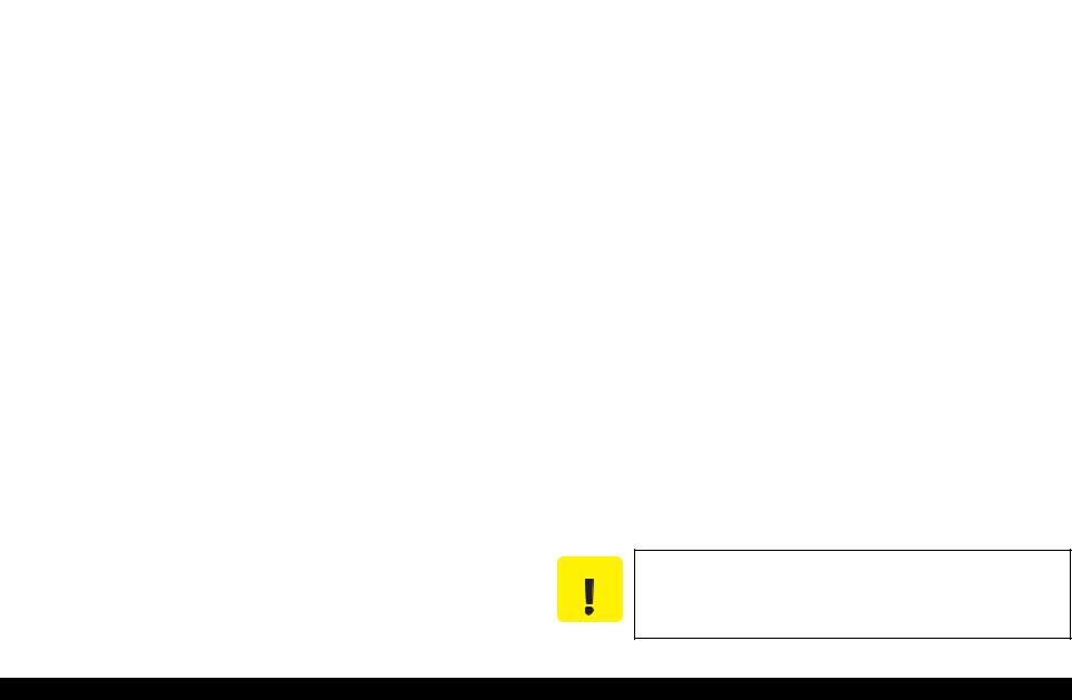
1.2.5 Printing Area
The printing area for this printer is shown below.
Table 1-6. Printing Area (Margins)
Print Mode |
Paper Size |
|
Margin |
|
||
Left |
Right |
Top |
Bottom |
|||
|
|
|||||
|
|
|
|
|
|
|
Standard print |
Any size |
3 mm |
3 mm |
3 mm |
3 mm |
|
|
|
|
|
|
||
Envelope |
5 mm |
5 mm |
3 mm |
20 mm |
||
|
||||||
|
|
|
|
|
|
|
Borderless |
A4/Letter to 5” x 7” |
2.54 mm* |
2.54 mm* |
2.96 mm* |
4.02 mm* |
|
4” x 6” |
1.34 mm* |
2.54 mm* |
||||
|
|
|||||
|
|
|
|
|
|
|
Note* : The margins for Borderless print are margins that bleed off the edges of paper.
Cut Sheet (Standard) |
Cut Sheet (Borderless) |
|
Envelope |
||
LM |
RM |
LM |
RM |
LM |
RM |
|
TM |
|
TM |
|
TM |
|
|
|
|
|
Print Area |
|
Print Area |
|
Print Area |
|
|
|
BM |
|
|
|
BM |
|
|
|
|
|
|
|
|
|
|
|
|
|
|
|
|
|
|
|
|
|
|
|
|
Paper |
|
SIze |
|
|
|
|
|
|
|
|
|
|
|
|
|
|
|
|
|
|
|
||
Paper Size |
|
|
|
|
|
|
|
BM |
|
|||||||||||
|
|
|
|
|||||||||||||||||
|
|
|
|
|
|
|
|
|
|
|
|
|
|
|
|
|
|
|
|
|
Paper Feed Direction
Figure 1-2. Printing Area
1.3 Scanner Specifications
|
Table 1-7. Scanner Specifications |
|
|
|
|
Item |
|
Specification |
|
|
|
Scanner type |
|
Flatbed, color |
|
|
|
Scanning method |
|
Moving carriage, stationary document |
|
|
|
Home position |
|
Far left corner |
|
|
|
Photoelectric device |
|
CIS |
|
|
|
Light source |
|
LED |
|
|
|
Maximum document size |
|
US letter, or A4 size |
|
|
|
Scanning range |
|
8.5 x 11.7 inches (216 x 297 mm) |
|
|
|
Maximum resolution |
|
Main scan: 1200 dpi / Sub scan: 2400 dpi |
|
|
|
Maximum effective pixels |
|
10,200 x 14,040 pixels (1200dpi) |
|
|
|
Pixel depth |
|
16 bit per pixel (input), 1 or 8 bit per pixel (output) |
|
|
|
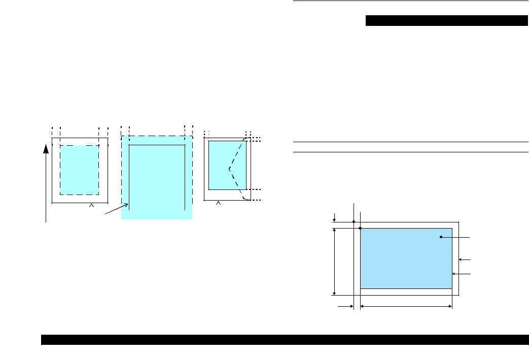
SCANNING RANGE
Table 1-8. Scanning Range
RW (read width) |
OLM (left margin) |
RL (read length) |
OTM (top margin) |
|
|
|
|
|
|
216 mm (8.5”) |
1.5 mm +/- 1 mm |
297 mm (11.7”) |
1.5 mm +/- 1 mm |
|
|
|
|
|
Home position
Scanning start position
 Scanning direction
OLM |
|
|
|
|
a |
Original |
|
|
(face down) |
||
RW |
Scan bed |
||
|
Scanning range |
||
|
|
|
|
|
OTM |
RL |
|
|
|
|
|
Figure 1-3. Scanning Range
PRODUCT DESCRIPTION |
Scanner Specifications |
16 |

EPSON Stylus Photo RX680/RX685/RX690 |
Revision A |
1.4 |
General Specifications |
|
|||
1.4.1 |
Electrical Specifications |
|
|||
|
|
Table 1-9. Primary Power Specifications |
|
||
|
|
|
|
|
|
Item |
|
100-120 V model |
220-240 V model |
||
|
|
|
|
|
|
Rated power supply voltage |
100 to 120 VAC |
|
220 to 240 VAC |
||
|
|
|
|
||
Input voltage range |
90 to 132 VAC |
|
198 to 264 VAC |
||
|
|
|
|
||
Rated current |
0.6 A (Max 1.2 A) |
|
0.3 A (Max 0.6 A) |
||
|
|
|
|||
Rated frequency |
50 to 60 Hz |
||||
|
|
||||
Input frequency range |
49.5 to 60.5 Hz |
||||
|
|
||||
Insulation resistance |
3000 V (for one minute) |
||||
|
|
|
|
|
|
|
|
Standalone copying |
20 W |
|
20 W |
|
|
|
|
|
|
Power |
|
Low Power Mode |
7.5 W |
|
8 W |
consumption |
Sleep Mode |
4 W |
|
4.5 W |
|
|
|
|
|
|
|
|
|
Powered off Mode |
0.3 W |
|
0.6 W |
|
|
|
|
|
|
Note : If the printer is not operated for more than three minutes, the printer shifts into the standby mode and reduces the current to the motor to conserve power.
1.4.2 Safety Approvals (Safety standards/EMI)
USA |
UL60950-1 |
|
FCC Part15 Subpart B Class B |
Canada |
CAN/CSA-CEI/IEC CISPR 22 Class B |
|
CAN/CSA-C22.2 No.60950-1 |
Taiwan |
CNS13438 Class B |
|
CNS14336 |
EU |
EN60950-1 |
|
EN55022 Class B |
|
EN61000-3-2, EN61000-3-3 |
|
EN55024 |
Germany |
EN60950-1 |
Russia |
GOST-R (IEC60950-1, CISPR 22) |
Singapore/Hong Kong |
IEC60950-1 |
Korea |
K60950-1 |
|
KN22 Class B |
|
K61000-4-2/-3/-4/-5/-6/-11 |
China |
GB4943 |
|
GB9254 Class B, GB17625.1 |
Australia |
AS/NZS CISPR22 Class B |
1.4.3 Acoustic Noise
36 dB (when printing from PC, on Premium Glossy Photo Paper, in the highest quality) 45 db (when copying on plain paper in the default mode)
1.4.4 Durability
Total print life
Black 16,000 pages (A4, 3.5% duty), Color 10,000 pages (A4, 5.0% duty), or five years which ever comes first
Printhead
Six billions shots (per nozzle) or five years which ever comes first
Scanner carriage
36,000 cycles of carriage movement
PRODUCT DESCRIPTION |
General Specifications |
17 |
EPSON Stylus Photo RX680/RX685/RX690 |
Revision A |
1.4.5 Environmental Conditions
Table 1-10. Environmental Conditions
Condition |
Temperature*1 |
Humidity*1,2 |
Shock |
Vibration |
|
Operating |
10 to 35°C |
20 to 80% |
1G |
0.15G, |
|
(50 to 95°F) |
(1 msec or less) |
10 to 55Hz |
|||
|
|
||||
|
|
|
|
|
|
Storage |
-20 to 40°C*3 |
5 to 85% |
2G |
0.50G, |
|
(unpacked) |
(-4°F to 104°F) |
(2 msec or less) |
10 to 55Hz |
||
|
|||||
|
|
|
|
|
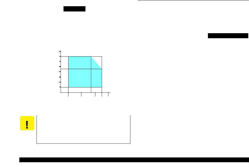
Note *1: The combined Temperature and Humidity conditions must be within the blue-shaded range shown in Figure 1-4.
*2: No condensation
*3: Must be less than 1 month under 40°C.
|
90 |
|
|
|
|
|
80 |
|
|
|
|
|
70 |
|
|
|
|
|
60 |
|
|
|
|
Humidity (%) |
50 |
|
|
|
|
|
|
|
|
|
|
|
40 |
|
|
|
|
|
30 |
|
|
|
|
|
20 |
|
|
|
|
|
|
|
27/80 |
|
|
|
10/50 |
20/68 |
30/86 |
35/95 |
40/104 |
Temperature (°C/°F)
Figure 1-4. Temperature/Humidity Range
CAUTION |
When returning the repaired printer to the customer, make sure |
|
the Printhead is covered with the cap and the ink cartridge is |
|
installed. |
If the Printhead is not covered with the cap when the printer is off, turn on the printer with the ink cartridge installed, make sure the Printhead is covered with the cap, and then turn the printer off.
1.5 Interface
The printer has USB interfaces and memory card slots of the following specifications.
1.5.1 USB Interfaces
The printer has two USB ports; USB Device port for connecting with a host device such as a computer, and USB Host port for connecting with an external device such as DSC (Digital Still Camera).
Table 1-11. USB Interface Specification
Item |
USB Device Port |
|
USB Host Port* |
|
|
|
|
|
|
|
• Universal Serial Bus |
|
• Universal Serial Bus |
|
|
Specifications Revision 2.0 |
|
Specifications Revision 2.0 |
|
|
• Universal Serial Bus Device |
|
• Universal Serial Bus Mass |
|
Standards |
Class Definition for Printing |
|
Storage Class Bulk-Only |
|
Devices Version 1.1 |
|
Transport Revision 1.0 |
||
|
|
|||
|
• Universal Serial Bus Mass |
|
|
|
|
Storage Class Bulk-Only |
|
|
|
|
Transport Revision 1.0 |
|
|
|
Transfer rate |
480Mbps (High Speed Device) |
|||
|
|
|
||
Data format |
|
NRZI |
||
|
|
|
|
|
Compatible |
USB Series B |
|
USB Series A |
|
connector |
|
|||
|
|
|
||
|
|
|
|
|
Maximum cable |
Less than 2 m |
|||
length |
||||
|
|
|
||
|
|
|
|
|
Note* : The following devices can be connected to the USB Host port.
•DSC compliant with USB Direct Print Protocol Specification Rev1.0.
•DSC compliant with CIPA DC-001-2003 (PictBridge) Specification.
•Devices compliant with Universal Serial Bus Mass Storage Class Bulk-Only Transport Revision 1.0, and the Subclass code is one of the followings.
0x06 (SCSI transparent command set)
0x05 (SFF-8070i command set)
0x02 (SFF-8020i command set)
PRODUCT DESCRIPTION |
Interface |
18 |

EPSON Stylus Photo RX680/RX685/RX690 |
Revision A |
1.5.2 Memory Card Slots
Table 1-12. List of Supported Memory Card
Priority |
Slot |
Compatible memory card |
Standard |
Max. |
Remarks |
|
capacity |
||||||
|
|
|
|
|
||
|
|
|
|
|
|
|
|
|
Memory Stick |
“MemoryStick Standard” Format Specification Ver.1.42-00 compatible |
128MB |
Includes versions with memory select function |
|
|
|
|
|
|
|
|
|
|
MagicGate Memory Stick |
|
128MB |
Copy protection function is not supported |
|
|
|
|
|
|
|
|
|
|
MagicGate Memory Stick Duo |
|
|
An adapter should be used |
|
|
|
|
|
|
|
|
|
Memory Stick/ |
Memory Stick PRO |
Memory Stick PRO Format Specifications-without security Ver.1.02-00 compatible |
4GB |
Copy protection function is not supported |
|
|
|
|
|
|
||
|
Memory Stick |
Memory Stick Duo |
MemoryStick Duo Format Specification Ver.1.11-00 compatible |
|
The Memory Stick Duo adapter should be |
|
|
PRO |
|
used |
|||
|
|
|
|
|||
|
|
|
|
|
|
|
|
|
Memory Stick Pro Duo |
MemoryStick PRO Duo Format Specification Ver.1.02-00 compatible |
|
The Memory Stick Duo adapter should be |
|
|
|
|
used. |
|||
|
|
|
|
|
||
|
|
|
|
|
|
|
1 |
|
Memory Stick micro |
Memory Stick Micro Format Specification Ver.1.02-00 compatible |
|
The Memory Stick adapter for standard size |
|
|
|
should be used. |
||||
|
|
|
|
|
||
|
|
|
|
|
|
|
|
|
SD (Security Digital) |
|
2GB |
|
|
|
|
|
|
|
||
|
|
miniSD/microSD |
SD Memory Card Specifications / PART1. Physical Layer Specification Ver. 2.0 |
The SD adapter should be used |
||
|
|
|
||||
|
|
|
|
|
||
|
|
SDHC |
|
Speed Class is not supported |
||
|
|
compatible |
|
|||
|
SD/MMC |
|
8GB |
|
||
|
miniSDHC/microSDHC |
|
The SD adapter should be used |
|||
|
|
|
|
Speed Class is not supported |
||
|
|
|
|
|
||
|
|
|
|
|
|
|
|
|
MultiMediaCard |
MultiMediaCard Standard Ver. 4.1 compatible |
64MB/ |
Only MultiMediaCard Plus supports 4GB |
|
|
|
MultiMediaCard Plus |
4GB |
|||
|
|
|
|
|||
|
|
|
|
|
|
|
|
xD-Picture card |
xD-Picture card |
xD-Picture Card Specification Ver.1.20 compatible |
2GB |
Type M/H supported |
|
|
|
|
|
|
|
|
2 |
CF Type II |
Compact Flash |
CF+ and CompactFlash Specification Revision 3.0 compatible |
4GB |
True-IDE compatible memory card only |
|
|
|
|
|
|||
Microdrive |
|
|
|
|||
|
|
|
|
|
||
|
|
|
|
|
|
Note: • Memory Stick/PRO, SD/MMC and xD-Picture Card shares the same slot.
•When cards are inserted in the two slots at once, the slot which will be accessed first is determined according to the priority shown in the table.
•To select a card that has been inserted in a non-active slot, first remove the card in the active slot.
•In memory card direct printing mode, the image files in the active slot are valid and have assigned frame numbers. The number of images will not change if a card is inserted in another nonselected slot.
•When the card inserted in the slot is accessed from the PC, only one drive is displayed at a time as a removable disk* and only the card that is in the active slot can be accessed via the removable disk. A card that has been inserted into a non-selected slot cannot be accessed.
(This is for Windows. For Macintosh, the card in the active slot will be mounted on the desktop.)
•Does not support 5V type of memory cards.
•When a memory card is being accessed, do not touch the memory card.
•For detailed information on the supported file system and formatting the memory card, refer to “1.7.2 Memory Card Direct Print Function (p.21)”.
PRODUCT DESCRIPTION |
Interface |
19 |

EPSON Stylus Photo RX680/RX685/RX690 |
Revision A |
1.6 Control Panel
1.6.1 Operation Buttons & LED
The following tables explain the functions of the buttons and LEDs on the control panel.
Table 1-13. Operation Buttons & LEDs
|
Button/LED |
Function |
|
|
|
|
|
|
|
Power |
Turns the power ON/OFF. |
|
|
|
|
|
|
Start |
Starts printing. |
|
|
|
|
|
|
Copy |
Goes to the stand alone copy mode. |
|
|
|
|
|
|
Memory Card |
Goes to the memory card direct print mode. |
|
|
|
|
|
|
Specialty Print |
Goes to the special mode that provides Print Photo Greeting Card, |
|
|
Reprint/Restore Photos, and Print on CD/DVD functions. |
|
|
|
|
|
|
|
|
|
|
|
|
• Stops operation and displays the menu screen. |
|
|
|
• Stops printing and ejects paper. |
|
|
Stop/Clear |
• Returns the print settings of the current mode to their default |
|
|
|
and displays the Top screen. (Returns to the previous screen |
Button |
|
|
during printing maintaining the current settings) |
|
|
Setup |
Goes to the Setup mode that provides maintenance menu (head |
|
|
cleaning, head alignment, etc.) and various option setting menu. |
|
|
|
|
|
|
|
|
|
|
|
Display/Crop |
Goes to the zoom setting screen for the selected image. |
|
|
Changes the image preview layout (1-up, 9-up, etc.) on the LCD. |
|
|
|
|
|
|
|
|
|
|
|
Menu |
Goes to the print setting menu screen. |
|
|
|
|
|
|
OK |
Accepts the changed settings. |
|
|
|
|
|
|
Back |
Cancels the previous operation. |
|
|
|
|
|
|
Cross Key |
Selects a menu item of setting value. |
|
|
(up/down/left/right) |
|
|
|
|
|
|
|
|
|
|
|
+ |
Sets the number of copies. |
|
|
|
|
|
|
- |
|
|
|
|
|
|
|
|
|
|
|
CD Print Tray |
Opens or closes the CD guide. |
|
|
|
|
LED* |
|
Power |
Indicates the power On/Off status. |
|
|
|
|
|
Mode |
Lights during the corresponding mode is selected. |
|
|
|
||
|
|
|
|
Note * : See Table 1-14 for more information on the LEDs.
Table 1-14. LED Functions
Printer Status |
Power LED |
Mode LED |
|
|
|
Power-on sequence |
Flashing |
OFF |
|
|
|
Power-off sequence |
Flashing |
The current mode LED flashes |
|
|
|
Fatal error |
Flashing |
All the mode LEDs flash |
|
|
|
Standby/The panel being operated |
ON |
The current mode LED lights* |
|
|
|
Printing/Scanning |
|
|
|
|
|
Printing from an external device (PC/camera) |
|
|
|
|
|
Running a head cleaning |
|
|
|
|
|
Running a nozzle check |
|
|
|
|
|
Printing head alignment pattern |
Flashing |
The current mode LED flashes* |
|
|
|
Canceling a print job |
|
|
|
|
|
Clipping of video |
|
|
|
|
|
Making a backup copy |
|
|
|
|
|
Performing Scan to Memory |
|
|
|
|
|
Running a slide show |
ON |
The memory card mode LED lights |
|
|
|
Displaying the screen-saver |
ON |
The memory card mode LED lights |
|
|
|
Power save mode |
ON |
The current mode LED lights* |
|
|
|
Note* : In the Setup mode, the mode LED corresponds to the previous mode lights.
Power LED |
|
|
|
|
|
|
|
|
|
OK Button and |
||||
|
|
|
|
Memory card Button |
|
|
|
Cross buttons |
||||||
|
Mode LED |
|
|
|
|
|
|
- Button |
|
|||||
|
|
|
|
|
|
|
||||||||
|
|
|
|
|
Setup Button LCD |
|
|
|
|
+ Button |
||||
|
|
|
|
|
|
|
|
|
||||||
|
|
|
|
|
|
|
|
|
||||||
|
|
|
|
|
|
|
|
|
|
|
||||
|
|
|
|
|
|
|
|
|
|
|
|
|
|
|
|
|
|
|
|
|
|
|
|
|
|
|
|
|
|
|
|
|
|
|
|
|
|
|
|
|
|
|
|
|
Power Button |
Display/Crop Button |
Menu Button |
Back Button |
|
Start Button |
||
|
Tray Button |
|
|
|
|
Stop / Clear settings Button |
|
|
Specialty Print Button |
|
|
|
|
|
|
|
Power Button |
|
|
Figure 1-5. Control Panel
PRODUCT DESCRIPTION |
Control Panel |
20 |

EPSON Stylus Photo RX680/RX685/RX690 |
Revision A |
1.7 Specifications of Each Function
1.7.1 Stand-alone Copy Function
With the press of the Copy button, the printer goes into the Copy mode and displays a menu for copying. The menu allows the user to specify the number of copies up to 99, select a copy layout from the preset options shown in Table 1-15, and specify the desired scaling. Duplex copying is available with the optional duplex unit (standard equipment for EAI models). When the duplex unit is installed, menu options for duplex copying are enabled which includes “Dry Time”. The “Dry Time” allows the user to select a time period for drying paper printed on its front surface (refer to Table 1-16).
|
Table 1-15. Copy Layout |
|
|
|
|
Layout |
Description |
|
|
|
|
With Border |
Makes a copy with 3mm of left/right/top/bottom white margins. |
|
|
|
|
Borderless |
Makes a copy with no white margins. |
|
|
|
|
CD/DVD Copy |
Makes a copy of a CD/DVD label directly on a CD/DVD. |
|
|
|
|
Wallet Copy |
Makes a specified number of “2.5x3.5 inch” size copies of one document on a |
|
(EAI model only) |
sheet of selected sized paper. |
|
|
|
|
Repeat Copy |
Makes a specified number of copies of one document on a sheet of selected sized |
|
paper. |
||
|
||
|
|
|
Repeat Copy-4 |
Makes four copies of one document on a sheet of selected sized paper. |
|
|
|
|
2-up Copy |
Makes a copy of two A4 or letter sized documents on a sheet of A4 or letter sized |
|
paper. |
||
|
||
|
|
|
Book/2-up |
Makes a copy of two pages of opened book on a sheet of selected sized paper. |
|
|
|
|
Double Side 1-up* |
Duplex copy using the duplex unit. Makes a copy of two pages on front and back |
|
|
sides of one sheet of paper. |
|
Book/Double Side* |
Duplex copy using the duplex unit. Makes a copy of two pages of opened book on |
|
|
front and back sides of one sheet of selected sized paper. |
|
Double Side 2-up* |
Duplex copy using the duplex unit. Makes a copy of four A4 or letter sized |
|
documents on front and back sides of one sheet of A4 or letter sized paper (two |
||
|
pages on each side). |
|
|
|
Note* : The layouts are available only when the duplex unit is installed and the document type is set to “Text” or “Graphics”.
Table 1-16. Dry Time Setting
Setting |
Document Type is Text |
Document Type is Graphics |
|
|
|
Standard |
0 sec. |
10 sec. |
|
|
|
Longer |
30 sec. |
30 sec. |
|
|
|
Longest |
60 sec. |
60 sec. |
|
|
|
1.7.2 Memory Card Direct Print Function
This mode allows the user to directly print images stored in a memory card or media in an external device connected using the USB Host port. When a memory card is inserted in the slot, the printer automatically searches for all images in a memory card, and shows them on the LCD. The user can select images to be printed previewing them on the LCD and print specified number of copies up to 99 per image (up to 999 in total). “Print Index Sheet” function provided in the Memory Card menu makes it easier to specify images and their print settings. “Scan to Memory” function that stores scanned data directly to a memory card is also provided.
The following table shows media file formats supported by the printer.
Table 1-17. Supported File System, Types and Media Format
|
|
Item |
Specification |
|
|
|
|
|
|
|
DCF Version 1.0 or 2.0 *1 compliant. Other than those does |
File System |
not ensure proper operation. File systems available with the |
||
|
|
|
card reader are restricted by the host’s specification. |
|
|
|
|
|
|
|
• DCF Version 1.0 or 2.0 compliant |
|
|
Memory card |
• DOS FAT format (FAT12/FAT16/FAT32 *2) with single |
Media |
|
|
partition (basic partitioned) |
|
|
|
|
format |
|
CD-R |
ISO9660 Level1 (Joliet) format |
|
|
|
|
|
|
DVD |
ISO9660 Level1 (Joliet), or ISO9660 Level1 (Joliet) & UDF |
|
|
Bridge format*3 |
|
|
|
|
|
|
|
JPEG (*.JPG) |
Image files conform to Exif Version 2.21. (Exif version 1.0/ |
|
|
2.0/2.1/2.2/2.21 are supported) |
|
|
|
|
|
|
|
Camera definition |
Camera definition files used for DPOF mode. |
|
|
file (*.MRK) |
“\MISC\AUTOPRINT.MRK” file is valid. |
|
|
|
|
File type |
|
P.I.F definition file |
Print layout definition files compliant with PRINT Image |
|
|
Framer Rev.2.1 specifications. Files in”/EPUDL/” directory |
|
|
|
(*.USD) |
|
|
|
are valid. |
|
|
|
|
|
|
|
|
|
|
|
P.I.F definition file |
Print layout definition files compliant with PRINT Image |
|
|
Framer Rev.3.1 *4 specifications. Files in a memory card are |
|
|
|
(*.FD2) |
|
|
|
valid. |
|
|
|
|
|
|
|
|
|
Note *1 : |
For more information on the DCF specifications, see “Camera File System Standard DCF |
||
|
Version 2.0, JEIDA-CP-3461”. |
||
*2: Available only when the memory card supports FAT32. |
|||
*3: UDF-formatted DVDs are not supported. |
|||
*4: |
The memory card direct print functions supports level 1 of the P.I.F.Rev.3.1. |
||
PRODUCT DESCRIPTION |
Specifications of Each Function |
21 |
EPSON Stylus Photo RX680/RX685/RX690 |
Revision A |
1.7.3 Backup Function
The Backup Memory Card function provided in the Setup mode allows the user to make a backup copy of a memory card on a media in an external device. Printing the backed up images directly from the external device also can be made. Writing back data backed up on the external media to a memory card cannot be made.
The available media for the backup are as follows.
MO: 128MB/230MB/640MB/1.3GB
CD-R: 650MB/700MB*1,2
DVD-R: 4.7GB*2
USB flash memory*3
Note *1: |
A backup on 700MB or larger size CD-R is not ensured. |
|
*2: |
The CD-R/DVD-R is burned in format described in Table 1-17. |
|
*3: |
The printer cannot recognize USB flash memory that incorporates a hub. |
|
|
|
|
CHECK |
|
Due to the file system restriction, a backup of a memory card |
POINT |
|
that has eight or more levels deep in folder hierarchy cannot be |
|
|
made on an ISO 9660 Level1-formatted CD-R. |
Due to the logical format of the CD/DVD, the pathname length is restricted as described below;
•Destination media |
|
ISO9660: up to 255byte |
|
Joliet: |
up to 240byte |
•Source media: Memory card (FAT12/16/32): up to 260byte |
|
CHECK |
The maximum number of writing times |
|
POINT |
• FAT12/16-formatted media: up to 512 times (001 to 512) |
|
|
If any files other than backup folders exist in the route directly, the max. |
|
|
number of writings becomes less than 512 due to the MS-DOS restriction. |
|
|
When more than 512 times of writing history of an inserted MO is detected, |
|
|
the printer handles it as a backup error (file name, to folder hierarchy error). |
|
|
• CD-R: |
640MB: up to 47 times |
|
|
700MB: up to 50 times |
|
This is because each session information must be saved. |
|
|
• DVD-R: |
4.7GB: up to 274 times |
|
This is because each session information must be saved. |
|
|
|
|
1.7.3.1 Backup Errors
If a backup operation is cancelled voluntarily or due to an error, a “Backup canceled” message appears with a hexadecimal 8-digit error code on the LCD. The following table lists the leftmost two-digit error codes that are controlled by the printer firmware.
Table 1-18. Backup Error FW Control Code List
Code |
Meaning |
|
Code |
Meaning |
|
|
|
|
|
0x00 |
No error |
|
0xC0 |
No files to be backed up |
|
|
|
|
|
0x10 |
Album function error |
|
0xE7 |
Parameter error |
|
|
|
|
|
0x20 |
Backup function error |
|
0xE8 |
File open error |
|
|
|
|
|
0xA0 |
Other ATAPI/SCSI command error |
|
0xE9 |
Internal buffer overflow |
|
|
|
|
|
0xA1 |
ModeSense command error |
|
0xEA |
CD/DVD format error |
|
|
|
|
|
0xA2 |
ModeSelect command error |
|
0xEB |
Not used |
|
|
|
|
|
0xA3 |
Get Disc Information command error |
|
0xEC |
Insufficient memory |
|
|
|
|
|
0xA4 |
Get Track Information |
|
0xED |
Some data exist in the destination |
command error |
|
directory |
||
|
|
|
||
|
|
|
|
|
0xA5 |
Synchronize Cache command error |
|
0xEE |
Not used |
|
|
|
|
|
0xA6 |
CloseSession command error |
|
0xEF |
Write-protect error |
|
|
|
|
|
0xA7 |
Read command error |
|
0xF0 |
Read/write error |
|
|
|
|
|
0xA8 |
Write command error |
|
0xF1 |
Invalid file open mode |
|
|
|
|
|
0xA9 |
Set Speed command error |
|
0xF2 |
Seek error |
|
|
|
|
|
0xAA |
Eject command error |
|
0xF3 |
Overflow of root directory |
|
|
|
|
|
0xAB |
Drive lock command error |
|
0xF4 |
Overflow of file descriptor |
|
|
|
|
|
0xAC |
GetConfigration command error |
|
0xF5 |
Invalid path name |
|
|
|
|
|
0xAD |
Verify command error |
|
0xF6 |
No file exist |
|
|
|
|
|
0xAE |
Device error |
|
0xF7 |
Medium was exchanged |
|
|
|
|
|
0xB8 |
Short file name convert error |
|
0xF8 |
Unformatted medium |
|
|
|
|
|
0xB9 |
Unsupported device |
|
0xF9 |
Device is not ready |
|
|
|
|
|
0xBA |
No medium |
|
0xFA |
Invalid device handle |
|
|
|
|
|
0xBB |
Not writable medium |
|
0xFB |
Invalid file descriptor |
|
|
|
|
|
0xBC |
Unsupported medium |
|
0xFC |
Not used |
|
|
|
|
|
0xBD |
Hierarchical directory error |
|
0xFD |
Backup initialization failed |
|
|
|
|
|
0xBE |
Path length is too long |
|
0xFE |
Acquiring memory pool failed |
|
|
|
|
|
0xBF |
File name is too long |
|
0xFF |
System error |
|
|
|
|
|
PRODUCT DESCRIPTION |
Specifications of Each Function |
22 |

EPSON Stylus Photo RX680/RX685/RX690 |
Revision A |
1.7.4 Camera Direct Print Function (USB Direct Print/PictBridge)
The printer supports direct print from a digital still camera that conforms to the specification shown in the following table. Basically the printer follows the print settings made by the digital camera, but changes some of the settings if the printer does not support the specified combination of paper type and layout.
|
Table 1-19. Available DSC |
||
|
|
|
|
USB Direct Print |
|
PictBridge |
|
|
|
|
|
DSCs conform to USB Direct Print |
DSCs conform to CIPA DC-001-2003 Digital Photo |
||
Solutions for Imaging Devices (DPS version 1.0) or |
|||
Protocol Revision 1.0. |
|
||
|
the Rev. 2.0. |
||
|
|
||
|
|
|
|
1.7.5 Speciality Print Functions
The following table explains the functions of each menu provided in the Speciality Print mode.
|
Table 1-20. Speciality Print Functions |
||
|
|
|
|
Item |
|
Function |
|
|
|
||
|
Allows the user to copy their silver halide film-based pictures. The |
||
Reprint/Restore Photos |
printer scans the pictures automatically detecting them as silver |
||
|
halide film-based picture, and makes a copy of them. |
||
|
|
||
Photo Greeting card |
This function is available with EAI models only. The user can create |
||
a greeting card combining an image in a memory card and a template |
|||
(EAI model only) |
|||
selected from the preset options. |
|||
|
|||
|
|
||
|
This function allows the user to print an image in a memory card |
||
Print on CD/DVD |
directly on a CD/DVD. Printing a CD jacket on A4 or letter size |
||
|
paper is also provided. |
||
|
|
||
|
Allows the user to clip an image or multiple images from a moving |
||
|
image took by a digital still camera and stored in a memory card, and |
||
|
print it/them. The following two options are provided. |
||
Play Movie and Print |
• Print 1 Frame: |
prints clipped one image on one sheet of paper. |
|
Photos |
• Print N Frames: |
prints 12 images that are automatically clipped |
|
|
|
from the user-specified range. The images are |
|
|
|
printed on one sheet of paper using a preset |
|
|
|
layout. |
|
|
|
|
|
1.7.6 Setup Mode
The Setup mode provides maintenance menus and various configuration setting menus. The following explains about the menu functions.
1.7.6.1 Maintenance Menu
Table 1-21. Maintenance Menu Items & Functions |
||
|
|
|
Item |
Function |
|
|
|
|
Nozzle Check |
A nozzle check pattern to check the Printhead nozzles status is |
|
printed. A head cleaning can be run if necessary. |
||
|
||
|
|
|
|
Runs a printhead cleaning. The cleaning cannot be made when low |
|
Head Cleaning |
ink level is detected. In such case, an ink low error is displayed |
|
|
instead of running the cleaning. |
|
|
|
|
LCD Brightness |
This allows the user to adjust the brightness of the LCD. |
|
The settable range is -10 (minimum) to +10 (maximum). |
||
|
||
|
|
|
|
An adjustment to ensure the bi-directional print quality. Follow the |
|
Head Alignment |
instructions displayed on the LCD to carry out the adjustment. The |
|
default value for each of the four modes is “5”, and can be changed |
||
|
||
|
within the range of 1 to 9. |
|
|
|
|
|
Runs an ink cartridge replacement sequence. The sequence also can |
|
Change Ink Cartridge |
be run from the Ink Levels menu or by following the instructions on |
|
|
the LCD when an ink-related error occurs. |
|
|
|
|
|
Setting to “On” widens the platen gap to reduce friction between the |
|
|
printhead and thick paper. The setting is applied until the printer |
|
Thick Paper |
power is turned off, and returns to the default (Off) at the next |
|
power-on. |
||
|
||
|
• Off: normal platen gap is applied. |
|
|
• On: the wider platen gap is applied. |
|
|
|
|
|
By setting to the “Memory Card Data”, the printer automatically |
|
Screen Saver Settings* |
runs a slide show using images in a memory card as a screen saver |
|
when no control panel operation has been made for 180 seconds in |
||
|
standby mode. If no memory card is inserted, or when this is set to |
|
|
“Off”, the LCD display does not change. |
|
|
|
|
Note* : This menu is not provided on EAI models.
PRODUCT DESCRIPTION |
Specifications of Each Function |
23 |

EPSON Stylus Photo RX680/RX685/RX690 Revision A
1.7.6.2 Setup Menus other than Maintenance
|
Table 1-22. Setting Menu Items & Functions |
|
|
|
|
Item |
Function |
|
|
|
|
|
The current ink levels of each of the cartridges are displayed in bar chart. |
|
|
After displaying the ink levels, the next operation can be selected from the |
|
Ink Levels |
following two options; “End the ink levels display” or “Change Ink |
|
Cartridge”. The ink level is indicated in increment of 1%. Lower than 1% |
||
|
||
|
is rounded down. When the ink level becomes lower than 10%, “!” icon |
|
|
appears to notify the user of the ink low status |
|
|
|
|
CD Print Position |
The printing range when printing on a CD/DVD or a sticker can be |
|
(EAI) |
adjusted. |
|
CD/Sticker Print |
|
|
Position |
|
|
(Euro, Asia) |
|
|
|
|
|
|
Allows the user to make a backup copy of a memory card on media in an |
|
|
external device. The “Folder Select” displays a folder selection screen to |
|
Backup Memory |
select the target folder in an external media to be printed. |
|
The “Folder Select” menu item is disabled (grayout) when any external |
||
Card |
||
device is connected and/or no image files is detected in the inserted |
||
|
||
|
memory card. See “1.7.3 Backup Function (p.22)” for more information |
|
|
on the backup function. |
|
|
|
|
|
The print settings to be used for the camera direct print (USB Direct Print/ |
|
|
PictBridge) can be specified. When print settings (paper type, paper size, |
|
PictBridge Setup |
layout, quality, auto correct) are specified from the DSC, the DSC settings |
|
are applied and the settings made here are ignored. For more details, see |
||
|
||
|
“1.7.4 Camera Direct Print Function (USB Direct Print/PictBridge) |
|
|
(p.23)”. |
|
|
|
|
Bluetooth |
This menu is enabled only when the optional Bluetooth unit is connected. |
|
Settings |
See “ ” for more information. |
|
|
|
PRODUCT DESCRIPTION |
Specifications of Each Function |
24 |

C H A P T E R
2
OPERATING PRINCIPLES
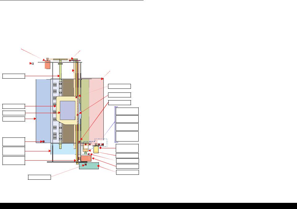
EPSON Stylus Photo RX680/RX685/RX690 |
Revision A |
2.1 Overview
This section describes the operating principles of the Stylus Photo RX680/RX685/ RX690 mechanism and Electrical Circuit Boards.
2.1.1 Printer Mechanism
The main structure of printer mechanism and the motors/sensors in each mechanism are shown in the following figure.
For Sensors names, See Table 2-1. "List of motors and sensors" (p26).
|
|
PF Motor |
|
|
|
|
PF Encoder |
|
|
|
|
|
|
|
|
|
|
|
|
|
|
|
|
|
|
|
|
|
|
|
|
|
|
|
|
|
|
|
|
|
Cover Open |
|
|
|
|
|
|
|
|
|
|
|
|
Sensor |
|
|
|
|
|
|
|
|
|
|
|
|
|
|
|
|
|
|
|
|
|
|
|
|
|
PF Roller |
|
|
|
|
|
|
|
|
ASF Assy |
|
|
|
|
|
|
|
|
|
|
|
|||
|
|
|
|
|
|
|
|
|
|
|
|
|
Eject Roller
|
|
|
PW Sensor |
|
|
|
|
CR Encoder |
|
CR Assy |
|
|
PE Sensor |
|
|
|
(1) Rear ASF |
||
Printhead |
|
|
||
|
|
Position Sensor |
||
Eject Frame |
|
|
(2) Rear ASF |
|
|
|
Home Sensor |
||
|
|
|
||
|
|
|
(3) Duplex Unit |
|
|
|
|
Sensor |
|
|
|
|
(4) Front ASF |
|
|
|
|
Retard Home |
|
CD-R Guide |
|
(3) |
Sensor |
|
Sensor |
|
(4) |
||
(1) |
(2) |
ASF Sub |
||
Ink System |
||||
|
|
Motor |
||
Assy |
|
|
ASF Motor |
|
CR Guide |
|
|
||
|
|
ASF Encoder |
||
Shaft |
|
|
||
|
|
CR Motor |
||
|
|
|
||
|
|
|
APG Assy |
|
|
APG Sensor |
|
|
Figure 2-1. Printer mechanism overview
2.1.2 Motors and Sensors
The following table shows the list of the motors and sensors. And the layout of the sensors and motors is shown on the following page.
Table 2-1. List of motors and sensors
Mechanism Names |
Motors/Sensors |
Ref.* |
||
Printhead (p.28) |
|
--- |
||
|
|
|
|
|
|
|
CR Motor (p.28) |
A |
|
Carriage Mechanism (p.28) |
CR Encoder (p.28) |
1 |
||
|
|
|||
PW Sensor (p.29) |
2 |
|||
|
|
|||
|
|
Cover Open Sensor (CO Sensor) (p.29) |
3 |
|
APG Mechanism (p.30) |
APG Phase Sensor (p.30) |
4 |
||
Paper Loading/Feeding |
PF motor (p.34) |
B |
||
|
|
|||
PF encoder (p.34) |
5 |
|||
Mechanism (p.33) |
||||
PE sensor (p.34) |
6 |
|||
|
|
|||
|
|
|
||
CD-R Mechanism (p.45) |
CDR mode sensor (p.45) |
7 |
||
|
|
ASF motor (p.34) |
C |
|
|
|
|
|
|
|
|
ASF Encoder (p.35) |
8 |
|
Paper Loading/Feeding |
ASF Sub motor (p.35) |
D |
||
Mechanism (p.33) |
Front ASF retard home sensor (FP sensor) (p.35) |
9 |
||
|
|
Rear ASF phase sensor (RP sensor) (p.35) |
10 |
|
|
|
|
|
|
|
|
Rear ASF home sensor (RH sensor) (p.36) |
11 |
|
Duplex Print Unit (p.42) |
Duplex unit sensor (DP sensor) (p.36) |
12 |
||
|
|
|
||
Ink System (p.49) |
|
--- |
||
Note *: |
The alphabet or the number listed in the “Ref.” column indicates the position of the |
|||
|
corresponding sensor or motor in Figure 2-2 or Figure 2-3 on the next page. |
|||
OPERATING PRINCIPLES |
Overview |
26 |

EPSON Stylus Photo RX680/RX685/RX690 |
Revision A |
6 
 1
1
2


 3
3


7
5 
B 
Figure 2-2. Motors/sensors layout (front side)
10
11
A


 D
D


12
C
4 


 9
9
8
Figure 2-3. Motors/sensors layout (rear side)
Scanner Carriage Unit
CR Motor
CR encoder
Figure 2-4. Motors/sensors layout (scanner unit)
OPERATING PRINCIPLES |
Overview |
27 |
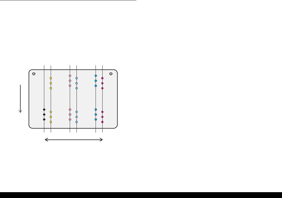
EPSON Stylus Photo RX680/RX685/RX690 |
Revision A |
2.2 Printer Mechanism Operating Principles
2.2.1 Printhead
Print method |
: On-demand ink jet (F-Mach Turbo 2 head) |
||
Nozzle layout |
|
|
|
|
|
|
|
|
Colors |
|
Bk, C, M, Y, Lc, Lm (6 colors) |
|
|
|
|
|
Number of nozzles |
540 nozzles (90 Nozzles for each colors x 6 |
|
|
columns) |
||
|
|
|
|
|
|
|
|
|
Nozzle pitch |
0.282mm (1/90 inch), cross-layout |
|
|
|
|
|
The nozzle layout when viewed from the back surface of the Printhead is shown below.
A#90
A#89
A#88
Paper Feed
Direction
A#3
A#2
A#1
B#90 |
C#90 |
D#90 |
E#90 |
F#90 |
B#89 |
C#89 |
D#89 |
E#89 |
F#89 |
B#88 C#88 |
D#88 E#88 |
F#88 |
||
B#3 |
C#3 |
D#3 |
E#3 |
F#3 |
|
C#2 |
E#2 |
||||
B#2 |
D#2 |
F#2 |
|||
C#1 |
E#1 |
||||
B#1 |
D#1 |
F#1 |
|||
|
|
Carriage Moving Direction
Figure 2-5. Nozzle layout
2.2.2 Carriage Mechanism
The Carriage mechanism consists of the CR motor, Timing belt, Driven pulley, CR guide shaft, Carriage unit, CR scale etc.
2.2.2.1 CR Motor
The CR motor is DC motor (with brushes) and it is controlled by positional/speed information obtained by means of the CR encoder.
Since the DC motor is used, the motor may generate a excessive heat in continuous operations. To avoid this, whether the motor is driven or not, a heating value is calculated at regular intervals to monitor the motor temperature while the power is ON. When the motor temperature exceeds a specified value, the operation is forcibly paused for a specified period of time.
|
|
Table 2-2. CR motor specifications |
|
|
|
|
|
|
Item |
|
Specifications |
Type |
|
DC motor with brushes (Mabuchi RS445PD-16175BR) |
|
Voltage |
|
42V (direct voltage) ± 5% (voltage applied to driver) |
|
|
|
|
|
|
Armature resistance |
|
19.7Ω ± 10% |
Feature |
Inductance |
|
11.6 mH (1kHz) |
|
Rotor inertia |
|
16.2 gcm2 |
Drive Method |
|
PWM, constant-current chopping |
|
Driver |
|
A6651 (Allegro company product) |
|
2.2.2.2 CR Encoder
|
Table 2-3. CR encoder specifications |
|
|
|
|
Item |
Specifications |
|
Power supply voltages |
3.3VDC ± 5% |
|
Output waveform |
Phase A, phase B channel digital output (TTL) |
|
|
|
|
Output level |
High output voltage: 2.4VDC (min.) |
|
Low output voltage: 0.6VDC (max.) |
||
|
||
Resolution |
180 pulses/inch |
|
|
|
|
Signal detection section |
Transmissive photo interrupter |
OPERATING PRINCIPLES |
Printer Mechanism Operating Principles |
28 |
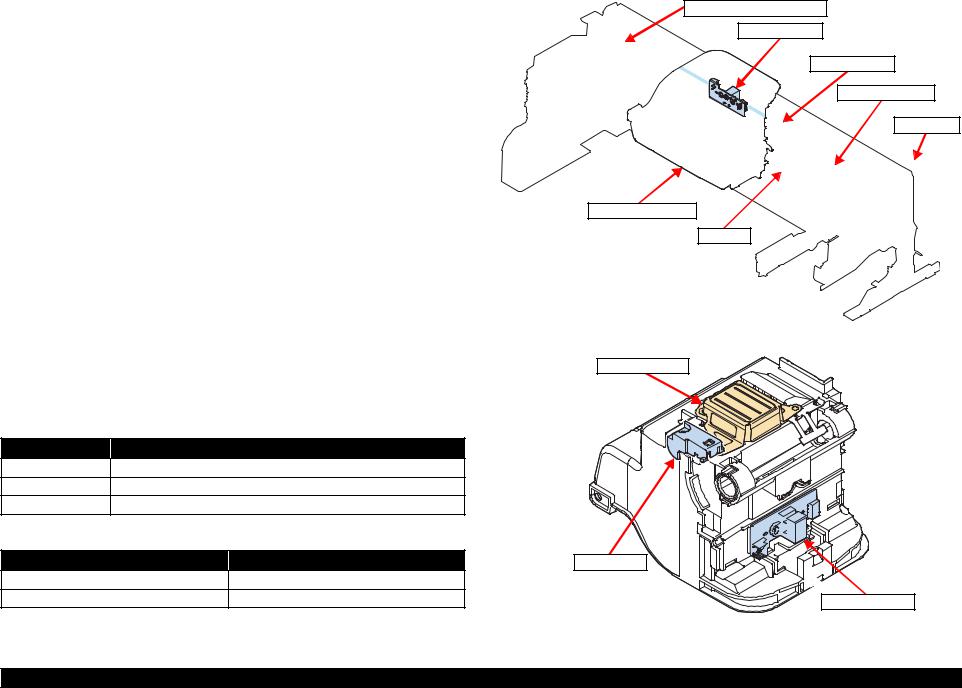
EPSON Stylus Photo RX680/RX685/RX690 |
Revision A |
2.2.2.3 PW Sensor
Detection items
Detects the left, right, top and bottom edges of a cut sheet.
Detects the CD-R center
Specifications
Item |
Specifications |
Type |
Reflective photo interrupter (TOSHIBA S7K95) |
Power supply voltages |
3.3VDC ± 5% |
|
|
Output waveform |
1 channel analogue output |
Result output
Detected state |
Output |
Paper Present |
0V (reference value) |
|
|
Paper Absent |
3.3V (reference value) |
2.2.2.4 Cover Open Sensor (CO Sensor)
When the Cover Open sensor detects that the scanner unit is open, the operation of the carriage is stopped to prevent users from getting injured. And then cover open error is displayed.
Driven pulley unit
CR encoder
CR scale
Timing belt
CR motor
Carriage unit
CR shaft |
Figure 2-6. Carriage Mechanism
Detection item |
|
|
Printhead |
Detects the cover (scanner unit) open/close |
|
||
Specifications |
|
|
|
Item |
|
Specifications |
|
Type |
Mechanical contact points (Mik Denshi MPU10980MMB0) |
|
|
Power supply voltages |
3.3VDC ± 5% |
|
|
Output waveform |
1 channel analogue output |
|
|
Result outputs |
|
|
|
Detected state |
Output |
PW sensor |
|
Cover open |
2.4V or more |
|
|
Cover close |
0.4V or less |
CR encoder |
|
Figure 2-7. Bottom of Carriage Unit
OPERATING PRINCIPLES |
Printer Mechanism Operating Principles |
29 |
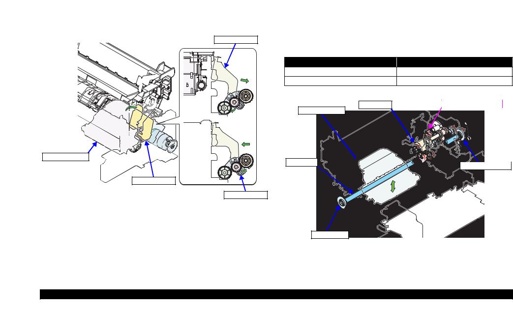
EPSON Stylus Photo RX680/RX685/RX690 |
Revision A |
2.2.3 APG Mechanism
APG mechanism is provided to change the platen gap (PG) automatically within five settings using the driving force of the ASF motor.
To drive the APG mechanism for changing the platen gap, the carriage is moved to its home position to release the change lever, and then the forced clutch is switched to the Ink system/APG drive side.
Change lever
Carriage Assy
Change lever
Forced clutch
Figure 2-8. Switching of Forced Clutch (APG)
Also the APG mechanism is interlocked with CDR guide mechanism. When the platen gap is set to the CDR guide position, the driving force is transmitted to the CDR guide.
See “2.2.5.2 CDR Guide Auto Switching Operation” (p.45).
The next section describes the components of APG mechanism.
2.2.3.1 APG Phase Sensor
Detection item
Detects the PG position
Specifications
Item |
Specifications |
Type |
Transmissive photo interrupter (TOSHIBATLP1243(C8)) |
Power supply voltages |
3.3VDC ± 5% |
Output waveform |
1 channel analogue output |
Result output
Detected state |
Output |
In PG position |
2.4V or more |
Out of PG position |
0.4V or less |
ASF motor |
APG phase sensor |
Carriage Assy
CR shaft 


 Right PG cam
Left PG cam
Figure 2-9. APG mechanism
OPERATING PRINCIPLES |
Printer Mechanism Operating Principles |
30 |

EPSON Stylus Photo RX680/RX685/RX690 Revision A
2.2.3.2 APG Driving Path
A
The driving path of ASF motor to drive APG is shown below.
7. Combination gear 17.6, 11.2A
ASF motor
1. Spur gear 18.5 (Forced clutch) |
|
8. Combination gear 16, 12.8 |
10. Combination gear 17.6, 11.2B |
|
|
|
|
2. Combination gear 24.5, 9.6 |
5. APG Planetary gear (Spur gear 9.6) |
9. Spur gear 22.4 |
11. Flag combination gear 40.8,36 |
3. Spur gear 11.2 (I/S) |
6. Transmissive combination gear 20.8, 11.2 |
Right PG cam |
APG phase sensor |
|
|
||
4. Spur gear 27.2 (I/S) |
To A |
Flowchart 2-2. ASF motor driving path (APG) (2) |
|
|
|
||
APG phase sensor |
11. Flag combination gear 40.8,36 |
APG Assy |
Flowchart 2-1. ASF motor driving path (APG) (1)
5. APG Planetary gear (Spur gear 9.6) |
APG Assy |
6. Transmissive combination gear (Transmits the driving force to APG)
5 

6
4
1 
6. Transmissive |
11 |
|
8 |
combination gear |
|
|
|
(Transmits the |
|
|
9 |
driving force to APG) |
|
|
|
|
|
|
7 |
|
6 |
10 |
Right PG cam |
|
|
||
|
|
|
3 
2 
CR shaft |
Figure 2-11. ASF motor driving path (APG) (2)
Ink system (I/S) |
ASF motor (Rear) |
Figure 2-10. ASF motor driving path (APG) (1)
OPERATING PRINCIPLES |
Printer Mechanism Operating Principles |
31 |
Loading...