


 Loading...
SERVICE MANUAL
Color Inkjet Printer
EPSON Stylus Photo R340/350
SEIJ05008

|
PRECAUTIONS |
Precautionary notations throughout the text are categorized relative to 1) Personal injury and 2) damage to equipment. |
|
DANGER |
Signals a precaution which, if ignored, could result in serious or fatal personal injury. Great caution should be exercised in performing |
|
procedures preceded by DANGER Headings. |
WARNING |
Signals a precaution which, if ignored, could result in damage to equipment. |
The precautionary measures itemized below should always be observed when performing repair/maintenance procedures.
DANGER
1.ALWAYS DISCONNECT THE PRODUCT FROM THE POWER SOURCE AND PERIPHERAL DEVICES PERFORMING ANY MAINTENANCE OR REPAIR PROCEDURES.
2.NO WORK SHOULD BE PERFORMED ON THE UNIT BY PERSONS UNFAMILIAR WITH BASIC SAFETY MEASURES AS DICTATED FOR ALL ELECTRONICS TECHNICIANS IN THEIR LINE OF WORK.
3.WHEN PERFORMING TESTING AS DICTATED WITHIN THIS MANUAL, DO NOT CONNECT THE UNIT TO A POWER SOURCE UNTIL INSTRUCTED TO DO SO. WHEN THE POWER SUPPLY CABLE MUST BE CONNECTED, USE EXTREME CAUTION IN WORKING ON POWER SUPPLY AND OTHER ELECTRONIC COMPONENTS.
4.WHEN DISASSEMBLING OR ASSEMBLING A PRODUCT, MAKE SURE TO WEAR GLOVES TO AVOID INJURIER FROM METAL PARTS WITH SHARP EDGES.
WARNING
1.REPAIRS ON EPSON PRODUCT SHOULD BE PERFORMED ONLY BY AN EPSON CERTIFIED REPAIR TECHNICIAN.
2.MAKE CERTAIN THAT THE SOURCE VOLTAGES IS THE SAME AS THE RATED VOLTAGE, LISTED ON THE SERIAL NUMBER/RATING PLATE. IF THE EPSON PRODUCT HAS A PRIMARY AC RATING DIFFERENT FROM AVAILABLE POWER SOURCE, DO NOT CONNECT IT TO THE POWER SOURCE.
3.ALWAYS VERIFY THAT THE EPSON PRODUCT HAS BEEN DISCONNECTED FROM THE POWER SOURCE BEFORE REMOVING OR REPLACING PRINTED CIRCUIT BOARDS AND/OR INDIVIDUAL CHIPS.
4.IN ORDER TO PROTECT SENSITIVE MICROPROCESSORS AND CIRCUITRY, USE STATIC DISCHARGE EQUIPMENT, SUCH AS ANTI-STATIC WRIST STRAPS, WHEN ACCESSING INTERNAL COMPONENTS.
5.DO NOT REPLACE IMPERFECTLY FUNCTIONING COMPONENTS WITH COMPONENTS WHICH ARE NOT MANUFACTURED BY EPSON. IF SECOND SOURCE IC OR OTHER COMPONENTS WHICH HAVE NOT BEEN APPROVED ARE USED, THEY COULD CAUSE DAMAGE TO THE EPSON PRODUCT, OR COULD VOID THE WARRANTY OFFERED BY EPSON.
6.WHEN USING COMPRESSED AIR PRODUCTS; SUCH AS AIR DUSTER, FOR CLEANING DURING REPAIR AND MAINTENANCE, THE USE OF SUCH PRODUCTS CONTAINING FLAMMABLE GAS IS PROHIBITED.

About This Manual
This manual describes basic functions, theory of electrical and mechanical operations, maintenance and repair procedures of the printer. The instructions and procedures included herein are intended for the experienced repair technicians, and attention should be given to the precautions on the preceding page.
Manual Configuration |
Symbols Used in this Manual |
This manual consists of six chapters and Appendix.
CHAPTER 1. TROUBLESHOOTING
Describes the step-by-step procedures for the troubleshooting.
CHAPTER 2. DISASSEMBLY / ASSEMBLY
Describes the step-by-step procedures for disassembling and assembling the product.
CHAPTER 3. ADJUSTMENT
Provides Epson-approved methods for adjustment.
CHAPTER 4. MAINTENANCE
Provides preventive maintenance procedures and the lists of Epson-approved lubricants and adhesives required for servicing the product.
APPENDIX Provides the following additional information for reference:
•Block Diagram
•Electrical circuit boards schematics
Various symbols are used throughout this manual either to provide additional information on a specific topic or to warn of possible danger present during a procedure or an action. Be aware of all symbols when they are used, and always read NOTE, CAUTION, or WARNING messages.
ADJUSTMENT REQUIRED
CAUTION
Indicates an operating or maintenance procedure, practice or condition that is necessary to keep the product’s quality.
Indicates an operating or maintenance procedure, practice, or condition that, if not strictly observed, could result in damage to, or destruction of, equipment.
CHECK |
May indicate an operating or maintenance procedure, practice or |
POINT |
condition that is necessary to accomplish a task efficiently. It |
|
may also provide additional information that is related to a |
|
specific subject, or comment on the results achieved through a |
|
previous action. |
WARNING |
Indicates an operating or maintenance procedure, practice or |
|
condition that, if not strictly observed, could result in injury or |
|
loss of life. |
|
Indicates that a particular task must be carried out according to a |
|
certain standard after disassembly and before re-assembly, |
|
otherwise the quality of the components in question may be |
|
adversely affected. |

|
|
Revision Status |
Revision |
Issued Date |
Description |
A |
September 16, 2005 |
First Release |

EPSON Stylus Photo R340/350 |
Revision A |
CONTENTS
Chapter 1 Troubleshooting |
|
1.1 Overview . ............................................................................................................. |
8 |
1.2 Warning/Error Messages and Possible Causes . .................................................... |
9 |
1.3 Troubleshooting . ................................................................................................. |
13 |
1.3.1 Troubleshooting by Error Message . .......................................................... |
13 |
1.3.2 Troubleshooting by Observed Symptom . .................................................. |
30 |
Chapter 2 Disassembly and Assembly |
|
2.1 Overview . ........................................................................................................... |
37 |
2.1.1 Precautions .................................................................................................. |
37 |
2.1.2 Tools ........................................................................................................... |
38 |
2.1.3 Work Completion Checklist . ..................................................................... |
38 |
2.2 Ensuring the Quality of Disassembled/Reassembled Printer Mechanism ......... |
39 |
2.3 Disassembly . ....................................................................................................... |
41 |
2.3.1 Removing the Paper Support Assy. . .......................................................... |
42 |
2.3.2 Removing the Left Housing . ...................................................................... |
43 |
2.3.3 Removing the Right Housing . ................................................................... |
44 |
2.3.4 Removing the Panel Board/LCD Module . ................................................. |
46 |
2.3.5 Removing the Upper Housing . .................................................................. |
48 |
2.3.6 Removing the Rear Housing . ..................................................................... |
50 |
2.3.7 Removing the Stacker Assy. . ..................................................................... |
51 |
2.3.8 Removing the Front Paper Guide Porous Pads . ......................................... |
52 |
2.3.9 Removing the Main Board Assy. . .............................................................. |
54 |
2.3.10 Removing the ASF Assy. . ....................................................................... |
58 |
2.3.11 Removing the Shaft Assy. Holder . .......................................................... |
62 |
2.3.12 Removing the CR Motor . ........................................................................ |
66 |
2.3.13 Removing the Print Head . ........................................................................ |
67 |
2.3.14 Removing the Upper Paper Guide . .......................................................... |
69 |
2.3.15 Removing the Printer Mechanism . .......................................................... |
70 |
2.3.16 Removing the Power Supply Assy. . ........................................................ |
74 |
2.3.17 Removing the Waste Ink Pads . ................................................................ |
75 |
2.3.18 Removing the Lower Housing . ................................................................ |
76 |
2.3.19 Removing the APG Assy. . ....................................................................... |
77 |
2.3.20 Removing the Carriage Unit . ................................................................... |
78 |
|
2.3.21 Removing the CD-R Guide Assy. . .......................................................... |
84 |
|
2.3.22 Removing the Ink System . ....................................................................... |
88 |
|
2.3.23 Removing the Front Paper Guide and EJ Roller Assy. . .......................... |
91 |
|
2.3.24 Removing the PF Motor . ......................................................................... |
95 |
|
2.3.25 Removing the PF Roller Assy. . ............................................................... |
96 |
Chapter 3 Adjustment |
|
|
3.1 |
Adjustment Items and Overview . ....................................................................... |
99 |
|
3.1.1 Replacement Part-Based Adjustment Priorities . ....................................... |
99 |
3.2 |
Adjustment by using adjustment program . ....................................................... |
101 |
|
3.2.1 How to judge print samples by using the adjustment program . .............. |
105 |
|
3.2.1.1 Head Angular Adjustment . .............................................................. |
105 |
|
3.2.1.2 Bi-d Adjustment . ............................................................................. |
105 |
|
3.2.1.3 PW Sensor Adjustment/First Dot Adjustment/ |
|
|
Top Margin Adjustment . ................................................................. |
106 |
3.3 |
Adjustment Except Adjustment Program . ........................................................ |
108 |
|
3.3.1 PG Adjustment . ....................................................................................... |
108 |
Chapter 4 Maintenance |
|
|
4.1 |
Overview ........................................................................................................... |
112 |
|
4.1.1 Cleaning .................................................................................................... |
112 |
|
4.1.2 Service Maintenance . ............................................................................... |
112 |
|
4.1.3 Lubrication ................................................................................................ |
113 |
Chapter 5 Appendix |
|
|
5.1 |
Block Diagram . ................................................................................................ |
122 |
5.2 |
Exploded Diagram . ........................................................................................... |
124 |
5.3 |
Electrical Circuits .............................................................................................. |
124 |
6 

C H A P T E R
1
TROUBLESHOOTING
 EPSON Stylus Photo R340/350
1.1 Overview
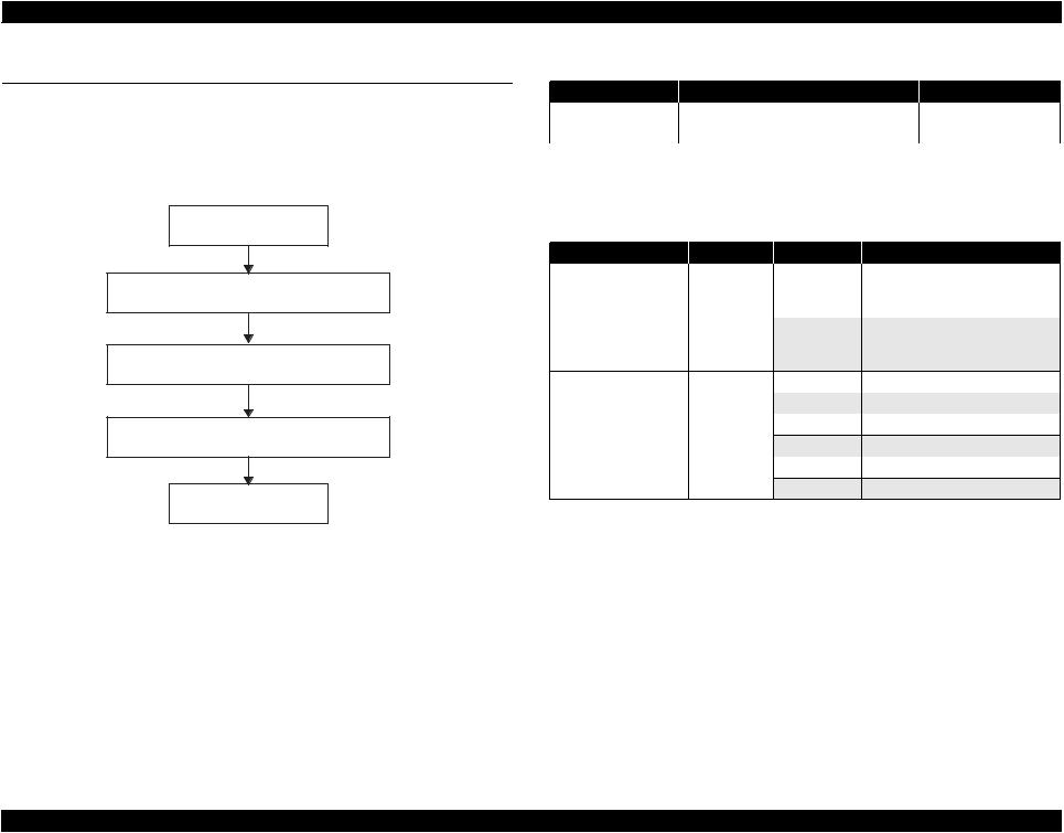
This chapter describes how to troubleshoot problems. Be sure to see the tables provided in this chapter to identify the component that caused the problem you face. And follow the instructions in the table to troubleshoot the component. Also refer to the Motor Wire-Wound Resistor and Sensor Check Points.
Start
Identifying the unit (component) caused the problem
Repairing the unit (component)
Reassembly and adjustment
Finish
Figure 1-1. Troubleshooting Workflow
|
|
|
Revision A |
|
Table 1-1. Motor Wire-Wound Resistor |
|
|
Motor |
Connected Pin No. |
Check Point |
Resistance |
PF Motor |
CN10 |
Pin 1 and 3 |
3.0Ω ±10% |
(ASF/Pump Motor) |
|
Pin 2 and 4 |
(25°C/phase) |
NOTE:As the CR Motor and the APG Motor are DC motors, the resistance between the pins fluctuates. So checking them if they work properly or not is made only by observing them visually (if they rotate or not). It is, however, sometimes difficult to judge, so when in doubt, replace the motor.
Table 1-2. Sensors Check Point
Sensor |
Pin No. |
Check point |
Signal level |
Sensor Statuses |
Tray Sensor |
CN2 |
Pin 1 and 2 |
--- |
Open: |
|
|
|
|
Nipped with Star Wheel |
|
|
|
|
(ASF mode) |
|
|
|
--- |
Close: |
|
|
|
|
Star Wheel is released |
|
|
|
|
(CDR mode) |
CDR Sensor |
CN2 |
Pin 3 and 4 |
--- |
Close: CDR Tray not attached |
|
|
|
--- |
Open: CDR Tray attached |
PG Sensor |
CN3 |
Pin 1 and 2 |
2.4V or more |
Close: PG is set to a preset amount |
|
|
|
0.4V or lower |
Open: Switching PG setting |
PE Sensor |
CN4 |
Pin 1 and 2 |
2.4V or more |
Close: No paper loaded |
|
|
|
0.4V or lower |
Open: Paper is loaded |
Troubleshooting |
Overview |
8 |

EPSON Stylus Photo R340/350 |
Revision A |
1.2 Warning/Error Messages and Possible Causes
The following tables explain the warning/error messages displayed on the LCD and the possible causes of them. The messages are displayed during the printer is performing various sequences (feeding paper, absorbing ink or etc.) or displayed responding to the operations the user made (turning the power on, loading paper or etc.).
Table 1-3. LCD Error Messages and Possible Causes
LCD Messages |
Printer Condition |
Possible Causes |
Recovery from Errors |
Reference |
--- |
Communication error |
A communication error between the host computer and |
|
|
the printer occurred. |
(Background of the ink-low status ink |
The remaining amount of |
This occurs when consumed amount of ink reached 90%. |
cartridge icon is displayed in gray) |
ink is low. |
|
|
|
[Caution] |
|
|
The printer can continue printing operation even after the |
|
|
warning message is displayed on the STM3 screen. |
|
|
However, the printer cannot run a head cleaning. |
No ink cartridge. Set ink cartridge. |
Ink related message 1* |
|
[BK](T0481) |
[M](T0483) |
(No ink cartridge) |
[C](T0482) |
[LM](T0486) |
|
[LC](T0485) |
[Y](T0484) |
|
Ink out. Replace the following ink |
Ink related message 5* |
|
cartridge. |
|
(Ink Out) |
[BK](T0481) |
[M](T0483) |
|
[C](T0482) |
[LM](T0486) |
|
[LC](T0485) |
[Y](T0484) |
|
Ink cartridges are not installed or not installed properly.
Occurs in the following conditions:
•The consumed ink amount reached 100%.
•Ink cartridge failure
[Caution]
The ink cartridge detected as “Ink out” is not totally empty. It still has some amount of ink. This prevents Print Head from damaging by printing without ink.
Replace the ink cartridge. For best results, |
Ink related message 7* |
Reading and writing of the CSIC information of the ink |
|
use genuine EPSON ink. |
(Ink cartridge failure) |
cartridges could not be performed properly. |
|
[BK](T0481) |
[M](T0483) |
|
|
[C](T0482) |
[LM](T0486) |
|
|
[LC](T0485) |
[Y](T0484) |
|
|
Correctly connect the printer and the computer. |
p.13 |
Replace the ink cartridge(s) with new one(s). |
--- |
Recovers from the error after replacement of ink |
p.15 |
cartridge(s) has completed. [Supplement]
•The message appears within 60 seconds at maximum after the occurrence if no operation has been made during the period.
•The message appears immediately before starting a print job or cleaning.
Replace the ink cartridge(s) with new one(s). |
--- |
Replace the ink cartridge(s) with new one(s). |
p.15 |
NOTE "*" :The ink cartridge codes displayed on the LCD vary according to the model.
Stylus Photo R340 : [BK]T0481,[M]T0483,[C]T0482,[LM]T0486,[LC]T0485,[Y]T0484 Stylus Photo R350 : [BK]T0491,[M]T0493,[C]T0492,[LM]T0496,[LC]T0495,[Y]T0494
Troubleshooting |
Warning/Error Messages and Possible Causes |
9 |

EPSON Stylus Photo R340/350 |
Revision A |
|
Table 1-3. LCD Error Messages and Possible Causes (continued) |
LCD Messages |
Printer Condition |
Possible Causes |
External device is not connected or media |
Backup error |
Occurs in the following conditions: |
is not inserted. Backup canceled. |
(no external connection) |
• An external device is not connected to the printer. |
|
|
• No media is set into the connected external device. |
|
|
• No image is stored on the memory card. |
Insufficient space on the backup device. |
Backup error |
The capacity of the media specified to back up is |
Backup cannot be performed. |
(insufficient capacity) |
insufficient. |
No memory card in slot. Backup canceled. |
Backup error (no card) |
No memory card is inserted into the slot of the printer. |
A printer error occurred. Please see your |
Fatal error |
Occurs in the following conditions: |
manual. |
|
• The Carriage Unit cannot move properly because of |
|
|
an external force exerted on the unit. |
|
|
• The PF Motor cannot operate properly. |
Paper out. Load paper press the Start |
No paper error |
The PE Sensor could not detect the top edge of paper |
button. |
|
during the paper feeding sequence. |
Paper or CD/DVD tray jam or feed error. |
Jam error |
Occurs in the following conditions: |
Press the Start button. If the error does not |
|
• The PE Sensor could not detect the bottom edge of |
clear, reinsert the paper or CD/DVD tray |
|
paper during the paper feeding operation. |
and press the Start button. |
|
• The Tray/CDR Sensor could not detect the bottom |
|
|
|
|
|
edge of CD or DVD during the CD/DVD feeding |
|
|
operation. |
Service required. Parts inside your printer |
Maintenance error |
This error is detected when the amount of the waste |
are at end of their service life. See your |
|
liquid absorbed by the Waste Ink Pads has reached its |
manual for details. |
|
upper limit (when the protection counter has reached its |
|
|
upper limit). |
Bluetooth print adapter cannot be |
BT communications error |
Had no response from the Bluetooth unit when the |
recognized. Please remove and reinstall |
|
printer started the Bluetooth communication. |
the adapter. |
|
|
There is a problem with the IrDA interface. See your manual.
The CD/DVD tray is not set correctly. Reload the tray and press Start to continue.
IrDA communications error |
Had no response from the IrDA unit when the printer |
|
started the infrared data communication. |
CDR error (correct set) |
Occurs when the printer starts to print on a CD or DVD |
|
without the CD/DVD tray attached. |
CDR error (reset request) |
The CD/DVD tray could not be detected properly when |
|
the printer starts to print on a CD or DVD. |
Recovery from Errors |
Reference |
Automatically recovers from the error after a lapse |
--- |
of three seconds. |
|
Automatically recovers from the error after a lapse |
--- |
of three seconds. |
|
Automatically recovers from the error after a lapse |
--- |
of three seconds. |
|
Turn off the Power. |
p.16 |
Press the Start button. The printer recovers from |
p.19 |
the error when paper is fed correctly. |
|
Remove the jammed paper or the CD/DVD tray. |
p.21 |
Replace the Waste Ink Pads and reset the |
--- |
Protector Counter. |
|
Remove the Bluetooth unit and press the OK |
--- |
button. |
|
Remove the IrDA unit. |
--- |
Automatically recovers from the error after a lapse |
--- |
of three seconds. |
|
Automatically recovers from the error after a lapse |
--- |
of three seconds. |
|
Troubleshooting |
Warning/Error Messages and Possible Causes |
10 |

EPSON Stylus Photo R340/350 |
Revision A |
LCD Messages
The CD/DVD guide is open. Close the guide to print on paper.
Paper jam. Load paper and press the Start button. If the error does not clear, repeat the procedure.
The CD/DVD tray is not set correctly. Reload the tray and press Start to continue.
Error in the data. The document may not be printed correctly.
Error in the data. The document cannot be printed.
Cannot recognize the memory card or disk.
The document is too large to print with Bluetooth.
The document is too complex to print with Bluetooth.
Error in the data. The document cannot be printed.
Table 1-3. LCD Error Messages and Possible Causes (continued)
Printer Condition
CDR/DVD guide open
Name card long edge first insertion error
Paper mismatch error
A part of the reference object is broken (BTMIME).
A part of the reference object cannot be buffered (BT-MIME).
XHTML-Print document cannot be decoded (BTMIME).
Insertion of unsupported media
BT File size error
BT designation error
BT structure error
Possible Causes
Displayed in the following conditions:
•The CDR Guide Assy. is opened when the printer started to print on a cut sheet.
•The CDR Guide Assy. is opened during the printer is printing on a cut sheet.
A name card is loaded onto the printer in landscape orientation.
The center of the CD or DVD could not be detected during the CD/DVD print job.
Decoding XHTML print data was made successfully, but failed to obtain all or some reference objects included in the data due to their MIME encode errors.
The printout will result in as follows depending on what type of the missed reference objects are:
•Image objects
Blank areas on where the missed objects are supposed to be printed appear.
•CSS (style sheet) files
Background color and font size appear differently from what you expected.
Decoding XHTML print data was made successfully, but failed to obtain all or some reference objects included in the data due to insufficient memory or the number of the objects exceeded the upper limit.
Failed to decode XHTML data to print due to MIME encode errors, or XHTML-Print is not contained.
Not formatted or not compatible media is inserted.
The specified XHTML-Print data is larger than 100 K bytes.
The specified XHTML-Print data is too complicated (tag setting or etc.) to print.
XHTML-Print data could not be decoded.
Recovery from Errors |
Reference |
Automatically recovers from the error after a lapse |
p.25 |
of three seconds. |
|
Remove the jammed card following the |
p.27 |
instruction displayed on the LCD. |
|
Load media that match the print setting. |
p.28 |
Press any one of the buttons on the printer. |
--- |
Press any one of the buttons on the printer. |
--- |
Press any one of the buttons on the printer. |
--- |
Automatically recovers from the error after a lapse |
--- |
of three seconds. |
|
Press any one of the buttons on the printer. |
--- |
Press any one of the buttons on the printer. |
--- |
Press any one of the buttons on the printer. |
--- |
Troubleshooting |
Warning/Error Messages and Possible Causes |
11 |
EPSON Stylus Photo R340/350 |
|
|
|
Revision A |
|
Table 1-3. LCD Error Messages and Possible Causes (continued) |
|
|
|
LCD Messages |
Printer Condition |
Possible Causes |
Recovery from Errors |
Reference |
No memory card or disk inserted, or it |
Memory card print |
A memory card in which has no image data is inserted. |
cannot be recognized. |
|
|
Cannot recognize the memory card or |
Card insertion |
Cannot recognize the memory card inserted into the |
disk. |
|
printer. |
Cannot recognize the device. |
External device installment |
A not compatible memory device is connected to the port |
|
|
for the external memory devices. |
Automatically recovers from the error after a lapse |
--- |
of three seconds. |
|
Automatically recovers from the error after a lapse |
--- |
of three seconds. |
|
Automatically recovers from the error after a lapse |
--- |
of three seconds. |
|
All photos for the specified layout are selected.
[BK](T0148) [M](T0483) [C](T0482) [LM](T0486) [LC](T0485) [Y](T0484)
The installed ink cartridges differ from the genuine EPSON ink cartridges listed below.
The use of other products may affect your print quality and could result in printer damage. Do you want to continue using the currently installed ink cartridges?
Even if borderless printing has been selected, a white border may still appear on an edge.
Memory card print onto CD/ DVD
Ink related message 3* (wrong model number of ink cartridge)
Borderless expansion
The number of images retrieved from the memory card to print on a CD exceeded the upper limit.
Non-EPSON ink cartridges are installed.
Displayed when “Minimum” is selected for the “Borderless expansion” print setting menu.
Automatically recovers from the error after a lapse |
--- |
of three seconds. |
|
Press the OK button or the Back button. |
--- |
Automatically recovers from the error after a lapse |
--- |
of three seconds. |
|
NOTE "*" :The ink cartridge codes displayed on the LCD vary according to the model.
Stylus Photo R340 : [BK]T0481,[M]T0483,[C]T0482,[LM]T0486,[LC]T0485,[Y]T0484 Stylus Photo R350 : [BK]T0491,[M]T0493,[C]T0492,[LM]T0496,[LC]T0495,[Y]T0494
Troubleshooting |
Warning/Error Messages and Possible Causes |
12 |

EPSON Stylus Photo R340/350 |
Revision A |
1.3 Troubleshooting
Be sure to first check the messages displayed on the LCD or the STM3 screen on a connected computer to identify the cause of the problem quickly. Then troubleshoot the problem following the instructions given in the tables in this section. When any components to be repaired or replaced are found, see Chapter 2 “Disassembly/Reassembly” to correctly reinstall or replace the components.
1.3.1 Troubleshooting by Error Message
Occurrence
Timing
CR Position
•Occurrence Timing:
At power-on
•CR Position: Anywhere
Table 1-4. Troubleshooting of Communication Errors based on Observed Symptom
Symptoms |
Failed Part |
|
Check Point |
Remedies |
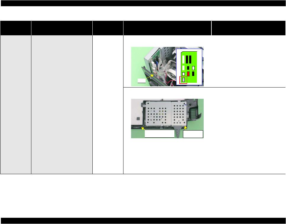
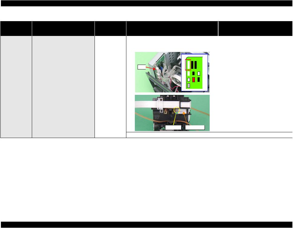
The printer does not start up at all by |
Panel Board/ |
1. Check if the Panel FFC is correctly connected to CN1 on |
1. Correctly connect the Panel FFC to CN1 on |
|
turning the power On. |
Panel FFC |
the Panel Board and CN6 on the Main Board. |
the Panel Board and CN6 on the Main Board. |
|
|
|
CN1 |
Panel Board |
|
 Panel FFC
 CN6
CN6
 Main Board
2.Check if the Panel FFC is damaged.
3.Check if the Panel Board is damaged.
2.Replace the Panel FFC with a new one.
3.Replace the Panel Board with a new one.
Troubleshooting |
Troubleshooting |
13 |
EPSON Stylus Photo R340/350 |
Revision A |
Occurrence
Timing
CR Position
•Occurrence Timing:
At power-on
•CR Position: Anywhere
Table 1-4. Troubleshooting of Communication Errors based on Observed Symptom (continued)
Symptoms |
Failed Part |
Check Point |
Remedies |
||
The printer does not start up at all by |
Power Supply |
1. Check if the Power Supply Board cable is correctly |
1. Correctly connect the Power Supply Board |
||
turning the power On. |
Board Assy. |
connected to CN1 on the Main Board. |
cable to CN1 on the Main Board. |
||
|
|
|
|
|
|
|
|
|
|
|
|
|
|
|
|
|
|
|
|
|
|
|
|
• |
Occurrence |
The initialization sequence at power-on |
|
Timing: |
is performed properly. However, a |
|
During |
communication error occurs (an error |
|
operation |
message is displayed on STM3 screen) |
• |
CR Position: |
when a print job is sent to the printer. |
|
--- |
|
CN1 |
|
2. Check if the Power Supply Board cable or the Power |
2. Replace the Power Supply Assy. with a new |
Supply itself is damaged. |
one. |
|
* If the problem still occurs after performing |
|
the above remedies, replace the Main Board |
|
Assy. with a new one. |
|
|
Power Supply Board |
PowerSupply |
|
|
|
|
Cable |
Assy. |
|
|
USB Cable |
1. |
Check if the printer is correctly connected to the |
1. |
Correctly connect the printer to the computer |
|
|
|
computer with a USB cable. |
|
|
with a USB cable. |
Printer driver |
1. |
Check if the Stylus Photo R340/350 driver is used for |
1. |
Install the Stylus Photo R340/350 printer |
|
|
|
the print job. |
|
|
driver on the computer. |
Main Board |
1. |
Verify that the model name written in the EEPROM on |
1. |
Correct the model name stored on the |
|
|
|
the Main Board is correct. |
|
|
EEPROM using the Market Setting menu in |
|
|
|
|
|
the Adjustment Program. |
Troubleshooting |
Troubleshooting |
14 |
EPSON Stylus Photo R340/350 |
Revision A |
Occurrence
Timing
CR Position
•Occurrence Timing:
At power-on
•CR Position: Home position
Table 1-5. Troubleshooting of Ink-related Errors (Message 1 and 7) based on Observed Symptom
Symptoms |
Failed Part |
Check Point |
Remedies |
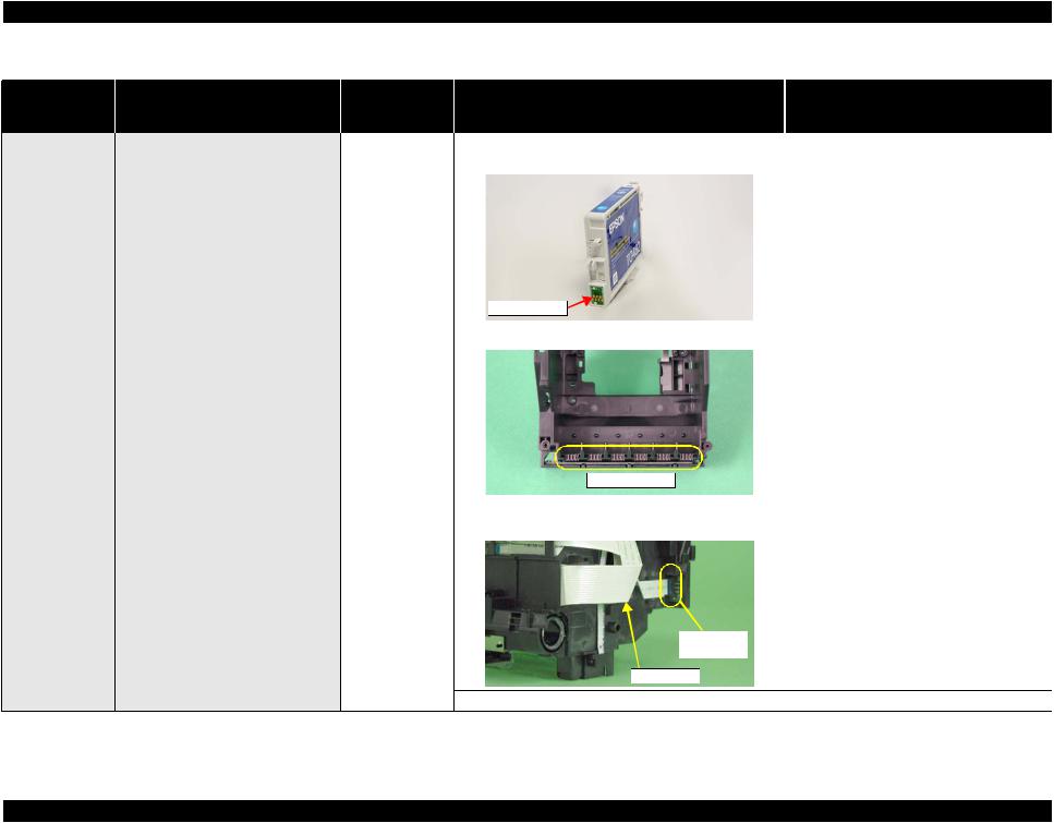
An ink-related error occurs when the |
Ink Cartridge |
1. Check if the memory chip on the cartridge is chipped or |
1. Replace the Ink Cartridge with a new one. |
Carriage returns to the home position. |
|
damaged. |
|
Memory Chip |
|
CSIC Connector 1. Check if the CSIC Connector is damaged. |
1. Replace the Carriage Unit with a new one. |
|
CSIC Connector |
|
CSIC Board |
1. Check if the Head cable is correctly connected to the |
1. Correctly connect the Head cable to the |
|
connector on the CSIC Board. |
connector on the CSIC Board. |
CSIC Board |
|
Connector |
|
Head Cable |
|
2. Check if the CSIC Board is damaged. |
2. Replace the CSIC Board with a new one. |
Troubleshooting |
Troubleshooting |
15 |

EPSON Stylus Photo R340/350 |
Revision A |
Occurrence
Timing
CR Position
•Occurrence Timing:
At power-on
•CR Position:
---
Table 1-6. Troubleshooting of Fatal Errors based on Observed Symptom
Symptoms |
Failed Part |
Check Point |
Remedies |
||
The CR Motor does not start to operate |
CR Motor |
1. Check if the CR Motor cable is correctly connected to |
1. Correctly connect the CR Motor cable to |
||
at all by turning the power On. |
|
CN11 on the Main Board. |
CN11 on the Main Board. |
||
|
|
CN11 |
|
||
|
|
|
|
|
|
|
|
|
|
|
|
|
|
2. |
Check the CR Motor if it works properly. |
2. |
Replace the CR Motor with a new one. |
||||
The Carriage Unit hits against the |
PF Motor |
1. |
Check if the PF Motor cable is correctly connected to |
1. |
Correctly connect the PF Motor cable to |
||||
Change Lever which has inclined toward |
|
|
CN10 on the Main Board. |
|
CN10 on the Main Board. |
||||
the front of the printer at power-on. |
|
|
|
|
|
|
|
|
|
|
|
|
CN10 |
|
|
|
|
|
|
|
|
|
|
|
|
|
|
|
|
|
|
|
|
|
|
|
|
||
|
|
|
|
|
|
|
|
|
|
|
|
|
|
|
|
|
|
|
|
|
|
|
|
|
|
|
|
|
|
|
|
2. |
Check the PF Motor resistance with a tester if it is 3.0 Ω. |
2. |
Replace the PF Motor with a new one. |
||||
|
|
|
See Table 1-1 on page 8. |
|
|
||||
|
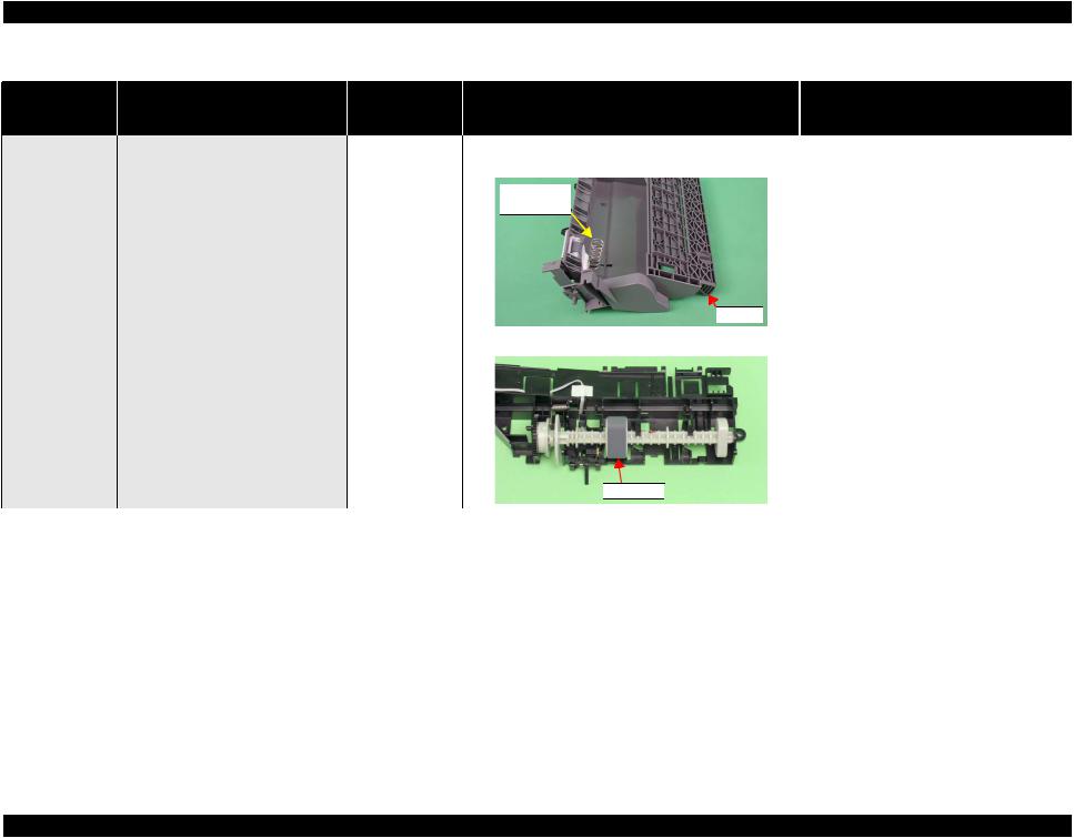
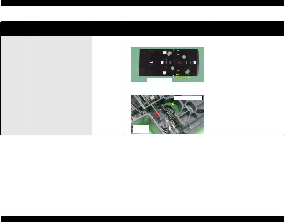
Ink System |
1. |
Check if the Compression Spring 2.36 in the Change |
1. |
Replace the Ink System with a new one. |
||||
|
|
|
Lever has not come off. |
|
|
||||

 Change Lever
Compression
Spring 2.36
Troubleshooting |
Troubleshooting |
16 |
EPSON Stylus Photo R340/350 |
Revision A |
Occurrence
Timing
CR Position
•Occurrence Timing:
At power-on
•CR Position:
---
Table 1-6. Troubleshooting of Fatal Errors based on Observed Symptom (continued)
Symptoms |
Failed Part |
Check Point |
Remedies |
The Carriage Unit hits against the Upper |
Upper Paper Guide 1. Check if the Upper Paper Guide has not come off the |
Paper Guide which has come off the |
Main Frame. |
Main Frame at power-on. |
|
|
Upper Paper Guide |
The Carriage Unit hits against the right |
CR Scale |
1. |
Check if the CR Scale gets dirt. |
side of the Main Frame at power-on. |
|
|
|
|
|
2. |
Check if the CR Scale is damaged. |
|
|
3. |
Check if the CR Scale has come off or it properly runs |
|
|
|
through the slit of the CR Encoder Sensor. |
CR Scale
CR Encoder |
|
Sensor |
Carriage Unit |
1. Install the Upper Paper Guide correctly.
1.Wipe off the dirt completely or replace the CR Scale with a new one if it is stained badly.
2.Replace the CR Scale with a new one.
3.Install the CR Scale correctly.
*If the above does not solve the problem, try the following actions one by one in the order given.
1.Replace the Main Board Assy. with a new one.
2.Replace the CR Encoder Sensor with a new one.
Troubleshooting |
Troubleshooting |
17 |
EPSON Stylus Photo R340/350 |
Revision A |
Occurrence
Timing
CR Position
•Occurrence Timing:
At power-on
•CR Position:
---
Table 1-6. Troubleshooting of Fatal Errors based on Observed Symptom (continued)
Symptoms |
Failed Part |
Check Point |
Remedies |
||
The Carriage Unit hits against the right |
Head Cable |
1. Check if the Head cable is correctly connected to the |
1. Correctly connect the Head cable to the |
||
side of the Main Frame at power-on. |
|
connector on the CR Encoder Sensor Board and CN9 on |
connector on the CR Encoder Sensor Board |
||
|
|
the Main Board. |
and CN9 on the Main Board. |
||
|
|
CN9 |
|
|
|
|
|
|
|
|
|
|
|
|
|
|
|
|
|
|
|
|
|
Connector |
Head Cable |
2. Check if the Head Cable is damaged. |
2. Replace the Head Cable with a new one. |
Troubleshooting |
Troubleshooting |
18 |
EPSON Stylus Photo R340/350 |
Revision A |
Occurrence
Timing
CR Position
•Occurrence Timing: During operation
•CR Position:
---
Table 1-7. Troubleshooting of Paper Out Error based on Observed Symptom
Symptoms |
Failed Part |
Check Point |
Remedies |
The LD Roller shaft rotates to feed |
ASF Assy. |
1. Check the Hopper if it works properly during feeding |
1. Reattach the Compression Spring 2.51 |
paper, but the Hopper does not operate. |
|
paper. |
between the ASF Frame and the Hopper |
|
|
Compression |
properly. |
|
|
|
|
|
|
Spring 2.51 |
|
Hopper |
|
The LD Roller shaft rotates properly, but Shaft Assy. Holder 1. Check the LD Roller surface if it is free of paper dust. |
1. Wipe the paper dust on the LD Roller with a |
the paper is not fed at all. |
clean cloth moistened with alcohol. |
|
* If the problem still occurs after performing |
|
the above remedies, replace the LD Roller |
|
with a new one. |
 LD Roller
Troubleshooting |
Troubleshooting |
19 |
EPSON Stylus Photo R340/350 |
Revision A |
Occurrence
Timing
CR Position
•Occurrence Timing: During operation
•CR Position:
---
Table 1-7. Troubleshooting of Paper Out Error based on Observed Symptom (continued)
Symptoms |
Failed Part |
|
Check Point |
|
Remedies |
The PF Motor drive cannot be |
Shaft Assy. Holder |
1. Check if the Extension Spring 0.143 in the clutch |
1. |
Attach the Extension Spring 0.143 to the |
|
transmitted to the LD Roller Shaft. |
|
|
mechanism has not come off. |
|
clutch mechanism properly. |
|
|
|
Extension Spring 0.143 |
|
|
|
|
|
Clutch Teeth |
|
|
|
|
|
Guide Pin on the LD Roller Shaft |
|
|
|
|
2. |
Check if the Clutch is properly engaged with the LD |
2. |
Properly set the hole of the Clutch onto the |
|
|
|
Roller Shaft with the guide pin on the shaft. |
|
guide pin of the LD Roller Shaft. |
|
|
3. |
Check if the Clutch teeth are damaged. |
3. |
Replace the Shaft Assy. Holder with a new |
|
|
|
|
|
one. |
|
|
4. |
Check if the Clutch is damaged. |
4. |
Replace the Shaft Assy. Holder with a new |
|
|
|
|
|
one. |
|
Ink System |
1. Check if the Compression Spring 2.36 in the Change |
1. |
Replace the Ink System with a new one. |
|
|
|
|
Lever has not come off. |
|
|

 Change Lever
Compression
Spring 2.36
The LD Roller Shaft cannot be set at the |
Ink System |
1. Check if the tip of the Change Lever is damaged. |
1. Replace the Ink System with a new one. |
ASF home position and paper is always |
|
|
|
fed from the ASF Assy. |
|
|
|
Troubleshooting |
Troubleshooting |
20 |
EPSON Stylus Photo R340/350 |
Revision A |
Occurrence
Timing
CR Position
•Occurrence Timing: During operation
•CR Position: Anywhere other than home position
Table 1-8. Troubleshooting of Paper Jam Errors based on Observed Symptom
Symptoms |
Failed Part |
|
Check Point |
|
Remedies |
Paper feeding operation is performed |
ASF Assy. |
1. |
Check if the ASF Assy. is properly installed. |
1. |
Reassemble the ASF Assy. correctly. |
properly, but the paper cannot be sent |
|
2. |
Check the Paper Back Lever if it works properly during |
2. |
Reinstall the Paper Back Lever and the |
into the printer. |
|
||||
|
|
feeding paper. |
|
Torsion Spring 6.45 correctly. |
|
|
|
|
|
Torsion Spring 6.45 
Paper Back Lever |
|
Shaft Assy. Holder 1. Check if the Torsion Spring 0.22 is properly attached. |
1. Reinstall the PE Sensor Lever and the |
|
Torsion Spring 0.22 correctly. |
|
|
Torsion Spring 0.22 |
|
Multi-feed occurs frequently. |
ASF Assy. |
1. Check the Retard Roller Assy. if it works properly during |
1. Attach the Extension Spring 0.45 properly to |
|
|
feeding paper. |
the backside of the Retard Roller Assy. |
Retard
Roller Assy.
Extension
Spring 0.45
Troubleshooting |
Troubleshooting |
21 |
EPSON Stylus Photo R340/350 |
Revision A |
Occurrence
Timing
CR Position
•Occurrence Timing: During operation
•CR Position: Anywhere other than home position
•Occurrence Timing: During operation
•CR Position:
---
Table 1-8. Troubleshooting of Paper Jam Errors based on Observed Symptom (continued)
Symptoms |
Failed Part |
Check Point |
Remedies |
Paper is fed into the printer, but it is |
PE Sensor |
1. Check if the Torsion Spring 0.22 is properly attached. |
1. Engage the PE Sensor Lever and the Torsion |
ejected immediately. |
|
PE Sensor |
Spring 0.22 properly. |
|
|
|
 Torsion Spring 0.22
2. Check if the PE Sensor cable is correctly connected to |
2. Correctly connect the PE Sensor cable to |
||
CN4 on the Main Board. |
CN4 on the Main Board. |
||
CN4 |
|
||
|
|
|
|
|
|
|
|
|
3. |
Check if the PE Sensor is damaged. |
3. |
Replace the PE Sensor with a new one. |
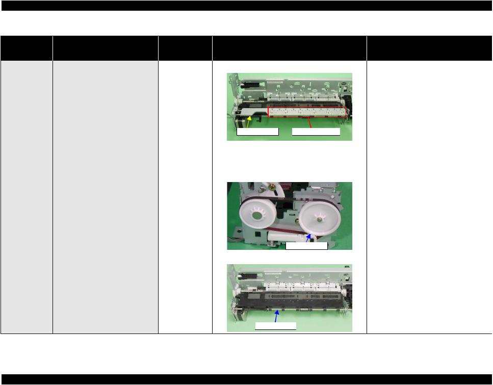
Paper edge cannot go through between |
Front Paper Guide 1. |
Check if the Front Paper Guide Porous Pad is properly |
1. |
Install the Front Paper Guide Porous Pad |
the EJ Roller and the Star Wheels. |
Porous Pad |
installed. |
|
properly. |
 Front Paper Guide Porous Pad
Troubleshooting |
Troubleshooting |
22 |
EPSON Stylus Photo R340/350 |
Revision A |
Occurrence
Timing
CR Position
•Occurrence Timing: During operation
•CR Position:
---
Table 1-8. Troubleshooting of Paper Jam Errors based on Observed Symptom (continued)
Symptoms |
Failed Part |
Check Point |
Remedies |
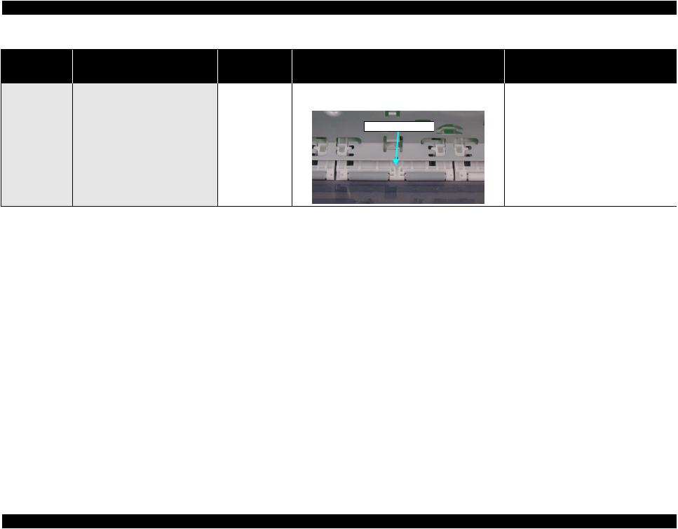
Paper edge cannot go through between |
EJ Frame Assy.* |
1. Check if the Star Wheel Holder has not come off. |
1. Install the Star Wheel Holder correctly. |
the EJ Roller and the Star Wheels. |
|
|
|
|
EJ Frame Assy. |
Star Wheel Holder |
|
|
2. |
Check if the EJ Frame Assy. is properly installed. |
2. |
Install the EJ Frame Assy. correctly. |
|
3. |
Check the EJ Frame Assy. for deformation (if it warped |
3. |
Replace the EJ Frame Assy. with a new one. |
|
|
downward). |
|
|
|
Spur Gear 41.38* 1. |
Check if the Spur Gear 41.38 is damaged. |
1. |
Replace the Spur Gear 41.38 with a new one. |
|
|
Spur Gear 41.38 |
|
EJ Roller Assy.* |
1. Check if the EJ Roller Assy. is properly installed. |
1. Install the EJ Roller Assy. correctly. |
 EJ Roller Assy.
* Jammed paper sometimes contacts with the Print Head and can damage the head.
Troubleshooting |
Troubleshooting |
23 |
EPSON Stylus Photo R340/350 |
Revision A |
Occurrence
Timing
CR Position
•Occurrence Timing: During operation
•CR Position:
---
Table 1-8. Troubleshooting of Paper Jam Errors based on Observed Symptom (continued)
Symptoms |
Failed Part |
Check Point |
Remedies |
Top edge of paper cannot be sent to the |
Upper Paper |
1. Check if the Upper Paper Guide has not come off the |
1. Install the Upper Paper Guide correctly. |
PF Roller. |
Guide* |
Main Frame. |
|
|
|
Upper Paper Guide |
|
* Jammed paper sometimes contacts with the Print Head and can damage the head.
Troubleshooting |
Troubleshooting |
24 |

EPSON Stylus Photo R340/350 |
Revision A |
Occurrence
Timing
CR Position
•Occurrence Timing:
At power-on
•CR Position: Home position
Table 1-9. Troubleshooting of Errors at Opening the CD/DVD Guide based on Observed Symptom
Symptoms |
Failed Part |
Check Point |
Remedies |
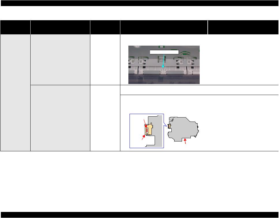
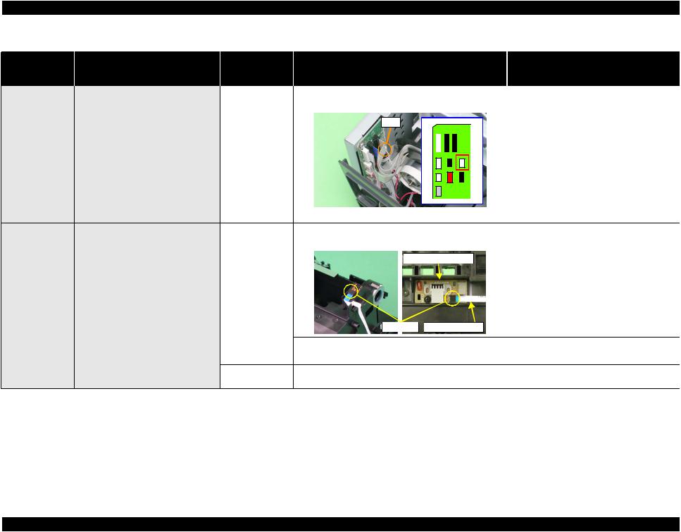
The CD/DVD guide open error occurs at |
Upper Housing |
1. Check if the Tray/CDR Sensor flag on the Upper Housing |
1. Replace the Upper Housing with a new one. |
power-on even though the CDR Guide |
|
is broken. |
|
Assy. is held closed. |
|
|
|
|
|
Flag |
|
Tray/CD-R Sensor 1. Check if the Tray/CDR Sensor cable is correctly |
1. Correctly connect the Tray/CDR Sensor cable |
||
connected to CN2 on the Main Board. |
to CN2 on the Main Board. |
||
|
|
|
|
|
|
|
|
|
|
|
|
|
|
|
|
 CN2
CN2 
2. Check if the Tray/CDR Sensor is damaged.
 Tray/CD-R
 Sensor
3. Check if the Tray/CDR Sensor cable is broken.
2.Replace the Tray/CDR Sensor with a new one.
3.Replace the Tray/CDR Sensor with a new one.
Troubleshooting |
Troubleshooting |
25 |
EPSON Stylus Photo R340/350 |
Revision A |
Occurrence
Timing
CR Position
•Occurrence Timing:
At power-on
•CR Position: Home position
Table 1-9. Troubleshooting of Errors at Opening the CD/DVD Guide based on Observed Symptom (continued)
Symptoms |
Failed Part |
Check Point |
Remedies |
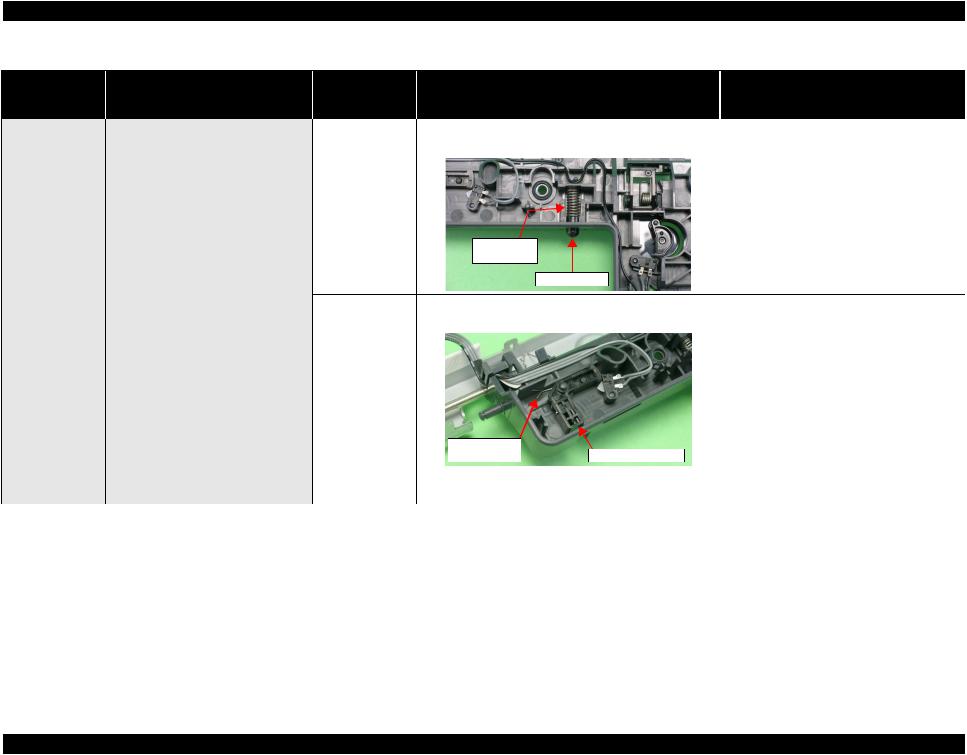
The CD/DVD guide open error occurs at |
Stacker Lock |
1. Check if the Stacker Lock and the Compression Spring |
1. Engage the Stacker Lock and the |
power-on even though the CDR Guide |
|
5.1 are properly engaged. |
Compression Spring 5.1 properly. |
Assy. is held closed. |
|
|
|
Compression
Spring 5.1
Stacker Lock |
|
CDR Sensor Lever 2. Check if the CDR Sensor Lever and the Torsion Spring |
2. Engage the CDR Sensor Lever and the |
4.26 are properly engaged. |
Torsion Spring 4.26 properly. |
|
Torsion Spring |
CDR Sensor Lever |
|
|
4.26 |
|
|
Main Board |
1. Check if any of the elements on the Main Board is |
1. Replace the Main Board with a new one. |
|
|
damaged. |
|
|
Troubleshooting |
Troubleshooting |
26 |
EPSON Stylus Photo R340/350 |
Revision A |
Occurrence
Timing
CR Position
•Occurrence Timing:
At power-on
•CR Position: Anywhere other than home position
•Occurrence Timing: During operation
•CR Position:
---
Table 1-10. Troubleshooting of Name Card Insertion Error based on Observed Symptom
Symptoms |
Failed Part |
Check Point |
Remedies |
||
The name card insertion error occurs at |
PE Sensor |
1. Check if the PE Sensor cable is correctly connected to |
1. Correctly connect the PE Sensor cable to |
||
power-on. |
|
CN4 on the Main Board. |
CN4 on the Main Board. |
||
|
|
CN4 |
|
||
|
|
|
|
|
|
|
|
|
|
|
|
|
|
2. |
Check if the PE Sensor is damaged. |
2. |
Replace the PE Sensor with a new one. |
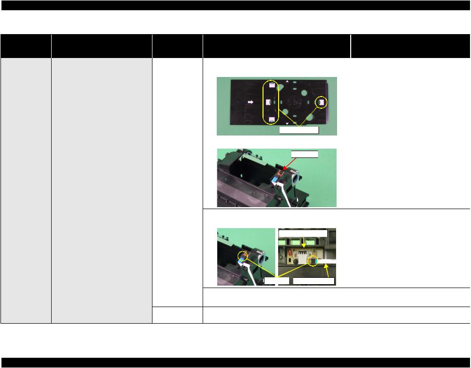
Even though a name card is properly |
PW Sensor |
1. |
Check if the PW Sensor FFC is correctly connected to the |
1. |
Correctly connect the PW Sensor FFC to the |
loaded in landscape orientation, the card |
|
|
connectors on the PW Sensor and the CR Encoder Board. |
|
connectors on the PW Sensor and the CR |
edge cannot be sent to the PF Roller. |
|
|
CR Encoder Board |
|
Encoder Board. |
|
|
|
|
|
|
|
Connector PW Sensor FFC |
|
|
|
2. |
Check the PW Sensor FFC for any damage. |
2. |
Replace the PW Sensor FFC with a new one. |
|
3. |
Check the PW Sensor for any damage. |
3. |
Replace the PW Sensor with a new one. |
Main Board |
1. |
Check if any of the elements on the Main Board is |
1. |
Replace the Main Board with a new one. |
|
|
damaged. |
|
|
Troubleshooting |
Troubleshooting |
27 |
EPSON Stylus Photo R340/350 |
Revision A |
Occurrence
Timing
CR Position
•Occurrence Timing: During operation
•CR Position:
---
Table 1-11. Troubleshooting of CD/DVD Tray Errors based on Observed Symptom
Symptoms |
Failed Part |
Check Point |
Remedies |
A CD/DVD Tray error occurs when |
CD-R Tray |
1. Check if the contact portion of the CDR Tray Sensor on |
1. Replace the CDR Tray Sensor with a new |
attempting to print on a CD or DVD |
|
the CDR Tray is broken. |
one. |
even though the CDR Tray is properly |
|
|
|
attached. |
|
|
|
 Contact Portion
Tray Sensor Lever 2. Check if the Tray Sensor Lever and the Torsion Spring |
2. Engage the Tray Sensor Lever and the |
2.8 are properly engaged. |
Torsion Spring 2.8 properly. |
Tray Sensor Lever |
|
Torsion
Spring 2.8
Troubleshooting |
Troubleshooting |
28 |
EPSON Stylus Photo R340/350 |
Revision A |
Occurrence
Timing
CR Position
•Occurrence Timing: During operation
•CR Position:
---
Table 1-11. Troubleshooting of CD/DVD Tray Errors based on Observed Symptom (continued)
Symptoms |
Failed Part |
Check Point |
Remedies |
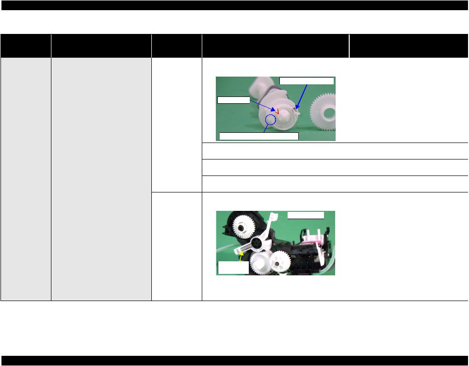
The CDR Tray center detection |
CDR Tray |
1. Check the white marking on the CDR Tray for any paper |
1. Clean the white marking area on the CDR |
sequence is canceled and the CDR Tray |
|
dust or contamination. |
Tray. |
is ejected. |
|
|
|
|
White Marking |
|
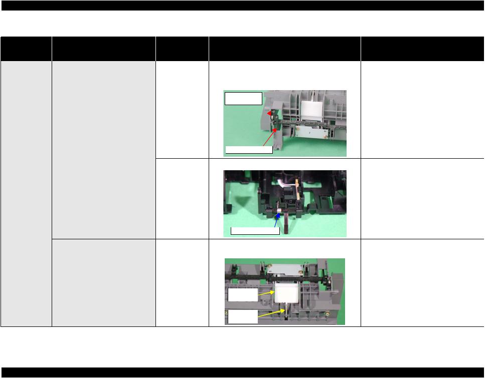
PW Sensor |
1. Check the PW Sensor for paper dust or ink stain. |
1. Clean the surface of the PW Sensor. |
 PW Sensor
2. Check if the PW Sensor FFC is correctly connected to the |
2. Correctly connect the PW Sensor FFC to the |
connectors on the PW Sensor and the CR Encoder Board. |
connectors on the PW Sensor and the CR |
CR Encoder Board |
Encoder Board. |
|
|
|
Connector PW Sensor FFC |
|
|
|
3. |
Check the PW Sensor FFC for any damage. |
3. |
Replace the PW Sensor FFC with a new one. |
|
4. |
Check the PW Sensor for any damage. |
4. |
Replace the PW Sensor with a new one. |
Main Board |
1. |
Check if any of the elements on the Main Board is |
1. |
Replace the Main Board with a new one. |
|
|
damaged. |
|
|
Troubleshooting |
Troubleshooting |
29 |

EPSON Stylus Photo R340/350 |
Revision A |
1.3.2 Troubleshooting by Observed Symptom
Occurrence
Timing
CR Position
•Occurrence Timing: During operation
•CR Position:
---
Table 1-12. Multi-Feed Occurs with No Error Messages displayed on the LCD or STM3 screen
Symptoms |
Failed Part |
Check Point |
Remedies |
Multiple sheets are always fed at a time |
ASF Assy. |
1. Check the Retard Roller Assy. if it works properly during |
1. Attach the Extension Spring 0.45 properly to |
from the ASF Assy., but no error |
|
feeding paper. |
the backside of the Retard Roller Assy. |
messages are displayed on the LCD or |
|
|
|
the STM3 screen. |
|
|
|
Extension
Spring 0.45
2. Check the Paper Back Lever if it works properly during |
2. Reinstall the Paper Back Lever and the |
feeding paper. |
Torsion Spring 6.45 correctly. |
Torsion Spring 6.45 
 Paper Back Lever
Troubleshooting |
Troubleshooting |
30 |

EPSON Stylus Photo R340/350 |
Revision A |
Occurrence
Timing
CR Position
•Occurrence Timing: Anytime
•CR Position: Anywhere
Problems
•Dot missing Mixed colors, Blank pages
Table 1-13. Abnormal Noises are Produced during Operation
Symptoms |
Failed Part |
Check Point |
Remedies |
Printing operations are performed properly, but abnormal noises are produced after turning the power On and during operations.
The bottom of the Carriage Unit comes into contact with the surface of the Front Frame.
Carriage Unit |
1. |
Check if the CR Guide Shaft is properly lubricated. |
Ink System |
1. |
Check if the Change Lever moves smoothly. |
EJ Frame Assy. |
1. |
Check if the EJ Frame Assy. has warped upward. |
1.Wipe off the remaining oil on the CR Guide Shaft and re-lubricate the shaft properly.
1. Replace the Ink System with a new one.
1. Replace the EJ Frame Assy. with a new one.
The Carriage Unit hits against the Upper |
Upper Paper Guide 1. Check if the Upper Paper Guide has not come off the |
1. Install the Upper Paper Guide correctly. |
Paper Guide while the Carriage Unit is |
Main Frame. |
|
moving. |
|
|
Table 1-14. Print Quality Problems
Description |
Failed Part |
Ink cannot be discharged from the Print |
Ink System |
Head to the Cap. |
(Cap Unit) |
Check Point
1.Check the shielding rubber of the Cap Unit for any damage or foreign material.
 Shielding Rubber
2.Check if the Compression Spring 2.53 is properly attached.
Compression |
Spring 2.53 |
Remedies
1.Remove the foreign material from the shielding rubber.
*If the Ink System is damaged, replace it with a new one.
2.Replace the Ink System with a new one.
Troubleshooting |
Troubleshooting |
31 |
Loading...