


Stylus Photo 1400
Table of contents
 Loading...
EPSON Stylus Photo 1400/1410
Color Inkjet Printer
SEIJ06009
SERVICE MANUAL

PRECAUTIONS
Precautionary notations throughout the text are categorized relative to 1) personal injury and 2) damage to equipment.
DANGER Signals a precaution which, if ignored, could result in serious or fatal personal injury.
Great caution should be exercised in performing procedures preceded by DANGER Headings.
WARNING Signals a precaution which, if ignored, could result in damage to equipment.
The precautionary measures itemized below should always be observed when performing repair/maintenance procedures.
DANGER
1. ALWAYS DISCONNECT THE PRODUCT FROM THE POWER SOURCE AND PERIPHERAL DEVICES BEFORE PERFORMING ANY MAINTENANCE OR REPAIR PROCEDURES.
2. NO WORK SHOULD BE PERFORMED ON THE UNIT BY PERSONS UNFAMILIAR WITH BASIC SAFETY MEASURES AS DICTATED FOR ALL ELECTRONICS TECHNICIANS IN
THEIR LINE OF WORK.
3. WHEN PERFORMING TESTING AS DICTATED WITHIN THIS MANUAL, DO NOT CONNECT THE UNIT TO A POWER SOURCE UNTIL INSTRUCTED TO DO SO. WHEN THE
POWER SUPPLY CABLE MUST BE CONNECTED, USE EXTREME CAUTION IN WORKING ON POWER SUPPLY AND OTHER ELECTRONIC COMPONENTS.
4. WHEN DISASSEMBLING OR ASSEMBLING A PRODUCT, MAKE SURE TO WEAR GLOVES TO AVOID INJURIES FROM METAL PARTS WITH SHARP EDGES.
WARNING
1. REPAIRS ON EPSON PRODUCT SHOULD BE PERFORMED ONLY BY AN EPSON CERTIFIED REPAIR TECHNICIAN.
2. MAKE CERTAIN THAT THE SOURCE VOLTAGE IS THE SAME AS THE RATED VOLTAGE, LISTED ON THE SERIAL NUMBER/RATING PLATE. IF THE EPSON PRODUCT HAS
A PRIMARY AC RATING DIFFERENT FROM AVAILABLE POWER SOURCE, DO NOT CONNECT IT TO THE POWER SOURCE.
3. ALWAYS VERIFY THAT THE EPSON PRODUCT HAS BEEN DISCONNECTED FROM THE POWER SOURCE BEFORE REMOVING OR REPLACING PRINTED CIRCUIT BOARDS
AND/OR INDIVIDUAL CHIPS.
4. IN ORDER TO PROTECT SENSITIVE MICROPROCESSORS AND CIRCUITRY, USE STATIC DISCHARGE EQUIPMENT, SUCH AS ANTI-STATIC WRIST STRAPS, WHEN
ACCESSING INTERNAL COMPONENTS.
5. DO NOT REPLACE IMPERFECTLY FUNCTIONING COMPONENTS WITH COMPONENTS WHICH ARE NOT MANUFACTURED BY EPSON. IF SECOND SOURCE IC OR OTHER
COMPONENTS WHICH HAVE NOT BEEN APPROVED ARE USED, THEY COULD CAUSE DAMAGE TO THE EPSON PRODUCT, OR COULD VOID THE WARRANTY OFFERED
BY EPSON.
6. WHEN USING COMPRESSED AIR PRODUCTS; SUCH AS AIR DUSTER, FOR CLEANING DURING REPAIR AND MAINTENANCE, THE USE OF SUCH PRODUCTS CONTAINING
FLAMMABLE GAS IS PROHIBITED.

About This Manual
This manual describes basic functions, theory of electrical and mechanical operations, maintenance, and repair procedures of the printer.
The instructions and procedures included herein are intended for the experienced repair technicians, and attention should be given to the precautions on the preceding page.
Manual Configuration
This manual consists of six chapters and Appendix.
CHAPTER 1. PRODUCT DESCRIPTIONS
Provides a general overview and specifications of the product.
CHAPTER 2. OPERATING PRINCIPLES
Describes the theory of electrical and mechanical operations of the
product.
CHAPTER 3. TROUBLESHOOTING
Describes the step-by-step procedures for the troubleshooting.
CHAPTER 4. DISASSEMBLY / ASSEMBLY
Describes the step-by-step procedures for disassembling and
assembling the product.
CHAPTER 5. ADJUSTMENT
Provides Epson-approved methods for adjustment.
CHAPTER 6. MAINTENANCE
Provides preventive maintenance procedures and the list of Epson-
approved lubricants and adhesives required for servicing the product.
APPENDIX Provides the following additional information for reference:
• Connector summary
• Electric circuit diagrams
Symbols Used in this Manual
Various symbols are used throughout this manual either to provide additional
information on a specific topic or to warn of possible danger present during a
procedure or an action. Be aware of all symbols when they are used, and always read
NOTE, CAUTION, and WARNING messages.
Indicates an operating or maintenance procedure, practice or condition
that, if not strictly observed, could result in injury.
Indicates an operating or maintenance procedure, practice, or condition
that, if not strictly observed, could result in damage to, or destruction of
equipment.
May indicate an operating or maintenance procedure, practice or
condition that is necessary to accomplish a task efficiently. It may also
provide additional information that is related to a specific subject, or
comment on the results achieved through a previous action.
Indicates a product reassembly procedure, practice or condition that
must be executed in accordance with the specified standards to maintain
the product’s quality.
Indicates an operating or maintenance procedure, practice or condition
that must be executed in accordance with the specified standards to
maintain the product’s quality.
W A R N I N G
C A U T I O N
C H E C K
P O I N T
A D J U S T M E N T
R E Q U I R E D

Revision Status
Revision Date of Issue Description
A October 20, 2006 First Release

EPSON Stylus Photo 1400/1410 Revision A
6
Contents
Chapter 1 PRODUCT DESCRIPTION
1.1 Overview ............................................................................................................... 9
1.2 Printing Area ....................................................................................................... 10
1.2.1 Printing Area (Cut sheet, Envelope)........................................................... 11
1.3 PG Setting............................................................................................................ 16
1.4 Printer Function ................................................................................................... 17
1.4.1 Operator Controls ....................................................................................... 17
1.4.2 Buttons........................................................................................................ 17
1.4.3 LED Indicators............................................................................................ 17
1.4.4 Panel Functions........................................................................................... 17
1.4.5 Printer Condition and Panel LED Status .................................................... 18
1.4.6 Errors .......................................................................................................... 19
1.5 Size and Weight................................................................................................... 20
1.6 Accessories .......................................................................................................... 20
Chapter 2 OPERATING PRINCIPLES
2.1 Overview ............................................................................................................. 22
2.2 Printer Mechanism............................................................................................... 22
2.2.1 Carriage Mechanism................................................................................... 23
2.2.2 Printhead Specifications ............................................................................. 26
2.2.3 Paper Feeding Mechanism.......................................................................... 26
2.2.4 Paper Feeding Mechanism.......................................................................... 30
2.2.5 Ink System Mechanism............................................................................... 31
2.2.6 Ink Sequence............................................................................................... 33
2.2.7 Power-On Sequence.................................................................................... 34
2.3 Electrical Circuit Operating Principles................................................................ 35
2.3.1 Power Supply Circuit Operating Principle ................................................. 36
2.3.2 C655 MAIN Circuit Operating Principle ................................................... 37
Chapter 3 TROUBLESHOOTING
3.1 Overview ............................................................................................................. 40
3.1.1 Troubleshooting according to Panel Messages........................................... 40
3.1.2 Troubleshooting based on Observed Faults................................................ 62
Chapter 4 DISASSEMBLY AND ASSEMBLY
4.1 Overview ............................................................................................................. 72
4.1.1 Precautions.................................................................................................. 72
4.1.2 Tools ........................................................................................................... 73
4.1.3 Screws......................................................................................................... 73
4.1.4 Work Completion Checklist ....................................................................... 74
4.1.5 Sharp Metal Edges...................................................................................... 75
4.1.6 Method for making CSIC board removal tool............................................ 75
4.2 Disassembly/Assembly Procedures..................................................................... 76
4.2.1 Removing the Housings.............................................................................. 77
4.2.2 Waste Ink Pad............................................................................................. 83
4.2.3 Front Paper Guide Pad................................................................................ 84
4.2.4 ASF Assy.................................................................................................... 85
4.2.5 Removing the Boards ................................................................................. 89
4.2.6 Disassembling the Printer Mechanism ....................................................... 91
4.2.7 Removing the Motors ............................................................................... 121
4.2.8 Removing the Sensors .............................................................................. 123
Chapter 5 ADJUSTMENT
5.1 Adjustment Items and Overview....................................................................... 128
5.1.1 Servicing Adjustment Item List................................................................ 128
5.1.2 Replacement Part-Based Adjustment Priorities ....................................... 131
5.1.3 Required Adjustment Tools...................................................................... 133
5.2 Adjustment ........................................................................................................ 133
5.2.1 PF Belt Tension Adjustment..................................................................... 133
5.2.2 PG Adjustment ......................................................................................... 135
5.2.3 PF Roller Shaft Center Support Position Adjustment .............................. 140

EPSON Stylus Photo 1400/1410 Revision A
7
Chapter 6 MAINTENANCE
6.1 Overview ........................................................................................................... 145
6.1.1 ROM Replacement ................................................................................... 145
6.1.2 Cleaning.................................................................................................... 145
6.1.3 Service Maintenance................................................................................. 146
6.1.4 Lubrication................................................................................................ 147
Chapter 7 APPENDIX
7.1 Connector Summary.......................................................................................... 154
7.1.1 Connectors and Pin Layouts ..................................................................... 154
7.2 Exploded Diagrams and Parts List .................................................................... 158
7.3 Electrical Circuit Diagrams ............................................................................... 158

CHAPTER
1
PRODUCT DESCRIPTION
EPSON Stylus Photo 1400/1410 Revision A
PRODUCT DESCRIPTION Overview 9
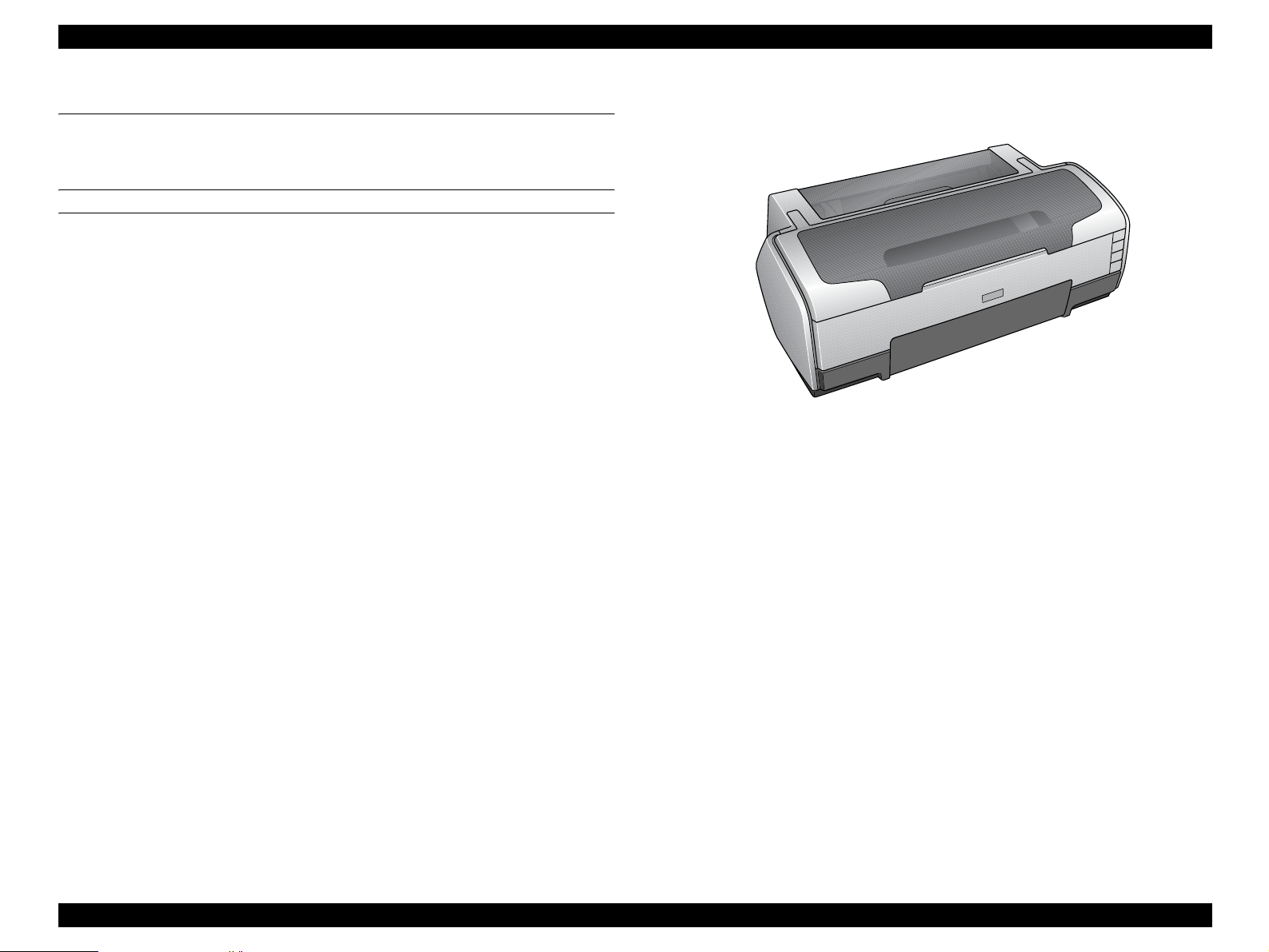
1.1 Overview
EPSON Stylus Photo 1400/1410 is a color inkjet printer designed for a wide range of
users, from home use to office use. The main features of this printer are:
Features
EPSON’s latest dye ink ensures high levels of lightfastness and gasfastness
Six individually replaceable ink cartridges let you print at up to
5760 x 1440 dpi (dots per inch).
Border-free printing up to A3+
High-quality and high-speed printing
CD-R direct printing capability using the CD/DVD tray fed into the front of the printer
ESC/P-R Level-1 command compatible
Prints RGB images transferred from the host devices
Directly prints from PictBridge and an USB Direct Print-enabled digital cameras
Clearly arranged three buttons and three LEDs offer quick, easy operation
Figure 1-1. Product’s External View
EPSON Stylus Photo 1400/1410 Revision A
PRODUCT DESCRIPTION Printing Area 10
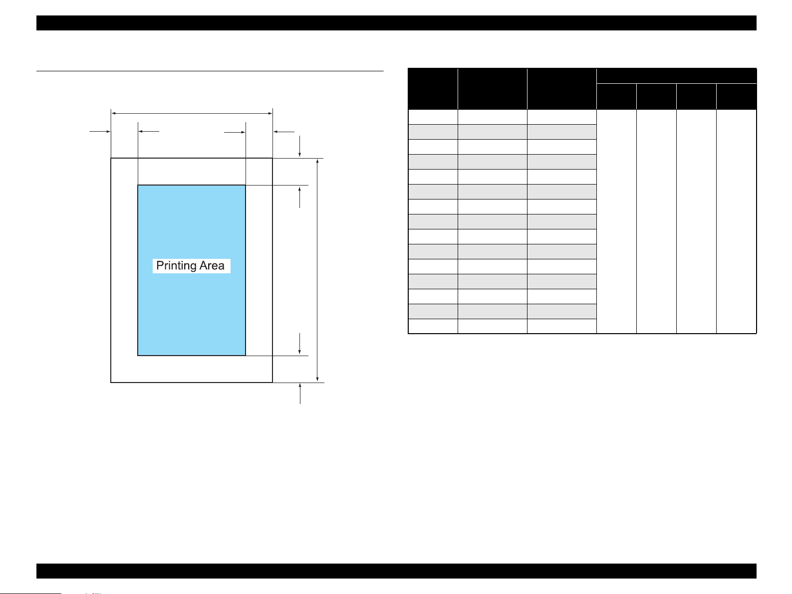
1.2 Printing Area
The printing area for this printer is shown below.
Figure 1-2. Printing Area
Note *1: Bottom margin can be reduced to 3 mm (minimum) by specifying the paper length
via ESC(S command, however, print quality may not be acceptable in the area 3 mm
to 43.3 mm (0.12 in. to 1.7 in.) from the bottom edge. When paper length is not
specified, the bottom margin will be 3 mm or more.
*2: EAI models only.
*3: Except for EAI models.
Note 1: Under the specific conditions, margins on all sides can be reduced to 0 mm.
2: Under the specific conditions, margins on both left and right sides can be reduced to
0 mm.
PW
LM RM
TM
BM
P
L
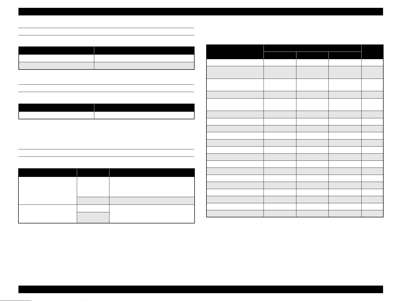
Table 1-1. Printing Area
Paper Size
Width
(PW)
Length
(PL)
Margin
Left
(LM)
Right
(RM)
Top
(TM)
Bottom
(BM)
*1
A3+ 329 mm (12.9 in.) 483 mm (19 in.)
3 mm
(0.12 in.)
or more
3 mm
(0.12 in.)
or more
3 mm
(0.12 in.)
or more
3 mm
(0.12 in.)
or more
A3 297 mm (11.7 in.) 420 mm (16.5 in.)
US B
*2
279.4 mm (11 in.) 431.8 mm (17 in.)
B4 257 mm (10.1 in.) 364 mm (14.3 in.)
US Legal 216 mm (8.5 in.) 356 mm (14 in.)
US Letter 216 mm (8.5 in.) 279 mm (10.9 in.)
A4 210 mm (8.3 in.) 297 mm (11.7 in.)
B5
*3
182 mm (7.2 in.) 257 mm (10.1 in.)
A5
*3
148 mm (5.8 in.) 210 mm (8.3 in.)
Half letter
*2
139.7 mm (5.5 in.) 215.9 mm (8.5 in.)
A6 105 mm (4.1 in.) 148 mm (5.8 in.)
8x10
*2
203.2 mm (8 in.) 254 mm (10 in.)
5x7 127 mm (5 in.) 262 mm (10.3 in.)
4x6 101.6 mm (4 in.) 152.4 mm (6 in.)
16:9 Wide 101.6 mm (4 in.)
180.6 mm (7.1 in.)
EPSON Stylus Photo 1400/1410 Revision A
PRODUCT DESCRIPTION Printing Area 11
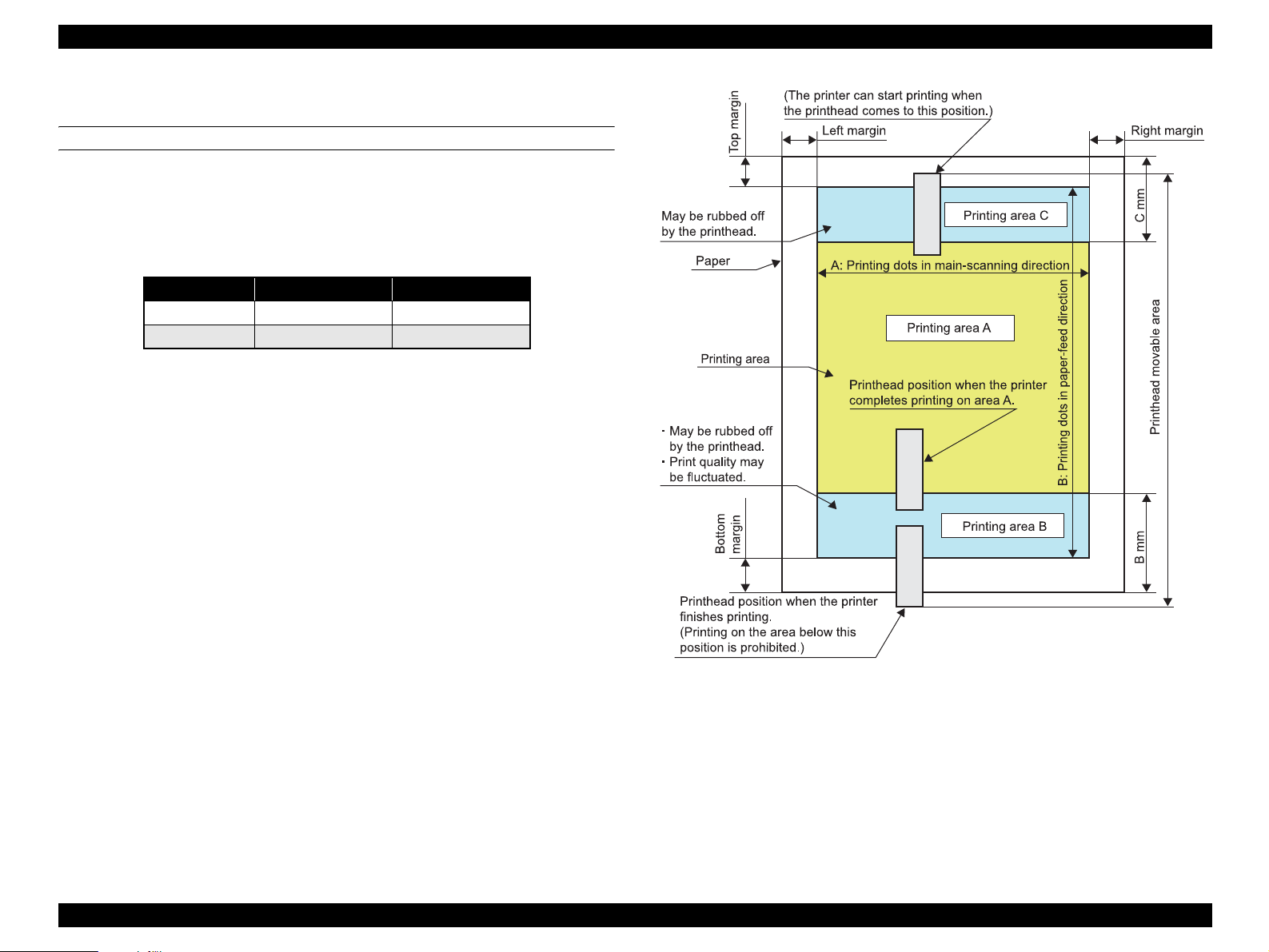
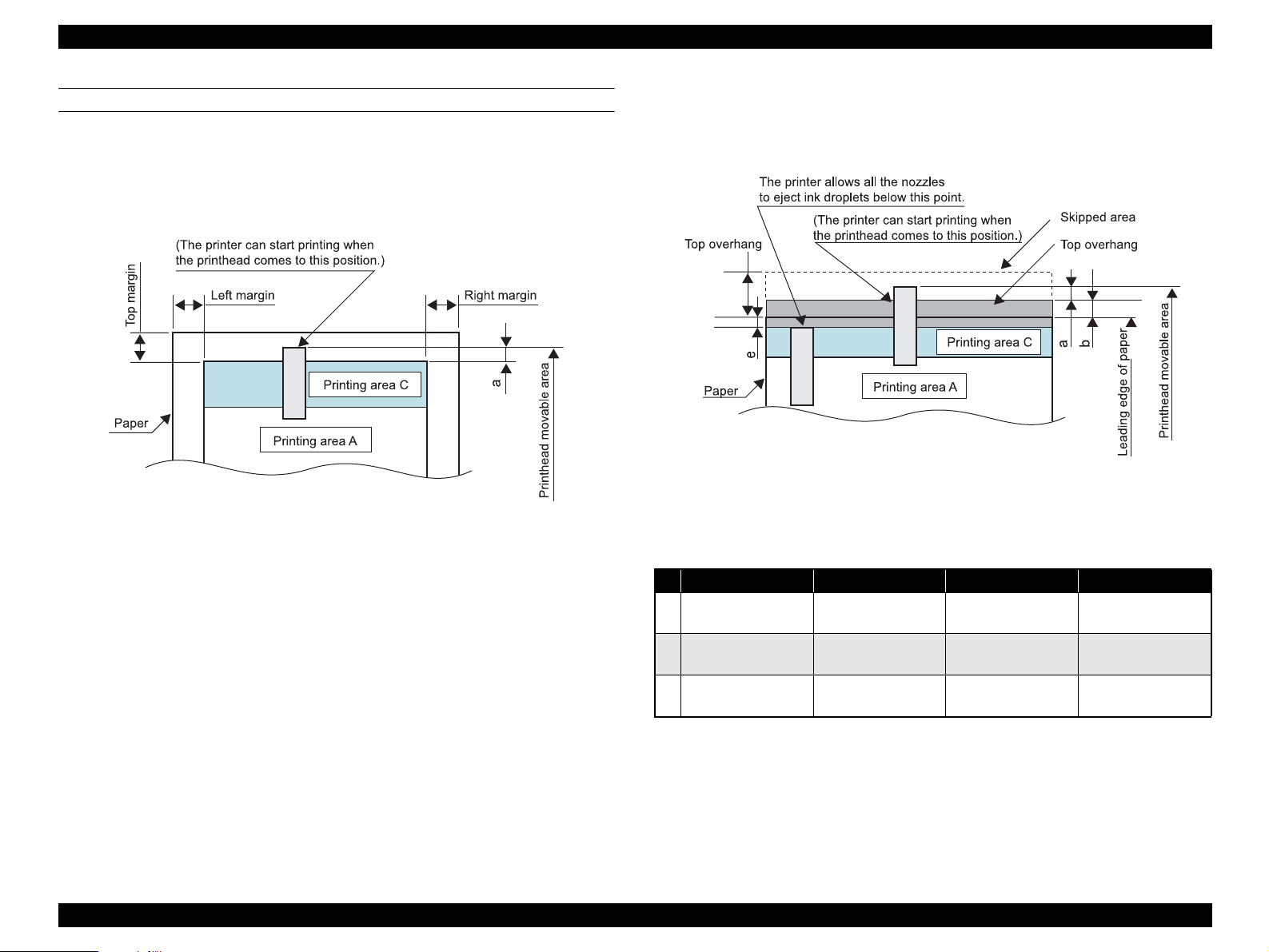
1.2.1 Printing Area (Cut sheet, Envelope)
Printing area (Print with borders)
Figure 1-3 shows the printing area (A, B, and C) for cut sheet and envelope.
Print quality may be fluctuated in printing area B, and both printing area B and C are
subject to being rubbed off by the Printhead. Margins on all sides are designed to
prevent the printed images from running off the paper.
Figure 1-3. Printing Area (Print with Borders)
Table 1-2. Printing Area
Paper Type Printing Area B Printing Area C
Cut sheet 43.3 mm (1.7 in.) 40.1 mm (1.58 in.)
Envelope 20 mm (0.79 in.) 40.1 mm (1.58 in.)

EPSON Stylus Photo 1400/1410 Revision A
PRODUCT DESCRIPTION Printing Area 12
Printing area (Border-free printing)
Figure 1-4 shows the printing area (A, B, C, and D) when border-free printing is
selected. Printing area D is supposed to be trimmed and may not be printed.
Border-free printing is available on the following media sizes:
Paper width
54, 55, 89, 100, 127, 210 mm
4, 5, 8, 8.5 inch
Figure 1-4. Printing Area (Border-free Printing)
Table 1-3. Printing Area Off the Paper Edges
Margin 4x6 A4/Letter or smaller A3+ or smaller
Top 19/360” (1.34 mm) 42/360” (2.96 mm) 42/360” (2.96 mm)
Left/ Right 36/360” (2.54 mm) 36/360” (2.54 mm) 49/360” (3.46 mm)
Bottom 36/360” (2.54 mm.) 57/360” (4.02 mm) 64/360” (4.52 mm)
*: 2.96 mm (168/1440”)
Length from leading edge of paper reference point to paper feed standby position
EPSON Stylus Photo 1400/1410 Revision A
PRODUCT DESCRIPTION Printing Area 13
Printhead movable area
Figure 1-5 to Figure 1-9 show movable area of the printhead in relation to the printing
area in sub-scanning (paper-feed) direction.
Top edge
(1) When top margin is set to 3 mm (0.12 in.)
Figure 1-5. Printhead Movable Area (3-mm Top Margin)
(2) When top margin is set to 0 mm
During printing the area indicated by the arrows a in the figure, some nozzles
are controlled not to eject ink droplets. When #1 nozzle passes through
printing area C, the control is cleared.
Figure 1-6. Printhead Movable Area (0-mm Top Margin)
Details on the length that the printhead moves off the paper edges (a), printing area off
the paper edges (b), and points where the nozzle control is cleared (e) are shown in the
table below.
Note : As for e values, areas off the paper edges are indicated by negative values.
Nozzle positions for printing off the paper edge: #1 to #18 (18 nozzles in total)
Nozzle pitch for printing off the paper edge: 68/360 (4.80mm)
a = Not defined
4x6 (Hi-speed) 4x6
A4/Letter or smaller A3+ or smaller
a
68/360”
(4.80 mm/0.19 in.)
68/360”
(4.80 mm/0.19 in.)
68/360”
(4.80 mm/0.19 in.)
68/360”
(4.80 mm/0.19 in.)
b
13/360”
(0.92 mm/0.04 in.)
9/360”
(0.64 mm/0.03 in.)
9/360”
(0.64 mm0.03 in.)
9/360”
(0.64 mm0.03 in.)
e
-55/360”
(-3.88 mm/-0.15 in.)
-50/360”
(-3.52 mm/-0.14 in.)
-46/360”
(-3.25 mm/-0.13 in.)
-38/360”
(-2.68 mm/-0.1 in.)
EPSON Stylus Photo 1400/1410 Revision A
PRODUCT DESCRIPTION Printing Area 14
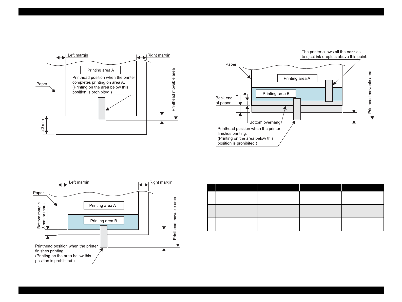
Bottom edge
(1) When bottom margin is set to 20 mm (0.79 in.)
(For envelope/when bottom margin is set automatically)
Figure 1-7. Printhead Movable Area (20-mm Bottom Margin)
(2) When bottom margin is set to 3 to 20 mm (0.12 to 0.79 in.)
Figure 1-8. Printhead Movable Area (3-mm Bottom Margin)
(3) When bottom margin is set to 0 mm
During printing the area indicated by the arrows c in the figure, some nozzles
are controlled not to eject ink droplets.
Figure 1-9. Printhead Movable Area (0-mm bottom margin)
Details on the length that the printhead moves off the paper edges (a), printing area off
the paper edges (b), and points where the nozzle control is cleared (e) are shown in the
table below.
Note : As for e values, areas off the paper edges are indicated by negative values.
Nozzle positions for printing off the paper edge: #73 to #90 (18 nozzles in total)
Nozzle pitch for printing off the paper edge: 68/360 (4.80mm)
C
c = 33/360” (2.33 mm)
For reference: C= 20 mm - (length from upstream nozzle position to nip position + its
variations (simple addition) + variations in the bottom area accumulated from the top)
c
c = Not defined
4x6 (Hi-speed) 4x6
A4/Letter or smaller A3+ or smaller
a
68/360”
(4.80 mm/0.19 in.)
68/360”
(4.80 mm/0.19 in.)
68/360”
(4.80 mm/0.19 in.)
68/360”
(4.80 mm/0.19 in.)
b
27/360”
(1.91 mm/0.07 in.)
30/360”
(2.12 mm/0.08 in.)
39/360”
(2.75 mm/0.10 in.)
55/360”
(3.88 mm/0.16 in.)
e
-41/360”
(-2.89 mm/-0.11 in.)
-44/360”
(-3.10 mm/-0.12 in.)
-38/360”
(-2.68 mm/-0.1 in.)
-28/360”
(-1.98 mm/-0.08 in.)
c
EPSON Stylus Photo 1400/1410 Revision A
PRODUCT DESCRIPTION Printing Area 15
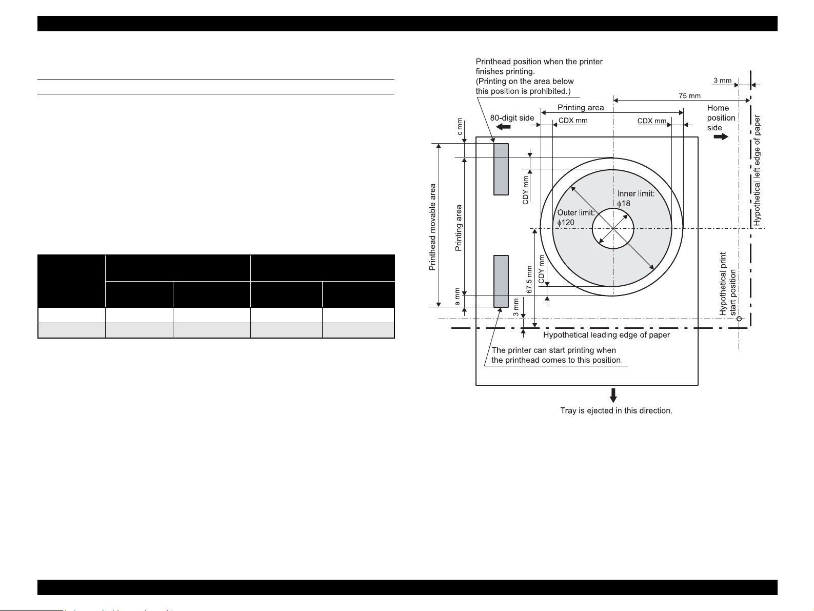
1.2.1.1 Printing Area (CD-R)
Printing Area
Figure 1-10 shows the printing area for CD-R. Outer and inner limit of printing area is
φ120 and φ18, respectively. The process of determining the reference point and
defining the printing area is described below.
(1) The reference point in main-scanning direction is 72 mm off from the center
of the CD-R (toward the home position side). The center of the CD-R is
detected automatically.
(2) The reference point in paper-feed direction is 67.5 mm off from the center of
the CD-R (toward the downstream side).
(3) User can change the center position of the CD-R in the range of ± CDX mm
(main-scanning direction) and ± CDY mm (paper-feed direction).
Figure 1-10. Printing Area (CD-R)
Unit
Amount of the Nozzles Off the
Paper Edges
Adjustable Range of the CD-R
Center Position
a (Top) c (Bottom)
CDX
(X direction)
CDY
(Y direction)
inch 358/360 359/360 ±14/180 ±28/360
mm 25.26 25.33 ±2 ±2

EPSON Stylus Photo 1400/1410 Revision A
PRODUCT DESCRIPTION PG Setting 16
1.3 PG Setting
EPSON Stylus Photo 1400/1410 features an Auto Platen Gap (APG) adjuster that sets the platen gap to suit the type of paper being used, and this prevents paper misalignment and
jamming that can cause problems during operation.
Table 1-4 shows the relationship among PG positions, media, and sensors.
Note *: APG sensor 1 outputs L between each PG position.
Table 1-4. PG Setting
PG Position
PG (– –) PG (–) PG (Typ) PG (+) PG (++) Release
Printing
• Some special paper • Special paper
• Plain paper
•PG (−) rubbing
prevention
• Envelope
• PG (Typ) rubbing
prevention
•CD-R
---
Not printing
--- ---
• Standing-by after
power-on
(Output tray is lowered)
• At power-off
---
• Initialization at power-
on
• Cleaning (wiping)
• Replacing ink
cartridge(s)
• Waiting for CD-R to be
fed
• Removing jammed
paper
PG value 1.05 mm (0.041 inch) 1.2 mm (0.047 inch) 1.7 mm (0.06 inch) 2.1 mm (0.08 inch) 4.5 mm (0.17 inch) ---
Sensor PG (– –) PG (–) PG (Typ) PG (+) PG (++) Release
APG sensor 1
*
HHHHHH
APG sensor 2 L L L L H H
EPSON Stylus Photo 1400/1410 Revision A
PRODUCT DESCRIPTION Printer Function 17
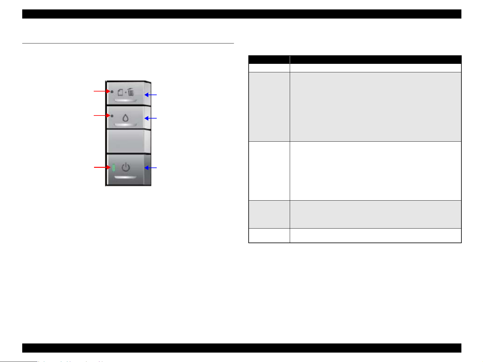
1.4 Printer Function
1.4.1 Operator Controls
The control panel is shown in the figure below.
Figure 1-11. Operator Controls
1.4.2 Buttons
Power button
Paper button
Ink button
1.4.3 LED Indicators
Power LED: Green
Paper LED: Red
Ink LED: Red
1.4.4 Panel Functions
Note *: CD-R guide error occurs when the CD-R guide is opened during printing, or when
the printer receives a print job for cut-sheet with the CD-R guide opened.
Ink button
Paper button
Power button
Ink LED (red)
Paper LED (red)
Power LED (green)
Table 1-5. Normal Panel Functions
Button Function
Power
• Turns on/off the power.
Paper
• Loads or ejects the paper (Invalid when the CD-R guide is opened.)
• Clears double feed error and resumes printing.
• Cancels the current print job during printing.
• Clears paper out error and resumes printing.
• Clears paper jam error, ejects the paper, and resumes printing.
• When ink end (any cartridge) error occurs, the ink cartridge holder moves
to the ink replacement position.
• The ink cartridge holder returns to the home position from the ink
replacement position.
Ink
• The ink cartridge holder moves to the ink replacement position.
• When ink low, ink end, or no ink cartridge error occurs, the ink cartridge
holder moves to the ink check position.
• When the ink cartridge holder is in the ink check position, the holder
moves to check another cartridge of different color, or the holder moves to
the ink replacement position.
• The ink cartridge holder returns to the home position from the ink
replacement position.
Ink
(When pushed
and held for 3
seconds)
• Starts printhead cleaning
• When ink low, ink end, or no ink cartridge error occurs, ink replacement
sequence starts.
CD-R guide
(When opened)
• Clears CD-R guide error.
*
EPSON Stylus Photo 1400/1410 Revision A
PRODUCT DESCRIPTION Printer Function 18
Power-on functions
Power-off function
Note : Press the power button first. Making sure the power button is not pressed down, push
and hold the ink button for 7 seconds.
CD-R printing
1.4.5 Printer Condition and Panel LED Status
Note *: All the LEDs turn on for 0.2 seconds.
Note : ---: No change to LED.
Blink: 0.5 seconds on, 0.5 seconds off (repeat)
Blink2: 0.2 seconds on, 0.2 seconds off, 0.2 seconds on, 0.4 seconds off (repeat)
Blink3: 0.2 seconds off, 0.2 seconds on, 0.2 seconds off, 0.4 seconds on (repeat)
Blink4: 0.8 seconds on, 0.2 seconds off
Hi-speed Blink: 0.1 seconds on, 0.1 seconds off (repeat)
Alt Blink: Continuous alternating blink of Paper and Ink LEDs.
Table 1-6. Panel Function during Power-on
Button Held during Power-on Function
Paper
Starts status printings.
Ink
Starts in rubbing reduction mode.
Table 1-7. Panel Function during Power-off
Button Held during Power-off Function
Ink Forced power-off.
Table 1-8. Panel Function during Printing on CD-R
Button CD/DVD Tray Function
Paper
Inserted
• Clears CD/DVD tray error.
• Cancels the current print job during
printing.
Not inserted Clears CD/DVD tray error
Ink
Inserted Same as normal panel functions (including
the functions when the button is pushed and
held for 3 seconds).
Not inserted
Table 1-9. Panel Status
Printer Status
Button LEDs
Priority
Power Paper Ink
Power ON (Ready) condition On --- --- 12
Camera being connected
(No rubbing reduction)
Blink2 --- --- 12
Camera being connected
(Rubbing reduction)
Blink4 --- --- 12
Ink low --- --- Blink 11
Unsupported device
connection error
--- Blink2 Blink3 10
Data processing Blink --- --- 10
Loading/Ejecting paper Blink --- --- 10
No ink cartridge or Ink end --- --- On 9
CSIC error --- --- On 9
Processing ink sequence Blink --- --- 8
Ink cartridge change mode Blink --- --- 7
CD/DVD tray error --- On --- 6
Paper out --- On --- 6
Double feed --- On --- 6
Paper (CD-R) jam --- Blink --- 5
CD-R guide error
--- Blink2 Hi-speed Blink 4
Maintenance request Off Alt Blink Alt Blink 3
Fatal error Off Hi-speed Blink Hi-speed Blink 2
Powering OFF Hi-speed Blink Off Off 1
Reset request
*
On On On ---

EPSON Stylus Photo 1400/1410 Revision A
PRODUCT DESCRIPTION Printer Function 19
1.4.6 Errors
Table 1-10. Errors
Error Status Occurrence Condition Remedy
Ink end
The printer has almost run out of
ink in any cartridge.
Carry out the ink cartridge
replacement operation. Remove the
CD/DVD tray before pressing the Ink
button.
Paper out
The printer fails to load a sheet of
paper.
Load a paper in the ASF, and press
the Paper button to feed the paper. Set
the CD-R guide lever to the ASF
position before pressing the button.
Paper jam
1. The printer cannot eject the
remaining paper at power-on
within predetermined steps.
2. The printer cannot eject the
paper by FF command or
pressing the Paper button.
3. The printer cannot eject the CD/
DVD tray.
4. The printer prints on a 58 mm
(2.3 inch) or shorter length of
paper.
1. ASF mode
Remove the jammed paper and
press the Paper button. Set the CD-
R guide lever to the ASF position
before pressing the button.
2. CD-R mode
Remove the jammed CD/DVD tray
and press the Paper button.
Double feed error
The printer detects that two sheets
have stuck together during paper
feed.
Press the Paper button to eject the
paper. Set the CD-R guide lever to the
ASF position before pressing the
button.
No ink cartridge
Ink cartridge error
1. The printer detects at least one
ink cartridge is missing.
2. The printer cannot communicate
with the CSIC chip on one of the
cartridges.
Make sure genuine EPSON ink
cartridges are inserted and press the
Ink button. Remove the CD/DVD tray
before pressing the button.
Maintenance
request
When the total quantity of wasted
ink used for cleaning and flushing
reaches the calculated limit.
Replace the waste ink pad and reset
the Waste Ink Counter.
Fatal error
The printer cannot control error.
Turn the power off and on again.
CD-R guide error
1. The printer receives a print job
for cut-sheet when the CD-R
guide lever is set to the CD-R
position.
2. The CD-R guide lever is set to
the CD-R position during ASF
printing.
Set the CD-R guide lever to the ASF
position.
1. The printer receives a print job
for CD-R media when the CD-R
guide lever is set to the ASF
position.
Set the CD-R guide lever to the CD-R
position.
CD/DVD tray
error
CD/DVD tray is not inserted. Insert a CD/DVD tray and press the
Paper button.
Unsupported
device
connection error
Unsupported device is connected. Disconnect the device from the USB
connector.
Table 1-10. Errors
Error Status Occurrence Condition Remedy
EPSON Stylus Photo 1400/1410 Revision A
PRODUCT DESCRIPTION Size and Weight 20
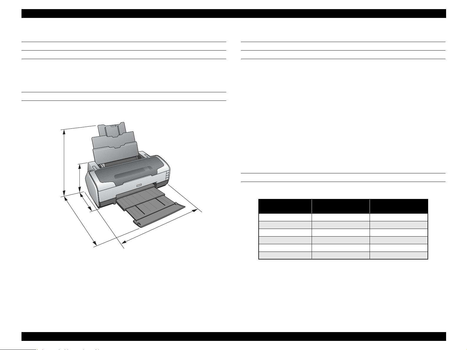
1.5 Size and Weight
Dimensions
Storage: 615 mm (24.2 in.) W x 314 mm (12.4 in.) D x 223 mm (8.8 in.) H
Printing: 615mm (24.2 in.) W x 803 mm (31.6 in.) D x 413 mm (16.3 in.) H
Weight
11.5 Kg (25.4 lbs.)
Figure 1-12. Physical Dimensions, in mm
1.6 Accessories
Standard accessories
User’s guide
Ink cartridge (one for each of the six colors)
Software CD-ROM
Setup sheet
On-line questionnaire sheet
Customer Satisfaction Card (information card)
Guarantee card
CD/DVD print kit
CD/DVD tray
Small CD insert
Consumable and optional supplies
Ink cartridge
Network Print Server
615
314
803
223
413
Color EAI/EUR
Latin / CIS / EAL
Middle East / Africa
Black T0791 T0811
Cyan T0792 T0812
Magenta T0793 T0813
Yellow T0794 T0814
Light Cyan T0795 T0815
Light Magenta T0796 T0816

CHAPTER
2
OPERATING PRINCIPLES

EPSON Stylus Photo 1400/1410 Revision A
OPERATING PRINCIPLES Overview 22
2.1 Overview
This chapter explains the operating principles of the mechanical sections and electrical
circuits in this product. The main components of this product are as follows.
Control Circuit Board : C655 MAIN
Power Supply Circuit Board : C589 PSB
Control Panel Board : C589 PNL
Head Circuit Board : C653 HEAD
2.2 Printer Mechanism
In common with previous model, this printer uses DC motors and stepping motors as
power source. The following table describes the motor types and their applications.
The basic mechanism is the same as the Stylus Photo R1800.
Figure 2-1. Printer Mechanism Outline
Table 2-1. Motors
Motor Name Type Applications/Functions
CR Motor DC motor with brushes
Drives the Carriage. Makes very little driving
noise. Controlled by the CR linear scale and CR
encoder sensor.
PF Motor DC motor with brushes
Drives the paper feed roller for the fixed-value
paper loading or the paper feed/eject operation. To
grasp the paper feed pitch, the precision gear
surface is fitted with the PF Scale and the PF
Encoder Sensor is used to control the motor.
APG Motor DC motor with brushes
Drives the Carriage Unit at the time of PG setting.
The two APG Sensors and Carriage Shaft are
driven vertically to control the motor.
ASF Motor
4-phase, 48-pole PM type
stepping motor
Drives the paper feed operation of the ASF. Since
this is a stepping motor, no scales or photo sensors
are required to grasp the driving conditions.
Pump Motor
4-phase, 48-pole PM type
stepping motor
Drives the pump, wiper, etc. of the Ink System.
Since this is a stepping motor, no scales or photo
sensors are required to grasp the driving
conditions.
Rear Paper
Eject Roller
Front Paper
Eject Roller
PW Sensor
CR Scale
PF Roller
PF Encoder
Sensor
PF Scale
PF Motor
Carriage
Unit
Ink System
Unit
Pump Motor
CD-R Sensor
Carriage
Shaft
APG Sensors
APG Motor
APF Sensor
Timing Belt
CR Encoder
Sensor
LD Roller
Retard
Roller
PE Sensor
ASF Motor
CR Motor

EPSON Stylus Photo 1400/1410 Revision A
OPERATING PRINCIPLES Printer Mechanism 23
2.2.1 Carriage Mechanism
The Carriage mechanism consists of parts/units such as the Carriage Motor (CR
Motor), Carriage Shafts, Platen Gap Adjustment Mechanism and Carriage Lock
Mechanism.
2.2.1.1 Carriage Mechanism
The following indicates the specifications of the CR motor (DC motor) that drives the
Carriage.
Closed loop control based on the CR Motor (DC Motor) and CR Encoder Sensor has
advantages in stabilized print quality and silent operation.
Heat Generation Control
The printer has a mechanism to reduce the variations in the torque constant and
coil resistance of the DC motors, and variations in output voltage of the Power
Supply Board to obtain a designated heating value.
CR Variation Measurement Sequence
The variations mentioned above are measured in a CR variation measurement
sequence when the CR mechanical load is in the initial status and saved into the
EEPROM. According to the saved information, the printer controls the drive
voltage to obtain a designated driving current. This minimizes the unit-to-unit
variation.
CR Measurement Sequence
To set the appropriate drive current value according to the CR mechanical load,
the mechanical load is measured in a CR measurement sequence and saved into
the EEPROM at power-on or after replacing the Ink Cartridge(s).
The above control and sequences correct the drive current value of the CR Motor
according to not only the mechanical load but also the variations of the motors. In
addition, the resultant CR drive current value is used to calculate a heating value, and
when the specified heating value is reached, wait time is provided per CR path for
printing.
Table 2-2. CR Motor Specifications
Item Specifications
Type DC motor with brushes
Drive voltage +42V ± 5% (voltage applied to driver)
Armature resistance 23.6Ω ± 10%
Inductance 17.5mH ± 25%
Drive method PWM, constant-current chopping
Drive IC A6628

EPSON Stylus Photo 1400/1410 Revision A
OPERATING PRINCIPLES Printer Mechanism 24
2.2.1.2 Carriage Home Position Detection
As in the previous model, the Carriage Home Position is detected using the drive
current of the CR Motor and the speed/position signal of the CR Linear Encoder.
The basic home position detection sequence is described below.
1. The CR linear encoder pulse counter in the CPU is reset by the initialization
operation performed at power-on.
2. When the CR Motor rotates counterclockwise, the Carriage Unit moves from left
to right. When the following conditions are satisfied, the CPU assumes that the
Carriage Unit made contact with the right frame.
The ASIC detects 935/1500 counts or more in the PWM output under CR
Motor load positioning control.
P1 (number of output pulses from when the power is switched on till the
Carriage Unit makes contact with the right frame) is 19 steps or less.
3. When the CR Motor rotates clockwise, the Carriage Unit moves from right to left.
When the following conditions are satisfied, the CPU assumes that the Carriage
Unit reached the CR lock confirmation position.
The ASIC detects 600/1500 counts or more in the PWM output under CR
Motor load positioning control.
A difference between P1 and P2 (number of output pulses from when the
Carriage Unit made contact with the right frame until it reaches the Carriage
lock confirmation position) is 19 steps or less.
4. When the CR Motor rotates counterclockwise to move the Carriage from left to
right and the CPU detects 935/1500 counts or more in the PWM output under CR
Motor load positioning control, the printer judges that the Carriage has moved to
the far right position (in contact with the right frame).
5. When a difference between P1 and P3 (number of output pulses from when the
Carriage Unit reached the Carriage lock confirmation position until it makes
contact with the right frame) is 4 steps or less, the printer judges that the Carriage
Unit is in the home position.
IC9 (CPU-ASIC) sets the drive current value adequate for the Carriage Unit motion
and outputs it to the motor driver.
Based on the signal output from IC9 (CPU-ASIC), IC11 (Motor Driver) outputs the CR
Motor drive current to the CR Motor.
2.2.1.3 Sequence Used for PW Detection
The PW (paper width) Sensor installed on the bottom of the Carriage Unit is used to
control the printer according to various sequences.
The following briefly describes the operating principle of the PW Sensor.
A dark voltage is measured by the PW Sensor in three places at the right flat area (area
without the absorber) on the Front Paper Guide every time the printer is turned on, and
the measurement values are saved into the EEPROM as threshold values.
Threshold value detection voltage: Paper present
Threshold value detection voltage: Paper absent
The following sequences are performed.
Detection of Left and Right Edges of Paper Control
Before Printing
The printer sets the print range according to the paper-size information from
the Driver and the actual paper-size detected by the PW sensor.
During Printing
When executing a borderless printing, the printer sets the off-range margins
by detecting the paper edges with the PW Sensor. When the resolution is 1440
x 1440 (VSD3) or 2880 x 1440 (VSD3) dpi, the printer performs the Off-
Range Thinning Out Control to make a further correction to the off-range
margins.
Detection of Top Edge of Paper Control
Before starting a print job, the printer detects the top edge of a loaded single sheet
of paper to set the off-range top margin. (Only when not detecting the top edge of
paper with the PW Sensor.)
Detection of Bottom Edge of Paper Control
After starting a borderless printing, the printer sets the off-range bottom margin.
Detection of Edges of CD-R Control
Before starting to print, the PW Sensor detects top, bottom, left and right edges of
the CD-R. See Section 2.2.3.3 CD-R Printing Mechanism on page 29.
EPSON Stylus Photo 1400/1410 Revision A
OPERATING PRINCIPLES Printer Mechanism 25
Detection of CD/DVD Tray Control
Before starting to print, determines the type of media.
PW sensor dark voltage (VH) measurement
PW sensor dark voltage (VH) measurement is performed at the following timings
and locations and used to calculate the threshold value of whether paper is present
or not.
CD/DVD Tray
When printing on a CD-R, the dark voltage is measured on the CD/DVD tray,
and the threshold value (VS) is then calculated and saved in the EEPROM
area as a PW detection level.
• Threshold value detection voltage: CD-R present
(tray home position detected)
The measurement voltage in the presence of the CD-R is saved into the
EEPROM as a white level. The white level value is used to check the sensor
deterioration condition on occasions such as servicing.
• If the measurement value of the white level is close to that of the PW
detection level, it means that the sensor is dirty or deteriorated.
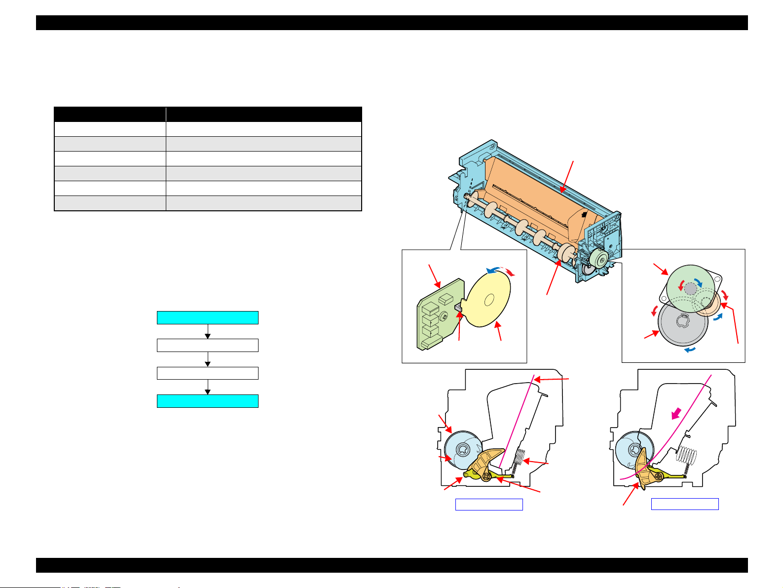
2.2.1.4 APG (Auto Platen Gap) Adjustment Mechanism
The following indicates the specification of the DC motor that drives the APG adjuster.
The APG Motor (DC Motor) and two APG Sensors drive the PG Cam to automatically
adjust the PG amount according to the paper.
Figure 2-2. APG Mechanism
Table 2-3. APG Motor Specifications
Item Specifications
Type DC motor with brushes
Drive voltage +42V ± 5% (voltage applied to driver)
Armature resistance 64.7Ω ± 15%
Inductance 37.6mH ± 25%
Rotor Inertia 3.94gcm
2
Drive method PWM, constant-current chopping
Drive IC A6628
Carriage Shaft
Carriage Unit
APG Motor
PG CamAPG Sensor
APG
Sensor
EPSON Stylus Photo 1400/1410 Revision A
OPERATING PRINCIPLES Printer Mechanism 26
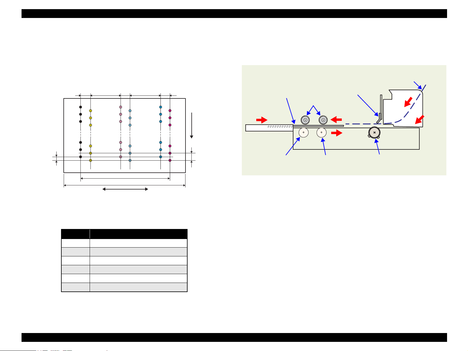
2.2.2 Printhead Specifications
The Printhead of this product is a F3-Mach head.
The following shows the arrangement of the nozzles and the color arrangement of each
nozzle line when viewing the Printhead from behind.
Figure 2-3. Nozzle Arrangement
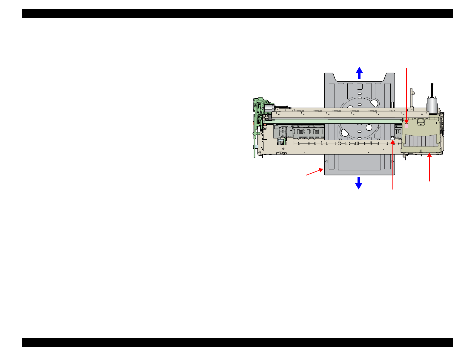
2.2.3 Paper Feeding Mechanism
The paper feeding mechanism is a mechanism that feeds paper or CD/DVD tray to the
PF Roller Shaft.
Figure 2-4. Paper Feeding Mechanism
Table 2-4. Nozzle Lines and the Corresponding Ink Color
Line Ink
ABlack
B Yellow
C Light-Magenta
D Light-Cyan
ECyan
F Magenta
14.95mm
22.81mm
Carriage moving direction
Paper feeding
direction
0.141mm
(1/180inch)
0.282mm
(1/90inch)
Line A
Line B
6.209mm
(176/720inch)
0.846mm
(24/720inch)
0.846mm
(24/720inch)
6.209mm
(216/720inch)
Line C
Line D
Line E
Line F
0.846mm
(24/720inch)
CD/DVD Tray
Front Paper Eject Roller
Rear Paper Eject Roller
PF Roller
Star Wheel Rollers
PE Sensor
Cut sheet
EPSON Stylus Photo 1400/1410 Revision A
OPERATING PRINCIPLES Printer Mechanism 27
2.2.3.1 ASF Paper Feeding Mechanism
The following shows the specifications of the stepping motor that drives the ASF Assy.
Driven by the ASF Motor, the ASF Assy performs the following feeding operation.
1. When a paper feeding command is issued from the PC or the Paper button of the
panel is pressed after power-on, the driving force of the ASF Motor begins to be
transmitted to the LD Roller following the route shown below.
2. When the LD Roller starts rotating, the flag of the ASF Sensor Wheel comes free
from the notch on the ASF Sensor. At the same time, the Paper Back Lever
becomes free from the Cams located at the left and right ends of the LD Roller,
then the Paper Holder on the Paper Back Lever inclines downward by tensile force
of the Paper Back Lever Torsion Spring.
3. By the LD Roller's rotation, the Hopper is released from the Hopper Cams located
on the left and right ends of the LD Roller, and the Hopper pops up by tensile force
of the Hopper Compression Spring.
4. When the next sheet of paper is fed by the LD Roller and the Retard Roller, the
Hopper is pressed against the Frame again by the Hopper Cams, and the Paper
Holder of the Paper Back Lever rises by the Cams on the left and right ends of the
LD Roller to prevent the next sheet from being fed with the previous sheet.
5. The LD Roller stops to rotate when it makes one revolution and the flag of the
ASF Sensor Wheel returns to the ASF Sensor.
Figure 2-5. ASF Paper Feeding Mechanism
Table 2-5. ASF Motor Specifications
Item Specifications
Type
4-phase, 48-pole PM type stepping motor
Drive voltage
+42V ± 5% (voltage applied to driver)
Winding resistance
7.0Ω ± 10% (per phase at 25°C)
Inductance
10.2mH ± 20% (1kH, 1Vrms, at 25°C)
Drive method
Bipolar drive/constant-current drive
Drive IC
A6628
ASF Motor
Combination Gear 29, 11
LD Shaft Spur Gear
LD Roller
ASF Motor
ASF
Sensor
Combination
Gear 29.11
LD Shaft
Spur Gear
Relay Board
ASF Sensor
Wheel
Standby State
Feeding Paper
LD Roller
Hopper
Hopper
Compression
Spring
Retard
Roller
Paper
Paper Back Lever
LD
Roller
Cam
Paper Back Lever
Torsion Spring

EPSON Stylus Photo 1400/1410 Revision A
OPERATING PRINCIPLES Printer Mechanism 28
2.2.3.2 CD/DVD Tray Base Lock Mechanism
To prevent the Printhead from being damaged by mistake, the printer is designed to
lock the CD/DVD Tray Base when the Carriage Unit is out of its home position.
The following explains the lock mechanism of the CD/DVD Tray Base.
Lock Release Sequence
1. When the Carriage Unit returns to its home position, the Pump Motor drive is
transmitted to the Paper EJ Lock Release Cam.
2. The salient of the Cam presses down the Paper EJ Transmission Lock Lever
to release the tab of the Paper EJ Lock Lever from the Paper EJ Transmission
Lock Lever.
3. The CD-R Release Lever comes free from the Paper EJ Lock Lever and
comes down to enable the CD/DVD Tray Base to open.
When the Carriage Unit is out of its home position, the salient of the Paper EJ Lock
Release Cam does not press down the Paper EJ Transmission Lock Lever, and the tab
of the Paper EJ Lock Lever is not released. Therefore, the CD/DVD Tray Base cannot
be opened.
Figure 2-6. CD/DVD Tray Base Lock Mechanism
CD/DVD Tray Base
Paper EJ Lock
Release Cam
Salient
Paper EJ
Transmission
Lock Lever
Paper EJ Lock
Lever
Jointed PositionTab
CD-R Release Lever
EPSON Stylus Photo 1400/1410 Revision A
OPERATING PRINCIPLES Printer Mechanism 29
2.2.3.3 CD-R Printing Mechanism
CD/DVD Tray Home Position Detection Sequence
The following sequence is performed after opening the Front Cover (CD-R
Sensor: closed), inserting the CD/DVD Tray to the specified position, and pressing
the Paper button.
When the close signal of the CD-R Sensor is detected, no paper is fed from the
ASF even if the Paper button is pressed. In this case, pressing the Paper button
executes a CD/DVD Tray home position detection sequence.
1. When the APG Assy is driven, the PG position is set to “++” and the Driven
Roller of the Upper Paper Guide presses onto the CD/DVD Tray.
2. When the Carriage Unit moves to the left and the PW Sensor detects the CD-
R, the Carriage Unit returns to its home position (HP).
3. After waiting for about 5 seconds at the HP, the Carriage Unit moves to the
CD/DVD Tray HP detectable position (right end of the CD/DVD Tray).
4. The CD/DVD Tray is pulled towards the ASF, the PW Sensor detects the CD/
DVD Tray HP, and then the Carriage Unit moves to the center of the CD/
DVD Tray.
5. When the PW Sensor detects the white marking in the center of the CD/DVD
Tray, the CD/DVD Tray is fed in the paper ejection direction.
6. The Carriage Unit moves to the left, the PW Sensor detects the white marking
on the left, then the Carriage Unit moves to the right, and the PW Sensor
detects the white marking on the right.
7. The Carriage Unit moves to the center of the CD/DVD Tray, and the PW
Sensor starts detection of the front and back direction of the CD-R. After the
front end of the CD-R is detected, the CD/DVD Tray is fed towards the paper
ejection direction, and the back end of the CD-R is detected. After that, the
CD/DVD Tray is fed to the center of the CD-R in the paper ejection direction.
8. The Carriage Unit moves to the left, and the PW Sensor starts detection in the
horizontal direction of the CD-R. After the left end of the CD-R is detected,
the Carriage Unit moves to the right, and the right end of the CD-R is
detected.
9. The Carriage Unit stops after moving to the CD/DVD Tray HP detectable
position, then the CD/DVD Tray is fed towards the ASF.
10. When the CD/DVD Tray stops operating, the Carriage Unit moves to the
carriage HP and stands by.
If the CD/DVD Tray HP, the white marking, or the CD-R cannot be detected within the
steps predetermined for the CD/DVD Tray HP detection sequence, the CD/DVD Tray
is ejected and Paper Out Error is displayed.
Figure 2-7. CD-R Printing Mechanism
Carriage Unit
PW Sensor
CD-R Home Position
CD/DVD Tray
EPSON Stylus Photo 1400/1410 Revision A
OPERATING PRINCIPLES Printer Mechanism 30
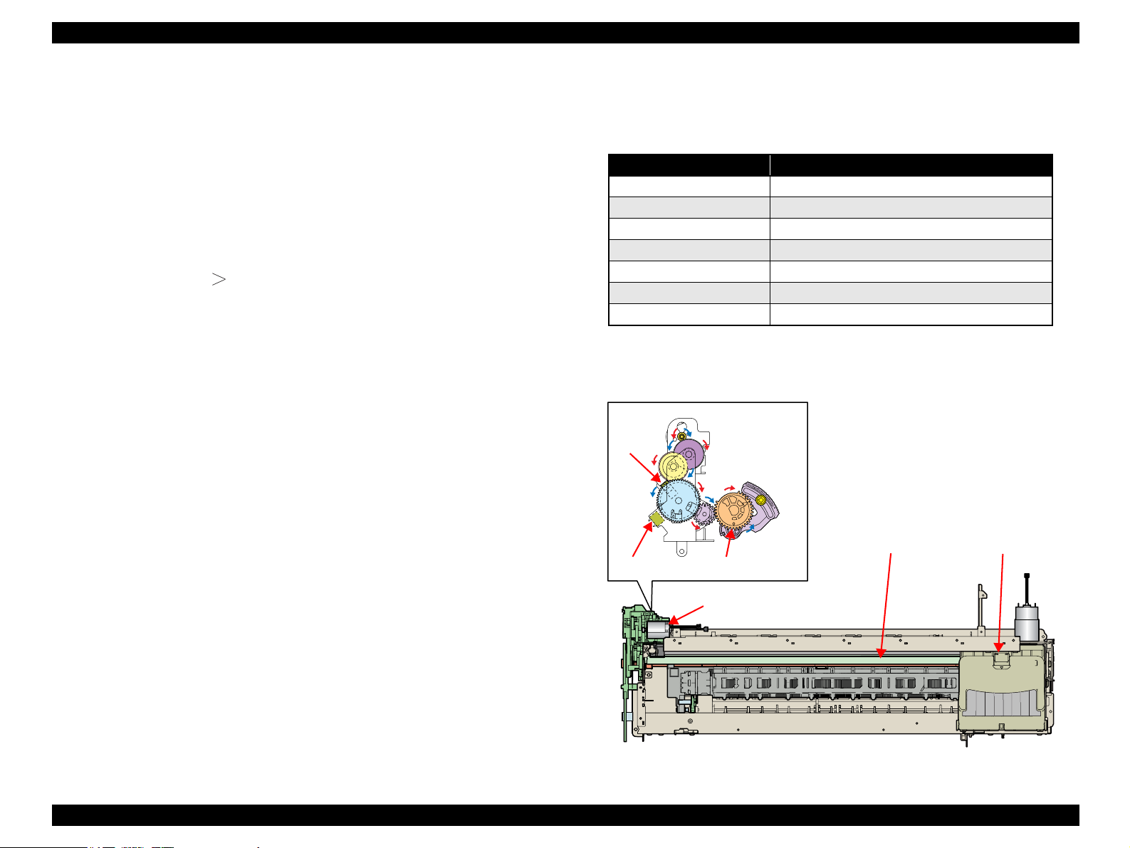
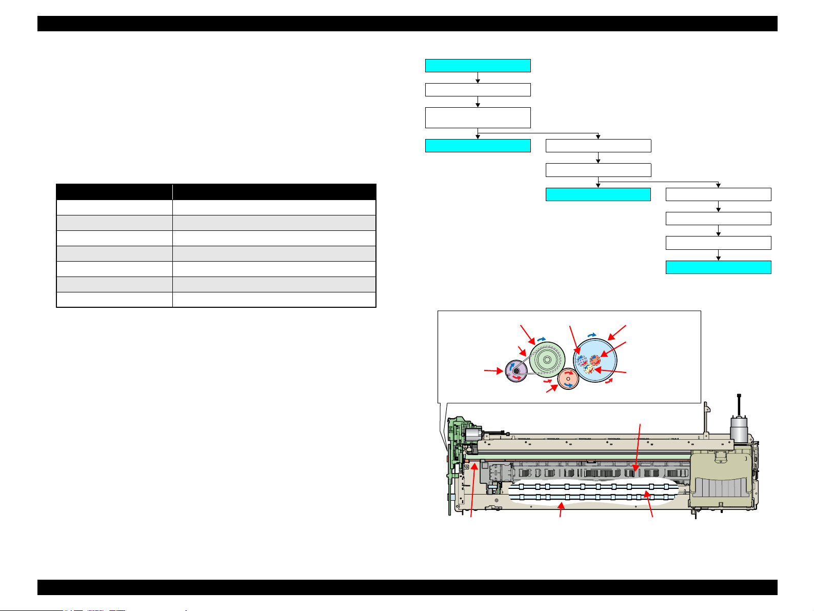
2.2.4 Paper Feeding Mechanism
The Paper Feeding Mechanism is designed to transfer the paper fed from the ASF, or
the CD-R fed from the CD/DVD Tray according to the print data.
2.2.4.1 Paper Feeding Mechanism
The following shows the specifications of the DC motor that drives the Paper Feeding
Mechanism.
Like the CR Motor, a DC motor is used as the PF Motor in this product.
Closed loop control based on the DC Motor and Rotary Encoder has the following
advantages.
Improved paper feed accuracy
Paper feed amount control
The PF Motor drive is transmitted to the PF Roller and the Paper EJ Roller following
the route shown below.
The following shows the part names and outline of the drive transmission path.
Figure 2-8. Paper Feeding Mechanism
Table 2-6. PF Motor Specifications
Item Specifications
Type DC motor with brushes
Drive voltage +42V ± 5% (voltage applied to driver)
Armature resistance 21.2Ω ± 10%
Inductance 17.2mH (1kHz)
Rotor Inertia 18.8gcm2
Drive method PWM
Drive IC A6628
PF Motor
PF Timing Belt
PF Roller
Spur Gear 31.5
Spur Gear 68
Front Paper Eject Roller
Spur Gear 16; B (front)
Spur Gear 15.5
Rear Paper Eject Roller
Combination Gear
36.294, 55
Spur Gear 16; B (rear)
Front Paper Guide
PF Roller
PF Motor
Front Paper Eject Roller
Rear Paper Eject Roller
PF Timing Belt
Combination Gear
36.294, 55
Spur Gear 31.5
Spur Gear 16;
B (front)
Spur Gear 68
Spur Gear 15.5
Spur Gear 16; B (rear)
EPSON Stylus Photo 1400/1410 Revision A
OPERATING PRINCIPLES Printer Mechanism 31
The fed paper is detected by the PE Sensor, and its front end is then transferred to the
front of the Front Paper Guide.
To eliminate the deflection of the paper, the paper is then returned toward the ASF
Assy by the specified number of steps according to the paper feeding mode.
The paper is re-transferred to the specified paper locating position of the Front Paper
Guide.
2.2.4.2 PF Measurement Sequence
The mechanical load in the paper feeding path is measured in the following cases
to perform control so that an adequate current value is set according to the
mechanical load.
When power is switched on
When the Ink Cartridge is replaced
When the mechanical load in the paper feeding path reaches the specified value,
Fatal Error is displayed.
2.2.5 Ink System Mechanism
The Ink System Mechanism consists of the following units.
Pump Unit (including the CR Lock Lever)
Cap Unit
2.2.5.1 Pump Unit
The Pump Unit is designed to suck ink from the Printhead or Cap Unit. The Cap Unit
has a built-in Head Cleaning Wiper.
The following shows the specifications of the stepping motor that drives the Pump
Unit.
The following operations are performed when the drive of the Pump Motor is
transmitted to the Pump Unit.
Note * : The direction (CW or CCW) was determined by viewing the motor from the output
shaft of the motor mounting plate.
Table 2-7. Pump Motor Specifications
Item Specifications
Type 4-phase, 48-pole PM type stepping motor
Drive voltage +42V ± 5% (voltage applied to driver)
Winding resistance 10.3Ω ± 10% (per phase at 25°C)
Inductance 13.4mH ± 20% (1kH,1Vrms)
Drive method Bipolar drive/constant-current drive
Drive IC A6628
Table 2-8. Pump Motor Rotation Directions and Functions
Pump Motor Rotation Direction* Functions
CW direction
• Cap closing
• Ink suction
• Wiper resetting
• CR Lock setting
CCW direction
• Cap opening
• Pump release
• Wiper setting
• CR Lock resetting
Loading...