


 Loading...
Epson DM-M820-013, DM-M820-023, DM-M820-113, DM-M820-123, DM-M820-014 Technical Reference Manual
...Technical Reference
Manual
MR Series
English
EPSON
403308709 Rev. I

|
|
|
|
|
MR Series Technical Reference Manual |
|
|
|
|
|
|
Revision Table |
|
|
|||
|
|
|
|
|
|
|
|
Rev. |
Page |
|
Description |
|
|
|
|
|
|
|
|
Rev. A |
All pages |
|
Newly authorized |
|
|
|
|
|
|
|
|
Rev. B |
Chapter 5 |
|
BIOS updated from 2.06 to 2.08 |
|
|
|
|
|
|
|
|
|
9-2 |
|
Added explanation and listing of "touch panel position adjust jig" in "Required Tools". |
|
|
|
|
|
Reason for change: The tool is now supplied for assembling the touch panel assembly. |
|
|
|
|
|
|
|
|
|
9-18—20 |
|
Added new explanation for installation of the touch panel assembly.Reason for |
|
|
|
|
|
change: |
|
|
|
|
|
The touch panel assembly needs to be assembled and attached to the main frame |
|
|
|
|
|
using the “touch panel position adjust jig“tool. |
|
|
|
|
|
|
|
|
|
9-21 |
|
Added the explanation below in the “removing the LCD“. |
|
|
|
|
|
Note: |
|
|
|
|
|
When replacing the LCD, you need to change the electric-conductive tape also. |
|
|
|
|
|
Reason for change: This explanation was missing. |
|
|
|
|
|
|
|
|
|
B-7,9,11,13 |
|
Added the parts in the Parts List and Exploded Diagram. |
|
|
|
|
|
For DM-M820-014: |
|
|
|
|
|
- upper plate (Ref# 120) |
|
|
|
|
|
- lower plate (Ref# 121) |
|
|
|
|
|
- touch panel assembly (Ref#:1056) |
|
|
|
|
|
Reason for change; |
|
|
|
|
|
The for the touch panel assembly unit was changed. |
|
|
|
|
|
For IM-800: |
|
|
|
|
|
- Ferrite core (Ref#; 220) |
|
|
|
|
|
Reason for change: This explanation was missing. |
|
|
|
|
|
|
|
|
Rev. C |
1-7,9.2-2,4 |
|
Add the Indiividual Sales of IM and DM. |
|
|
|
|
|
|
|
|
|
vii,viii,1-1,6,10,2- |
Add the AC Adapter OI-MR01. |
|
|
|
|
4,7-4 |
|
|
|
|
|
|
|
|
|
|
|
1-3-6,11,2-1,6- |
|
Revision of the illustration. |
|
|
|
1,2 |
|
|
|
|
|
|
|
|
|
|
|
3-1,3 |
|
Revision of the Hardware diagram. |
|
|
|
|
|
|
|
|
|
4-1,3,17,19 |
|
Add the installation for Windows XP Professional Locally Procured Edition. |
|
|
|
|
|
|
|
|
|
4-2 |
|
Add the explanation for Driver CD-ROM. |
|
|
|
|
|
|
|
|
|
4-3 |
|
Add the Touch Panel Driver for Asian. |
|
|
|
|
|
|
|
|
|
4-26-27, |
|
Add the uninstaiiing the Serial Port Driver for Windows 2000. |
|
|
|
|
|
|
|
|
|
4-32 |
|
Add the Installing the Service Pack 6a for Windows NT. |
|
|
|
|
|
|
|
|
|
5-7 |
|
BIOS updated from 2.06 to 2.09. |
|
|
|
|
|
|
|
|
|
5-16-19 |
|
Add the supplementary explanation for Power Management. |
|
|
|
|
|
|
|
|
|
Chapter 8 |
|
Chanded the explanations for troubleshooting. |
|
|
|
|
|
The changed points; |
|
|
|
|
|
The each explanation for the trouble related to specific models is noted by an icon. |
|
|
|
|
|
Reason for change; |
|
|
|
|
|
The display with the touch panel assembly and without the MSR unit is newly supplied. |
|
|
|
|
|
|
|
|
|
9-3 |
|
Addd the explanation for the DM-M820-015 in the work diagram for DM-M820. |
|
|
|
|
|
Reason for change; |
|
|
|
|
|
The display (DM-M820) with the touch panel assembly and without the MSR unit is |
|
|
|
|
|
newly supplied. |
|
|
|
|
|
|
Rev. I |
i |

Rev. |
Page |
Description |
|
|
|
|
9-24,27,28,37 |
Added the explanation for disassembly and assemblyof the parts below. |
|
|
-PCI card |
|
|
-Switch cable assembly |
|
|
|
|
9-29 |
The method of disassembly and assembly the CD/FDD bracket is changed. |
|
|
The changed point. |
|
|
One screw and stopper is added to fix the CD/FDD bracket correctly. |
|
|
Reason for change; |
|
|
The part is changed to prevent the CD/FDD bracket from connection failure. |
|
|
|
|
B-11—15 |
Added parts list and block diagram for the model DM-M820-015. |
|
|
Reason for change; |
|
|
The display with the touch panel assembly and without the MSR unit is newly supplied. |
|
|
|
Rev.D |
9-19 |
Added the explanation of attaching the touch panel. |
|
|
Reason for change; |
|
|
To be supplied the touch panel unit (115) newly. |
|
|
|
|
9-30 |
Changed the explanation of attaching the CD-ROM unit with the screws “C.B.screw. |
|
Appendix B |
2x2.5.F/ZN”. |
|
|
Reason for change; |
|
|
T wo screws “C.B.screw. 2x2.5.F/ZN“ attaching the CD-ROM unit are added. |
|
|
|
|
9-32 |
Deleted the explanation of attaching the gasket to the FDD unit. |
|
Appendix B |
Reason for change; |
|
|
We stop supplying the gasket. |
|
|
|
|
Appendix B |
Changed the partslist and Exploded Diagrams. |
|
|
The added parts in the list is indicated below. |
|
|
Touch panel unit (Reference number: 115) |
|
|
Reason for change; |
|
|
To be changed the composition of the parts. |
|
|
Note; |
|
|
The parts (Touch panel, Upper plate, Lower plate, Touch panel asssembly) will be not |
|
|
supplied. Because the touch panel unit will be supplied instead of them. And the |
|
|
touch panel assembly and the touch panel unit is interchangeality. |
|
|
|
Rev.E |
1-1,7,9-37 |
Add the 2.5”HDD. |
|
|
|
|
1-3 |
Add the Inside view. |
|
|
|
|
1-7 |
Add the Lithium Battery. |
|
|
|
|
1-8,9,AppB |
Add the Gray color Models. |
|
|
|
|
5-12,27 |
Add the On board Lan Boot ROM. |
|
|
|
|
6-2 |
Add the Adjusting the volume. |
|
|
|
|
8-8 |
Add the Unable to Read Data from HDD. |
|
|
|
|
8-11 |
Add the Speaker Faults. |
|
|
|
|
9-29 |
Add the RAID Card. |
|
|
|
|
9-31,34 |
Add the Power cable is differentn for 3.5”HDD or 2.5”HDD. |
|
|
|
|
9-45 |
Add the Speaker. |
|
|
|
|
A-1 |
Add the 2.5”HDD Jumper Settings. |
|
|
|
|
B-16 |
Revision of the Parts list IM-800 for 3.5”HDD Model. |
|
|
|
|
B-19,20 |
Add the Parts list IM-800 for 2.5”HDD Model and Speaker Model. |
|
|
|
|
B-21 |
Add the IM-800 for 2.5”HDD Model and Speaker Model Component Block. |
|
|
|
ii |
Rev. I |

MR Series Technical Reference Manual
Rev. |
Page |
Description |
|
|
|
Rev.F |
4-73-77 |
Add the HDD Power Down Settings. |
|
5-1,15,19,20 |
|
|
5-30 |
|
|
|
|
|
5-1,2,15,19 |
Add the BIOS Ver.2.13.00. |
|
5-20,30 |
|
|
|
|
|
3-6 |
Add the RTC (Real Time Clock). |
|
|
|
Rev.G |
v,vii |
Add the IM-800 with TM Printer Power Supply model. |
|
1-1,3,4,, 9,10 |
|
|
2-1,3,5,6 |
|
|
3-1,4,,6 |
|
|
8-3,14,15,18 |
|
|
8-23 |
|
|
9-25,30,31 |
|
|
9-51 -54 |
|
|
B-16 -24 |
|
|
|
|
|
1-1,11 |
Add the DM-M820 High brightness model. |
|
B-2 -15 |
|
|
|
|
|
9-33,42 |
Add the notes. |
|
|
|
|
9-50 |
Add the Speaker instdliation. |
|
|
|
|
B-16 -24 |
Add the COM cable, B. |
|
|
|
Rev. H |
7-1,4 -6 |
Add the change of LCD. |
|
9-2,4,27 -39 |
|
|
B-11 -15 |
|
|
|
|
Rev.I |
9-68,70 |
Add the Cautions. |
|
|
|
|
|
|
Rev. I |
iii |

Cautions
No part of this document may be reproduced, stored in a retrieval system, or transmitted in any form or by any means, electronic, mechanical, photocopying, recording, or otherwise, without the prior written permission of Seiko Epson Corporation.
The contents of this document are subject to change without notice. Please contact us for the latest information.
While every precaution has been taken in the preparation of this document, Seiko Epson Corporation assumes no responsibility for errors or omissions.
Neither is any liability assumed for damages resulting from the use of the information contained herein.
Neither Seiko Epson Corporation nor its affiliates shall be liable to the purchaser of this product or third parties for damages, losses, costs, or expenses incurred by the purchaser or third parties as a result of: accident, misuse, or abuse of this product or unauthorized modifications, repairs, or alterations to this product, or (excluding the U.S.) failure to strictly comply with Seiko Epson Corporation’s operating and maintenance instructions.
Seiko Epson Corporation shall not be liable against any damages or problems arising from the use of any options or any consumable products other than those designated as Original EPSON Products or EPSON Approved Products by Seiko Epson Corporation.
EPSON is registered trademark of Seiko Epson Corporation. Intel and Celeron are registered trademarks of Intel Corporation.
IBM, PC/AT, and PS/2 are registered trademarks of International Business Machines Corporation.
Microsoft, Windows, MS-DOS and Windows NT are registered trademarks of Microsoft Corporation.
General Notice: Other product and company names used herein are for identification purposes only and may be trademarks of their respective companies.
Copyright © 2002 by Seiko Epson Corporation, Japan.
iv |
Rev. I |

MR Series Technical Reference Manual
Important Safety Information
This section presents important information intended to ensure safe and effective use of this product. Read this section carefully, and store it in an accessible location.
Key to Symbols
The symbols in this manual are identified by their level of importance, as defined below. Read the following carefully before handling the product.
 WARNING:
Warnings must be followed carefully to avoid serious bodily injury.
 CAUTION:
Cautions must be observed to avoid minor injury to yourself or damage to your equipment.
Safety Precautions for the IM-800
 WARNING:
If you are using 100-127 V power, set the AC voltage select switch to 115.
If you are using 200-240 V power, set the AC voltage select switch to 230. (The factory setting is 230.) If the setting is wrong, the system will be damaged and will not operate. (For the standard model)
Unplug the power cable immediately if the IM-800 produces smoke, a strange odor, or unusual noise. Continued use may lead to fire or electric shock. Contact your dealer or an EPSON service center for advice.
Never insert or disconnect the power plug with wet hands. Doing so may result in severe shock.
Do not allow foreign objects to fall into this product. Penetration by foreign objects may lead to fire or shock.
If water or other liquid spills into this product, turn off the front power switch, unplug the power cable immediately, and then contact your dealer or an EPSON service center for advice. Continued usage may lead to fire or shock.
Always supply power directly from a standard domestic power outlet.
Do not place multiple loads on the power outlet (wall outlet). Overloading the outlet may lead to fire.
The equipment must be installed near the electrical outlet, and the outlet must be easily accessible.
Do not attempt to open or disassemble the internal lithium battery. This could result in burns or release of hazardous chemicals.
Rev. I |
v |

Do not charge the internal lithium battery or leave it in a hot place such as near a fire or on a heater because it could overheat and ignite.
When you dispose of the internal lithium battery, insulate it by wrapping the terminals with tape. Mixing the battery with other metals or batteries may lead to fire, heat, or explosion.
Be sure your power cable meets the relevant safety standards and includes a power system ground terminal (PE terminal).
There is a ventilation opening on the right side; do not place any object in front of it. If you set this product upright, be sure the ventilation opening is on the top. Do not place any object on top of the ventilation opening.
Handle the power cable with care. Improper handling may lead to fire or shock.
Do not modify or attempt to repair the cable.
Do not place any object on top of the cable.
Avoid excessive bending, twisting, and pulling of the cable.
Do not place the cable near heating equipment.
Check that the plug is clean before plugging it in.
Be sure to push the prongs all the way in.
Do not use a damaged cable.
Regularly remove the power plug from the outlet and clean the base of the prongs and between the prongs. If you leave the power plug in the outlet for a long time, dust may collect on the base of the prongs, causing a short and fire.
 CAUTION:
When replacing the battery, use only an equivalent type battery recommended by the manufacturer. If your system has a module containing a lithium battery, replace it only with the same module type made by the same manufacturer. The battery contains lithium and can explode if not properly used, handled, or disposed of.
Do not connect cables other than those specified in this manual. Doing so may result in fire or improper operation.
Do not connect the unit to electrical outlets that are close to devices that generate voltage fluctuations or electrical noise. In particular, stay clear of devices that use large electric motors.
Always connect the power cable to the IM-800 before plugging it into the wall outlet.
Be sure to push the plug of the power cable all the way into the AC inlet of this product. The plug should make contact with the back of the inlet.
When disconnecting the power cable, hold the plug firmly. Do not tug on the cord itself.
vi |
Rev. I |

MR Series Technical Reference Manual
Be sure to set this product on a firm, stable, horizontal surface. The product may break or cause injury if it falls.
Do not use the unit in locations subject to high humidity or dust levels. Excessive humidity and dust may cause equipment damage, fire, or shock.
Do not use the unit in locations subject to liquids, since this product is not waterproof.
Do not use the product where inflammable fumes of gasoline, benzine, thinner or other inflammable liquids may be in the air. Doing so may cause an explosion or fire.
Do not place heavy objects on top of this product. Equipment may fall or collapse, causing breakage and possible injury.
To ensure safety, unplug this product before leaving it unused for an extended period.
Do not drop, bump, or otherwise subject this product to strong vibration or impact.
Do not block the openings on this product. Be sure not to install the product in a narrow place that is not well ventilated, not to place it on any bedding or carpet and not to put any cloth such as a tablecloth or blanket on it. The openings are provided for the ventilation necessary to ensure reliable operation and protection from overheating or fire.
Be sure to attach all covers after setup. If they are not attached, foreign matter may enter this product and it may not operate correctly.
Never clean the product with thinner, benzine, alcohol, or other such solvent.
Do not use aerosol sprayers containing flammable gas inside or around this product. Doing so may cause fire.
Do not use this product with any voltage other than the specified one. Doing so may lead to fire.
When a power cable for the TM printer is connected, do not short-circuit its connector pins. (For the 24V model)
Do not insert fingers or foreign matter into the CD-ROM disk tray or openings. Doing so may lead to fire, shock, or injury.
Never hold this product by the rear cover, the front panel, or the CD-ROM disk tray. They cannot support the weight of the product, so it may fall onto the floor.
Make sure that the total power requirements of all devices receiving power from this product do not exceed the power limitation. See the specifications for more detailed information.
Be careful not to cut your finger on any edge of the unit.
Be sure to use EPSON supplied DIMMs, HDDs, and CPUs.
Before using a PCI card, it is your responsibility to examine it carefully to confirm whether its specifications conform to the specifications described in this manual. To get the latest information about which PCI board can be used with this product, contact your EPSON dealer.
Rev. I |
vii |

If you turn off the unit, wait at least 10 seconds before you turn it on again.
Safety Precautions for the DM-M820
 WARNING:
Turn off the power switch immediately and unplug the DC plug if the DM-M820 or AC Adapter produces smoke, a strange odor, or unusual noise. Continued use may lead to fire or electric shock. Contact your dealer or an EPSON service center for advice.
The DM-M820 contains a glass panel. If the DM-M820 is dropped or treated roughly, the glass may break.
Do not place your LCD Monitor in direct sunlight or near a heat source.
Do not allow foreign objects to fall into this product. Penetration by foreign objects may lead to fire or shock.
If water or other liquid spills into this product, turn off the power switch, unplug the DC plug immediately, and then contact your dealer or an EPSON service center for advice. Continued usage may lead to fire or shock.
 CAUTION:
Do not connect cables other than those specified in this manual. Doing so may result improper operation.
Be sure to set this product on a firm, stable, horizontal surface. The product may break or cause injury if it falls.
Do not use the unit in locations subject to high humidity or dust levels. Excessive humidity and dust may cause equipment damage, fire, or shock.
Do not use the unit in locations subject to liquids, since this product is not waterproof.
Do not use the product where inflammable fumes of gasoline, benzine, thinner or other inflammable liquids may be in the air. Doing so may cause an explosion or fire.
To ensure safety, unplug this product before leaving it unused for an extended period.
Do not drop, bump, or otherwise subject this product to strong vibration or impact.
Never clean the product with thinner, benzine or other such solvent.
Do not use aerosol sprayers containing flammable gas inside or around this product. Doing so may cause fire.
If you want to use a compressed air product, such as an air duster, for cleaning during repair and maintenance, use of products containing flammable gas is prohibited.
Be sure to use this product with all covers attached.
Be careful not to cut your finger on any edge of the unit.
viii |
Rev. I |
MR Series Technical Reference Manual
Safety Precautions for the OI-MR01 AC Adapter
 WARNING:
Shut down your equipment immediately if it produces smoke, a strange odor, or unusual noise. Continued use may lead to fire or electric shock. Immediately unplug the equipment and contact your dealer or a SEIKO EPSON service center for advice.
Never attempt to repair this product yourself. Improper repair work can be dangerous.
Never disassemble or modify this product. Tampering with this product may result in injury, fire, or electric shock.
Never insert or disconnect the power plug with wet hands. Doing so may result in severe shock.
Do not allow foreign matter to fall into the equipment. Penetration of foreign objects may lead to fire or shock.
If water or other liquid spills into this equipment, unplug the power cable immediately, and then contact your dealer or a SEIKO EPSON service center for advice. Continued usage may lead to fire or shock.
Do not place multiple loads on the power outlet (wall outlet). Overloading the outlet may lead to fire.
Always supply power directly from a standard domestic power outlet.
Handle the power cable with care. Improper handling may lead to fire or shock.
Do not modify or attempt to repair the cable.
Do not place any object on top of the cable.
Avoid excessive bending, twisting, and pulling of the cable.
Do not place cord near heating equipment.
Check that the plug is clean before plugging it in.
Be sure to push the prongs all the way in.
If the cable becomes damaged, obtain a replacement from your dealer or a SEIKO EPSON service center.
Regularly remove the power plug from the outlet and clean the base of the prongs and between the prongs. If you leave the power plug in the outlet for a long time, dust may collect on the base of the prongs, causing a short and fire.
Rev. I |
ix |

 CAUTION:
Be sure your power cable meets the relevant safety standards and includes a powersystem ground terminal (PE terminal).
Be sure to use this product only with a DM-M820 LCD unit. Do not connect it to equipment from other manufacturers. Use this product only for its intended application.
Improper usage may lead to equipment damage, fire, or shock.
Be sure to set this unit on a firm, stable, horizontal surface. Product may break or cause injury if it falls.
Do not use in locations subject to high humidity or dust levels. Excessive humidity and dust may cause equipment damage, fire, or shock.
Do not place heavy objects on top of this product. Never stand or lean on this product. Equipment may fall or collapse, causing breakage and possible injury.
To ensure safety, please unplug this product prior to leaving it unused for an extended period.
Be sure the product is not covered with any fabric, such as a blanket or tablecloth, during use. This may cause overheating inside the product and lead to fire.
x |
Rev. I |

MR Series Technical Reference Manual
About this Manual
Aim of the Manual
This manual was created to provide all information necessary for system planning, design, installation, application, and service of the MR series for designers and developers of POS systems and for servicers of the products.
Manual Contents
The manual is made up of the following sections:
Chapter 1 |
Features and Overview |
Chapter 2 |
Setup for the IM-800 and the DM-D820 |
Chapter 3 |
Hardware Specifications |
Chapter 4 |
OS and Drivers |
Chapter 5 |
BIOS Functions |
Chapter 6 |
Operation of the IM-800 and the DM-D820 |
Chapter 7 |
Maintenance and Adjustment |
Chapter 8 |
Troubleshooting |
Chapter 9 |
Disassembly and Assembly |
Appendix A |
Jumper Settings |
Appendix B |
Parts Information |
Related Documentation
Documents related to the MR Series are listed below.
Name of document |
Description |
|
|
IM-800 User’s Manual |
Provides information to enable POS operators to use the |
|
IM-800 safely and correctly. |
|
|
DM-M820 User’s Manual |
Provides information to enable POS operators to use the |
|
DM-M820 safely and correctly. |
|
|
OI-MR01 User’s Manual |
Provides information to enable POS operators to use the |
|
AC Adapter OI-MR01 safely. |
|
|
Rev. I |
xi |

Contents
Revision Table . . . . . . . . . . . . . . . . . . . . . . . . . . . . . . . . . . . . . . . . . . . . . . . . . . . . . . . . . . . . . . . . . . . . . . . . . . . . . . |
i |
Important Safety Information . . . . . . . . . . . . . . . . . . . . . . . . . . . . . . . . . . . . . . . . . . . . . . . . . . . . . . . . . . . . . . . . . . |
v |
Key to Symbols . . . . . . . . . . . . . . . . . . . . . . . . . . . . . . . . . . . . . . . . . . . . . . . . . . . . . . . . . . . . . . . . . . . . . . . . . . |
v |
Safety Precautions for the IM-800 . . . . . . . . . . . . . . . . . . . . . . . . . . . . . . . . . . . . . . . . . . . . . . . . . . . . . . . . . . |
v |
Safety Precautions for the DM-M820 . . . . . . . . . . . . . . . . . . . . . . . . . . . . . . . . . . . . . . . . . . . . . . . . . . . . . . . |
viii |
Safety Precautions for the OI-MR01 AC Adapter . . . . . . . . . . . . . . . . . . . . . . . . . . . . . . . . . . . . . . . . . . . . . |
ix |
About this Manual . . . . . . . . . . . . . . . . . . . . . . . . . . . . . . . . . . . . . . . . . . . . . . . . . . . . . . . . . . . . . . . . . . . . . . . . . . . |
xi |
Aim of the Manual . . . . . . . . . . . . . . . . . . . . . . . . . . . . . . . . . . . . . . . . . . . . . . . . . . . . . . . . . . . . . . . . . . . . . . . |
xi |
Manual Contents . . . . . . . . . . . . . . . . . . . . . . . . . . . . . . . . . . . . . . . . . . . . . . . . . . . . . . . . . . . . . . . . . . . . . . . . |
xi |
Related Documentation . . . . . . . . . . . . . . . . . . . . . . . . . . . . . . . . . . . . . . . . . . . . . . . . . . . . . . . . . . . . . . . . . . . |
xi |
Contents . . . . . . . . . . . . . . . . . . . . . . . . . . . . . . . . . . . . . . . . . . . . . . . . . . . . . . . . . . . . . . . . . . . . . . . . . . . . . . . . |
xii |
Chapter 1 Features and Overview
Features . . . . . . . . . . . . . . . . . . . . . . . . . . . . . . . . . . . . . . . . . . . . . . . . . . . . . . . . . . . . . . . . . . . . . . . . . . . . . . . . . . . . 1-1 IM-800 Features . . . . . . . . . . . . . . . . . . . . . . . . . . . . . . . . . . . . . . . . . . . . . . . . . . . . . . . . . . . . . . . . . . . . . . . . . 1-1 DM-M820 Features . . . . . . . . . . . . . . . . . . . . . . . . . . . . . . . . . . . . . . . . . . . . . . . . . . . . . . . . . . . . . . . . . . . . . . . 1-1 Model Configurations . . . . . . . . . . . . . . . . . . . . . . . . . . . . . . . . . . . . . . . . . . . . . . . . . . . . . . . . . . . . . . . . . . . . . . . . 1-2 IM-800 . . . . . . . . . . . . . . . . . . . . . . . . . . . . . . . . . . . . . . . . . . . . . . . . . . . . . . . . . . . . . . . . . . . . . . . . . . . . . . . . . 1-2 DM-M820 . . . . . . . . . . . . . . . . . . . . . . . . . . . . . . . . . . . . . . . . . . . . . . . . . . . . . . . . . . . . . . . . . . . . . . . . . . . . . . . 1-2 Part Names for IM-800 . . . . . . . . . . . . . . . . . . . . . . . . . . . . . . . . . . . . . . . . . . . . . . . . . . . . . . . . . . . . . . . . . . . . . . . 1-3 Part Names for DM-M820 . . . . . . . . . . . . . . . . . . . . . . . . . . . . . . . . . . . . . . . . . . . . . . . . . . . . . . . . . . . . . . . . . . . . . 1-6 Specifications . . . . . . . . . . . . . . . . . . . . . . . . . . . . . . . . . . . . . . . . . . . . . . . . . . . . . . . . . . . . . . . . . . . . . . . . . . . . . . . 1-9 IM-800 . . . . . . . . . . . . . . . . . . . . . . . . . . . . . . . . . . . . . . . . . . . . . . . . . . . . . . . . . . . . . . . . . . . . . . . . . . . . . . . . . 1-9 DM-M820 . . . . . . . . . . . . . . . . . . . . . . . . . . . . . . . . . . . . . . . . . . . . . . . . . . . . . . . . . . . . . . . . . . . . . . . . . . . . . . . 1-11 AC Adapter (OI-MR01)* . . . . . . . . . . . . . . . . . . . . . . . . . . . . . . . . . . . . . . . . . . . . . . . . . . . . . . . . . . . . . . . . . . 1-12 Dimensions . . . . . . . . . . . . . . . . . . . . . . . . . . . . . . . . . . . . . . . . . . . . . . . . . . . . . . . . . . . . . . . . . . . . . . . . . . . . . . . . . 1-13 IM-800 . . . . . . . . . . . . . . . . . . . . . . . . . . . . . . . . . . . . . . . . . . . . . . . . . . . . . . . . . . . . . . . . . . . . . . . . . . . . . . . . . 1-13 DM-M820 . . . . . . . . . . . . . . . . . . . . . . . . . . . . . . . . . . . . . . . . . . . . . . . . . . . . . . . . . . . . . . . . . . . . . . . . . . . . . . . 1-13
Chapter 2 Setup for the IM-800 and the DM-M820
Setting the AC Voltage for the IM-800 (For the Standard model) . . . . . . . . . . . . . . . . . . . . . . . . . . . . . . . . . . . . 2-1 IM-800 Installation Positions . . . . . . . . . . . . . . . . . . . . . . . . . . . . . . . . . . . . . . . . . . . . . . . . . . . . . . . . . . . . . . . . . . 2-1 Installing the DM-M820 . . . . . . . . . . . . . . . . . . . . . . . . . . . . . . . . . . . . . . . . . . . . . . . . . . . . . . . . . . . . . . . . . . . . . . . 2-2 Cable Arrangement . . . . . . . . . . . . . . . . . . . . . . . . . . . . . . . . . . . . . . . . . . . . . . . . . . . . . . . . . . . . . . . . . . . . . . 2-2 Connecting the DM-M820 . . . . . . . . . . . . . . . . . . . . . . . . . . . . . . . . . . . . . . . . . . . . . . . . . . . . . . . . . . . . . . . . . . . . . 2-3 Connector Cables for a DM-M820 with a Touch Panel and MSR . . . . . . . . . . . . . . . . . . . . . . . . . . . . . . . . 2-3 Connector Cables for a DM-M820 with a Touch Panel and without an MSR . . . . . . . . . . . . . . . . . . . . . . 2-3 Connector Cables for a DM-M820 with No Touch Panel and No MSR . . . . . . . . . . . . . . . . . . . . . . . . . . . 2-4 Connecting the Power Cable for AC Adapter . . . . . . . . . . . . . . . . . . . . . . . . . . . . . . . . . . . . . . . . . . . . . . . . 2-4 IM-800 Connectors . . . . . . . . . . . . . . . . . . . . . . . . . . . . . . . . . . . . . . . . . . . . . . . . . . . . . . . . . . . . . . . . . . . . . . . . . . . 2-4 Connecting Other Peripheral Devices to the IM-800 . . . . . . . . . . . . . . . . . . . . . . . . . . . . . . . . . . . . . . . . . . . . . . 2-5 Serial Device Information . . . . . . . . . . . . . . . . . . . . . . . . . . . . . . . . . . . . . . . . . . . . . . . . . . . . . . . . . . . . . . . . . 2-5 Connecting a Serial Modem to the IM-800 . . . . . . . . . . . . . . . . . . . . . . . . . . . . . . . . . . . . . . . . . . . . . . . . . . . 2-5 USB Device Information . . . . . . . . . . . . . . . . . . . . . . . . . . . . . . . . . . . . . . . . . . . . . . . . . . . . . . . . . . . . . . . . . . 2-5 Keyboard and Mouse . . . . . . . . . . . . . . . . . . . . . . . . . . . . . . . . . . . . . . . . . . . . . . . . . . . . . . . . . . . . . . . . . . . . . 2-6 PCI Cards . . . . . . . . . . . . . . . . . . . . . . . . . . . . . . . . . . . . . . . . . . . . . . . . . . . . . . . . . . . . . . . . . . . . . . . . . . . . . . . . . . . 2-6 Connecting the Power Cable . . . . . . . . . . . . . . . . . . . . . . . . . . . . . . . . . . . . . . . . . . . . . . . . . . . . . . . . . . . . . . . . . . 2-6 Attaching the Rear Cover . . . . . . . . . . . . . . . . . . . . . . . . . . . . . . . . . . . . . . . . . . . . . . . . . . . . . . . . . . . . . . . . . . . . . 2-7
xii |
Rev. I |

MR Series Technical Reference Manual
Chapter 3 Hardware Specifications
Hardware Block Diagram for IM-800 . . . . . . . . . . . . . . . . . . . . . . . . . . . . . . . . . . . . . . . . . . . . . . . . . . . . . . . .3-1 DMA . . . . . . . . . . . . . . . . . . . . . . . . . . . . . . . . . . . . . . . . . . . . . . . . . . . . . . . . . . . . . . . . . . . . . . . . . . . . . . . . . . . . . . .3-2 System Interrupts . . . . . . . . . . . . . . . . . . . . . . . . . . . . . . . . . . . . . . . . . . . . . . . . . . . . . . . . . . . . . . . . . . . . . . . . . . . .3-2 Configuration of Circuit Boards . . . . . . . . . . . . . . . . . . . . . . . . . . . . . . . . . . . . . . . . . . . . . . . . . . . . . . . . . . . . . . . .3-3 Main Board . . . . . . . . . . . . . . . . . . . . . . . . . . . . . . . . . . . . . . . . . . . . . . . . . . . . . . . . . . . . . . . . . . . . . . . . . . . . . .3-3 Riser Board . . . . . . . . . . . . . . . . . . . . . . . . . . . . . . . . . . . . . . . . . . . . . . . . . . . . . . . . . . . . . . . . . . . . . . . . . . . . . .3-4 COM Board . . . . . . . . . . . . . . . . . . . . . . . . . . . . . . . . . . . . . . . . . . . . . . . . . . . . . . . . . . . . . . . . . . . . . . . . . . . . . .3-4 DC24V Board . . . . . . . . . . . . . . . . . . . . . . . . . . . . . . . . . . . . . . . . . . . . . . . . . . . . . . . . . . . . . . . . . . . . . . . . . . . .3-4 PCI Slot . . . . . . . . . . . . . . . . . . . . . . . . . . . . . . . . . . . . . . . . . . . . . . . . . . . . . . . . . . . . . . . . . . . . . . . . . . . . . . . . . . . . .3-4 Power Supply . . . . . . . . . . . . . . . . . . . . . . . . . . . . . . . . . . . . . . . . . . . . . . . . . . . . . . . . . . . . . . . . . . . . . . . . . . . . . . . .3-5 Standard model . . . . . . . . . . . . . . . . . . . . . . . . . . . . . . . . . . . . . . . . . . . . . . . . . . . . . . . . . . . . . . . . . . . . . . . . . .3-5 24V model . . . . . . . . . . . . . . . . . . . . . . . . . . . . . . . . . . . . . . . . . . . . . . . . . . . . . . . . . . . . . . . . . . . . . . . . . . . . . . .3-6 Power Supply Capacities to Each Port . . . . . . . . . . . . . . . . . . . . . . . . . . . . . . . . . . . . . . . . . . . . . . . . . . . . . . .3-6 Lithium Battery . . . . . . . . . . . . . . . . . . . . . . . . . . . . . . . . . . . . . . . . . . . . . . . . . . . . . . . . . . . . . . . . . . . . . . . . . . . . . .3-7 MAC Address . . . . . . . . . . . . . . . . . . . . . . . . . . . . . . . . . . . . . . . . . . . . . . . . . . . . . . . . . . . . . . . . . . . . . . . . . . . . . . . .3-7
Chapter 4 OS and Drivers
Outline of This Chapter . . . . . . . . . . . . . . . . . . . . . . . . . . . . . . . . . . . . . . . . . . . . . . . . . . . . . . . . . . . . . . . . . . . . . . .4-1 Operating Systems . . . . . . . . . . . . . . . . . . . . . . . . . . . . . . . . . . . . . . . . . . . . . . . . . . . . . . . . . . . . . . . . . . . . . . . .4-1 Drivers and Utilities . . . . . . . . . . . . . . . . . . . . . . . . . . . . . . . . . . . . . . . . . . . . . . . . . . . . . . . . . . . . . . . . . . . . . .4-1 Windows 2000 Pre-Installed Model . . . . . . . . . . . . . . . . . . . . . . . . . . . . . . . . . . . . . . . . . . . . . . . . . . . . . . . . . . . . .4-4 Installation Procedure . . . . . . . . . . . . . . . . . . . . . . . . . . . . . . . . . . . . . . . . . . . . . . . . . . . . . . . . . . . . . . . . . . . . .4-4 Directory Configuration . . . . . . . . . . . . . . . . . . . . . . . . . . . . . . . . . . . . . . . . . . . . . . . . . . . . . . . . . . . . . . . . . . .4-6 Windows 2000 Setup Procedure . . . . . . . . . . . . . . . . . . . . . . . . . . . . . . . . . . . . . . . . . . . . . . . . . . . . . . . . . . . .4-6 Installing the MSR Utility for Windows . . . . . . . . . . . . . . . . . . . . . . . . . . . . . . . . . . . . . . . . . . . . . . . . . . . . . .4-8 Recovering the OS . . . . . . . . . . . . . . . . . . . . . . . . . . . . . . . . . . . . . . . . . . . . . . . . . . . . . . . . . . . . . . . . . . . . . . . .4-9 Windows 98 Pre-Installed Model . . . . . . . . . . . . . . . . . . . . . . . . . . . . . . . . . . . . . . . . . . . . . . . . . . . . . . . . . . . . . . .4-11 Installation Procedure . . . . . . . . . . . . . . . . . . . . . . . . . . . . . . . . . . . . . . . . . . . . . . . . . . . . . . . . . . . . . . . . . . . . .4-11 Directory Configuration . . . . . . . . . . . . . . . . . . . . . . . . . . . . . . . . . . . . . . . . . . . . . . . . . . . . . . . . . . . . . . . . . . .4-12 Windows 98 Set-Up Procedure . . . . . . . . . . . . . . . . . . . . . . . . . . . . . . . . . . . . . . . . . . . . . . . . . . . . . . . . . . . . .4-13 Installing the MSR Utility for Windows . . . . . . . . . . . . . . . . . . . . . . . . . . . . . . . . . . . . . . . . . . . . . . . . . . . . . .4-13 Recovering the OS . . . . . . . . . . . . . . . . . . . . . . . . . . . . . . . . . . . . . . . . . . . . . . . . . . . . . . . . . . . . . . . . . . . . . . . .4-14 Installation for Windows XP Professional Locally Procured Edition . . . . . . . . . . . . . . . . . . . . . . . . . . . . . . . . .4-16 Installation Procedure . . . . . . . . . . . . . . . . . . . . . . . . . . . . . . . . . . . . . . . . . . . . . . . . . . . . . . . . . . . . . . . . . . . . .4-16 Installing the Serial Port Driver . . . . . . . . . . . . . . . . . . . . . . . . . . . . . . . . . . . . . . . . . . . . . . . . . . . . . . . . . . . . .4-17 Installing the Touch Panel Driver, MSR Utility and the Other Devices . . . . . . . . . . . . . . . . . . . . . . . . . . .4-18 Installation for Windows 2000 Professional Locally Procured Edition . . . . . . . . . . . . . . . . . . . . . . . . . . . . . . . .4-19 Installation Procedure . . . . . . . . . . . . . . . . . . . . . . . . . . . . . . . . . . . . . . . . . . . . . . . . . . . . . . . . . . . . . . . . . . . . .4-19 Installing the Intel Chipset Diver . . . . . . . . . . . . . . . . . . . . . . . . . . . . . . . . . . . . . . . . . . . . . . . . . . . . . . . . . . .4-22 Installing the Network Driver . . . . . . . . . . . . . . . . . . . . . . . . . . . . . . . . . . . . . . . . . . . . . . . . . . . . . . . . . . . . . .4-22 Installing the Display Driver . . . . . . . . . . . . . . . . . . . . . . . . . . . . . . . . . . . . . . . . . . . . . . . . . . . . . . . . . . . . . . .4-24 Installing the Sound Driver . . . . . . . . . . . . . . . . . . . . . . . . . . . . . . . . . . . . . . . . . . . . . . . . . . . . . . . . . . . . . . . .4-24 Installing the Serial Port Driver . . . . . . . . . . . . . . . . . . . . . . . . . . . . . . . . . . . . . . . . . . . . . . . . . . . . . . . . . . . . .4-25 Installing the Touch Panel Driver, MSR Utility and the Other Devices . . . . . . . . . . . . . . . . . . . . . . . . . . .4-25 Installation for Windows NT Locally procured edition . . . . . . . . . . . . . . . . . . . . . . . . . . . . . . . . . . . . . . . . . . . .4-26 Installation Procedure . . . . . . . . . . . . . . . . . . . . . . . . . . . . . . . . . . . . . . . . . . . . . . . . . . . . . . . . . . . . . . . . . . . . .4-26 Installing the Network Driver . . . . . . . . . . . . . . . . . . . . . . . . . . . . . . . . . . . . . . . . . . . . . . . . . . . . . . . . . . . . . .4-27 Installing Service Pack 6a . . . . . . . . . . . . . . . . . . . . . . . . . . . . . . . . . . . . . . . . . . . . . . . . . . . . . . . . . . . . . . . . . .4-31 Ultra DMA Setting for the HDD . . . . . . . . . . . . . . . . . . . . . . . . . . . . . . . . . . . . . . . . . . . . . . . . . . . . . . . . . . . .4-31 Installing the Display Driver . . . . . . . . . . . . . . . . . . . . . . . . . . . . . . . . . . . . . . . . . . . . . . . . . . . . . . . . . . . . . . .4-32 Installing the Sound Driver . . . . . . . . . . . . . . . . . . . . . . . . . . . . . . . . . . . . . . . . . . . . . . . . . . . . . . . . . . . . . . . .4-32 Installing the Serial Port Driver . . . . . . . . . . . . . . . . . . . . . . . . . . . . . . . . . . . . . . . . . . . . . . . . . . . . . . . . . . . . .4-33 Installing the Touch Panel Driver, MSR Utility and the Other Devices . . . . . . . . . . . . . . . . . . . . . . . . . . .4-33
Rev. I |
xiii |

Installation for Windows 98 Locally Procured Edition . . . . . . . . . . . . . . . . . . . . . . . . . . . . . . . . . . . . . . . . . . . . |
4-34 |
Installation Procedure . . . . . . . . . . . . . . . . . . . . . . . . . . . . . . . . . . . . . . . . . . . . . . . . . . . . . . . . . . . . . . . . . . . . |
4-34 |
Setup Procedure . . . . . . . . . . . . . . . . . . . . . . . . . . . . . . . . . . . . . . . . . . . . . . . . . . . . . . . . . . . . . . . . . . . . . . . . . |
4-35 |
Installing the Chipset Driver for Intel . . . . . . . . . . . . . . . . . . . . . . . . . . . . . . . . . . . . . . . . . . . . . . . . . . . . . . . |
4-35 |
Ultra DMA Setting for the HDD . . . . . . . . . . . . . . . . . . . . . . . . . . . . . . . . . . . . . . . . . . . . . . . . . . . . . . . . . . . |
4-36 |
Installing the Network Driver . . . . . . . . . . . . . . . . . . . . . . . . . . . . . . . . . . . . . . . . . . . . . . . . . . . . . . . . . . . . . |
4-37 |
Installing the Display Driver . . . . . . . . . . . . . . . . . . . . . . . . . . . . . . . . . . . . . . . . . . . . . . . . . . . . . . . . . . . . . . |
4-39 |
Installing the Sound Driver . . . . . . . . . . . . . . . . . . . . . . . . . . . . . . . . . . . . . . . . . . . . . . . . . . . . . . . . . . . . . . . |
4-39 |
Installing the Serial Port Driver . . . . . . . . . . . . . . . . . . . . . . . . . . . . . . . . . . . . . . . . . . . . . . . . . . . . . . . . . . . . |
4-40 |
Installing the Touch Panel Driver, MSR Utility and the Other Devices . . . . . . . . . . . . . . . . . . . . . . . . . . . |
4-40 |
Installation for MS-DOS Locally Procured Version . . . . . . . . . . . . . . . . . . . . . . . . . . . . . . . . . . . . . . . . . . . . . . . |
4-41 |
Installation Procedure . . . . . . . . . . . . . . . . . . . . . . . . . . . . . . . . . . . . . . . . . . . . . . . . . . . . . . . . . . . . . . . . . . . . |
4-41 |
Installing the CD-ROM Driver . . . . . . . . . . . . . . . . . . . . . . . . . . . . . . . . . . . . . . . . . . . . . . . . . . . . . . . . . . . . . |
4-42 |
Installing the Network Driver . . . . . . . . . . . . . . . . . . . . . . . . . . . . . . . . . . . . . . . . . . . . . . . . . . . . . . . . . . . . . |
4-42 |
Installing the Serial Port Driver . . . . . . . . . . . . . . . . . . . . . . . . . . . . . . . . . . . . . . . . . . . . . . . . . . . . . . . . . . . . |
4-44 |
Installing the Touch Panel Driver, MSR utility and the Other Devices . . . . . . . . . . . . . . . . . . . . . . . . . . . |
4-44 |
Installation of Other Drivers . . . . . . . . . . . . . . . . . . . . . . . . . . . . . . . . . . . . . . . . . . . . . . . . . . . . . . . . . . . . . . . . . . . |
4-45 |
Installing the Touch Panel Driver for Windows . . . . . . . . . . . . . . . . . . . . . . . . . . . . . . . . . . . . . . . . . . . . . . |
4-45 |
Installing the Touch Panel Driver for MS-DOS . . . . . . . . . . . . . . . . . . . . . . . . . . . . . . . . . . . . . . . . . . . . . . . |
4-49 |
Installing the MSR Utility for Windows . . . . . . . . . . . . . . . . . . . . . . . . . . . . . . . . . . . . . . . . . . . . . . . . . . . . . |
4-50 |
Installing the MSR Utility for MS-DOS . . . . . . . . . . . . . . . . . . . . . . . . . . . . . . . . . . . . . . . . . . . . . . . . . . . . . . |
4-51 |
Setting of Windows and Drivers . . . . . . . . . . . . . . . . . . . . . . . . . . . . . . . . . . . . . . . . . . . . . . . . . . . . . . . . . . . . . . . |
4-51 |
Touch Panel Driver for Windows . . . . . . . . . . . . . . . . . . . . . . . . . . . . . . . . . . . . . . . . . . . . . . . . . . . . . . . . . . |
4-51 |
Touch Panel Driver for MS-DOS . . . . . . . . . . . . . . . . . . . . . . . . . . . . . . . . . . . . . . . . . . . . . . . . . . . . . . . . . . . |
4-72 |
HDD Power Down Timer Setting . . . . . . . . . . . . . . . . . . . . . . . . . . . . . . . . . . . . . . . . . . . . . . . . . . . . . . . . . . |
4-73 |
MSR Utility for Windows . . . . . . . . . . . . . . . . . . . . . . . . . . . . . . . . . . . . . . . . . . . . . . . . . . . . . . . . . . . . . . . . . |
4-77 |
Automatic Definition Data Setting Utility for Windows . . . . . . . . . . . . . . . . . . . . . . . . . . . . . . . . . . . . . . . |
4-79 |
MSR Utility for MS-DOS . . . . . . . . . . . . . . . . . . . . . . . . . . . . . . . . . . . . . . . . . . . . . . . . . . . . . . . . . . . . . . . . . . |
4-82 |
Automatic Definition Data Setting Utility For MS-DOS . . . . . . . . . . . . . . . . . . . . . . . . . . . . . . . . . . . . . . . |
4-87 |
Chapter 5 BIOS Functions |
|
HDD Power Down Timer Setting . . . . . . . . . . . . . . . . . . . . . . . . . . . . . . . . . . . . . . . . . . . . . . . . . . . . . . . . . . . . . . |
5-1 |
BIOS Setup . . . . . . . . . . . . . . . . . . . . . . . . . . . . . . . . . . . . . . . . . . . . . . . . . . . . . . . . . . . . . . . . . . . . . . . . . . . . . . . . . . |
5-1 |
Operating Procedure . . . . . . . . . . . . . . . . . . . . . . . . . . . . . . . . . . . . . . . . . . . . . . . . . . . . . . . . . . . . . . . . . . . . . |
5-2 |
The help display . . . . . . . . . . . . . . . . . . . . . . . . . . . . . . . . . . . . . . . . . . . . . . . . . . . . . . . . . . . . . . . . . . . . . . . . . |
5-2 |
Troubleshooting . . . . . . . . . . . . . . . . . . . . . . . . . . . . . . . . . . . . . . . . . . . . . . . . . . . . . . . . . . . . . . . . . . . . . . . . . |
5-2 |
Changing settings . . . . . . . . . . . . . . . . . . . . . . . . . . . . . . . . . . . . . . . . . . . . . . . . . . . . . . . . . . . . . . . . . . . . . . . . |
5-3 |
BIOS Setup Main Menu . . . . . . . . . . . . . . . . . . . . . . . . . . . . . . . . . . . . . . . . . . . . . . . . . . . . . . . . . . . . . . . . . . . |
5-3 |
Standard CMOS Features Menu . . . . . . . . . . . . . . . . . . . . . . . . . . . . . . . . . . . . . . . . . . . . . . . . . . . . . . . . . . . |
5-4 |
Advanced BIOS Features Menu . . . . . . . . . . . . . . . . . . . . . . . . . . . . . . . . . . . . . . . . . . . . . . . . . . . . . . . . . . . . |
5-7 |
Advanced Chipset Features Menu . . . . . . . . . . . . . . . . . . . . . . . . . . . . . . . . . . . . . . . . . . . . . . . . . . . . . . . . . |
5-10 |
Integrated Peripherals Menu . . . . . . . . . . . . . . . . . . . . . . . . . . . . . . . . . . . . . . . . . . . . . . . . . . . . . . . . . . . . . . |
5-11 |
POWER MANAGEMENT SETUP Menu . . . . . . . . . . . . . . . . . . . . . . . . . . . . . . . . . . . . . . . . . . . . . . . . . . . . |
5-13 |
Supplementary Explanation for Power Management . . . . . . . . . . . . . . . . . . . . . . . . . . . . . . . . . . . . . . . . . |
5-15 |
PNP/PCI Configurations Menu . . . . . . . . . . . . . . . . . . . . . . . . . . . . . . . . . . . . . . . . . . . . . . . . . . . . . . . . . . . |
5-19 |
Defaults and Selectable Options . . . . . . . . . . . . . . . . . . . . . . . . . . . . . . . . . . . . . . . . . . . . . . . . . . . . . . . . . . . . . . . |
5-20 |
Standard CMOS Features . . . . . . . . . . . . . . . . . . . . . . . . . . . . . . . . . . . . . . . . . . . . . . . . . . . . . . . . . . . . . . . . . |
5-20 |
Advanced BIOS Features . . . . . . . . . . . . . . . . . . . . . . . . . . . . . . . . . . . . . . . . . . . . . . . . . . . . . . . . . . . . . . . . . |
5-23 |
Advanced Chipset Features . . . . . . . . . . . . . . . . . . . . . . . . . . . . . . . . . . . . . . . . . . . . . . . . . . . . . . . . . . . . . . . |
5-25 |
Integrated Peripherals . . . . . . . . . . . . . . . . . . . . . . . . . . . . . . . . . . . . . . . . . . . . . . . . . . . . . . . . . . . . . . . . . . . . |
5-26 |
POWER MANAGEMENT SETUP . . . . . . . . . . . . . . . . . . . . . . . . . . . . . . . . . . . . . . . . . . . . . . . . . . . . . . . . . . |
5-28 |
PNP/PCI Configuration . . . . . . . . . . . . . . . . . . . . . . . . . . . . . . . . . . . . . . . . . . . . . . . . . . . . . . . . . . . . . . . . . . |
5-29 |
Setting a Password . . . . . . . . . . . . . . . . . . . . . . . . . . . . . . . . . . . . . . . . . . . . . . . . . . . . . . . . . . . . . . . . . . . . . . . |
5-30 |
Device Diagnostics Utility . . . . . . . . . . . . . . . . . . . . . . . . . . . . . . . . . . . . . . . . . . . . . . . . . . . . . . . . . . . . . . . . . . . . . |
5-30 |
xiv |
Rev. I |

MR Series Technical Reference Manual
Chapter 6 Operation of the IM-800 and the DM-M820
IM-800 Power . . . . . . . . . . . . . . . . . . . . . . . . . . . . . . . . . . . . . . . . . . . . . . . . . . . . . . . . . . . . . . . . . . . . . . . . . . . . . . . .6-1 Force Power Off . . . . . . . . . . . . . . . . . . . . . . . . . . . . . . . . . . . . . . . . . . . . . . . . . . . . . . . . . . . . . . . . . . . . . . . . . .6-1 LEDs for IM-800 . . . . . . . . . . . . . . . . . . . . . . . . . . . . . . . . . . . . . . . . . . . . . . . . . . . . . . . . . . . . . . . . . . . . . . . . . . . . . .6-1 LEDs on Back . . . . . . . . . . . . . . . . . . . . . . . . . . . . . . . . . . . . . . . . . . . . . . . . . . . . . . . . . . . . . . . . . . . . . . . . . . . .6-1 Opening and Closing of the CD/FDD Cover . . . . . . . . . . . . . . . . . . . . . . . . . . . . . . . . . . . . . . . . . . . . . . . . . . . . .6-2 CD-ROM Emergency Ejection . . . . . . . . . . . . . . . . . . . . . . . . . . . . . . . . . . . . . . . . . . . . . . . . . . . . . . . . . . . . . .6-2 Adjusting the volume . . . . . . . . . . . . . . . . . . . . . . . . . . . . . . . . . . . . . . . . . . . . . . . . . . . . . . . . . . . . . . . . . . . . . . . . .6-2 DM-M820 Power . . . . . . . . . . . . . . . . . . . . . . . . . . . . . . . . . . . . . . . . . . . . . . . . . . . . . . . . . . . . . . . . . . . . . . . . . . . . .6-2 Indicators for DM-M820 . . . . . . . . . . . . . . . . . . . . . . . . . . . . . . . . . . . . . . . . . . . . . . . . . . . . . . . . . . . . . . . . . . . . . . .6-3 LEDs . . . . . . . . . . . . . . . . . . . . . . . . . . . . . . . . . . . . . . . . . . . . . . . . . . . . . . . . . . . . . . . . . . . . . . . . . . . . . . . . . . .6-3 Beep (only for models with an MSR) . . . . . . . . . . . . . . . . . . . . . . . . . . . . . . . . . . . . . . . . . . . . . . . . . . . . . . . .6-3 DM-M820 Operation . . . . . . . . . . . . . . . . . . . . . . . . . . . . . . . . . . . . . . . . . . . . . . . . . . . . . . . . . . . . . . . . . . . . . . . . . .6-3 Adjusting the View Angle . . . . . . . . . . . . . . . . . . . . . . . . . . . . . . . . . . . . . . . . . . . . . . . . . . . . . . . . . . . . . . . . .6-3 How to Use a Touch Panel (for the Touch Panel Model) . . . . . . . . . . . . . . . . . . . . . . . . . . . . . . . . . . . . . . .6-4 How to Read a Magnetic Stripe Card (for the Model with an MSR) . . . . . . . . . . . . . . . . . . . . . . . . . . . . . .6-4
Chapter 7 Maintenance and Adjustment |
|
Cleaning the IM-800 Front Panel Ventilation Opening . . . . . . . . . . . . . . . . . . . . . . . . . . . . . . . . . . . . . . . . . . . . . |
7-1 |
Display Adjustment for DM-M820 . . . . . . . . . . . . . . . . . . . . . . . . . . . . . . . . . . . . . . . . . . . . . . . . . . . . . . . . . . . . . . |
7-1 |
Determining which procedure to use . . . . . . . . . . . . . . . . . . . . . . . . . . . . . . . . . . . . . . . . . . . . . . . . . . . . . . . . |
7-1 |
Display Adjustment (SERIAL NO. *xxxx00xxxx*) . . . . . . . . . . . . . . . . . . . . . . . . . . . . . . . . . . . . . . . . . . . . . |
7-2 |
Display Adjustment (SERIAL NO. *xxxx01xxxx*) . . . . . . . . . . . . . . . . . . . . . . . . . . . . . . . . . . . . . . . . . . . . . |
7-4 |
Touch Panel Calibration . . . . . . . . . . . . . . . . . . . . . . . . . . . . . . . . . . . . . . . . . . . . . . . . . . . . . . . . . . . . . . . . . . . . . . . |
7-7 |
Windows . . . . . . . . . . . . . . . . . . . . . . . . . . . . . . . . . . . . . . . . . . . . . . . . . . . . . . . . . . . . . . . . . . . . . . . . . . . . . . . . |
7-7 |
MS-DOS . . . . . . . . . . . . . . . . . . . . . . . . . . . . . . . . . . . . . . . . . . . . . . . . . . . . . . . . . . . . . . . . . . . . . . . . . . . . . . . . . |
7-7 |
Maintenance for AC Adapter . . . . . . . . . . . . . . . . . . . . . . . . . . . . . . . . . . . . . . . . . . . . . . . . . . . . . . . . . . . . . . . . . . |
7-8 |
Chapter 8 Troubleshooting
Flow of Troubleshooting Procedures . . . . . . . . . . . . . . . . . . . . . . . . . . . . . . . . . . . . . . . . . . . . . . . . . . . . . . . . . . . .8-1 Preparations for Troubleshooting . . . . . . . . . . . . . . . . . . . . . . . . . . . . . . . . . . . . . . . . . . . . . . . . . . . . . . . . . . . . . . .8-2 Problems and Possible Causes . . . . . . . . . . . . . . . . . . . . . . . . . . . . . . . . . . . . . . . . . . . . . . . . . . . . . . . . . . . . . . . . . .8-2 System Unable to Start . . . . . . . . . . . . . . . . . . . . . . . . . . . . . . . . . . . . . . . . . . . . . . . . . . . . . . . . . . . . . . . . . . . .8-3 Power Management Faults . . . . . . . . . . . . . . . . . . . . . . . . . . . . . . . . . . . . . . . . . . . . . . . . . . . . . . . . . . . . . . . . .8-6 System Clock Faults . . . . . . . . . . . . . . . . . . . . . . . . . . . . . . . . . . . . . . . . . . . . . . . . . . . . . . . . . . . . . . . . . . . . . .8-6 Memory Faults . . . . . . . . . . . . . . . . . . . . . . . . . . . . . . . . . . . . . . . . . . . . . . . . . . . . . . . . . . . . . . . . . . . . . . . . . . .8-7 Floppy Disk Drive Unit Faults . . . . . . . . . . . . . . . . . . . . . . . . . . . . . . . . . . . . . . . . . . . . . . . . . . . . . . . . . . . . . .8-8 HDD Faults . . . . . . . . . . . . . . . . . . . . . . . . . . . . . . . . . . . . . . . . . . . . . . . . . . . . . . . . . . . . . . . . . . . . . . . . . . . . . .8-8 CD-ROM Faults . . . . . . . . . . . . . . . . . . . . . . . . . . . . . . . . . . . . . . . . . . . . . . . . . . . . . . . . . . . . . . . . . . . . . . . . . .8-9 Network Faults . . . . . . . . . . . . . . . . . . . . . . . . . . . . . . . . . . . . . . . . . . . . . . . . . . . . . . . . . . . . . . . . . . . . . . . . . .8-10 Speaker Faults . . . . . . . . . . . . . . . . . . . . . . . . . . . . . . . . . . . . . . . . . . . . . . . . . . . . . . . . . . . . . . . . . . . . . . . . . . .8-11 LCD Display Faults . . . . . . . . . . . . . . . . . . . . . . . . . . . . . . . . . . . . . . . . . . . . . . . . . . . . . . . . . . . . . . . . . . . . . . .8-11 Touch Panel Faults . . . . . . . . . . . . . . . . . . . . . . . . . . . . . . . . . . . . . . . . . . . . . . . . . . . . . . . . . . . . . . . . . . . . . . .8-12 Printer Unit Faults . . . . . . . . . . . . . . . . . . . . . . . . . . . . . . . . . . . . . . . . . . . . . . . . . . . . . . . . . . . . . . . . . . . . . . . .8-14 Serial Port, Parallel Port, USB Port, and Keyboard/Mouse Port Faults . . . . . . . . . . . . . . . . . . . . . . . . . . .8-15 Faults that are Difficult to Diagnose . . . . . . . . . . . . . . . . . . . . . . . . . . . . . . . . . . . . . . . . . . . . . . . . . . . . . . . . .8-16 Power Supply Faults . . . . . . . . . . . . . . . . . . . . . . . . . . . . . . . . . . . . . . . . . . . . . . . . . . . . . . . . . . . . . . . . . . . . . .8-17 MSR Faults . . . . . . . . . . . . . . . . . . . . . . . . . . . . . . . . . . . . . . . . . . . . . . . . . . . . . . . . . . . . . . . . . . . . . . . . . . . . . .8-19 POST Messages . . . . . . . . . . . . . . . . . . . . . . . . . . . . . . . . . . . . . . . . . . . . . . . . . . . . . . . . . . . . . . . . . . . . . . . . . . . . . .8-20 Procedures for Testing the Power Supply . . . . . . . . . . . . . . . . . . . . . . . . . . . . . . . . . . . . . . . . . . . . . . . . . . . . . . . .8-23 Setup . . . . . . . . . . . . . . . . . . . . . . . . . . . . . . . . . . . . . . . . . . . . . . . . . . . . . . . . . . . . . . . . . . . . . . . . . . . . . . . . . . .8-23
Rev. I |
xv |

Chapter 9 Disassembly and Assembly |
|
Disassembly and Assembly of the DM-M820 . . . . . . . . . . . . . . . . . . . . . . . . . . . . . . . . . . . . . . . . . . . . . . . . . . . . |
9-2 |
Determining which procedure to use . . . . . . . . . . . . . . . . . . . . . . . . . . . . . . . . . . . . . . . . . . . . . . . . . . . . . . . |
9-2 |
Precautions Before Assembly and Disassembly . . . . . . . . . . . . . . . . . . . . . . . . . . . . . . . . . . . . . . . . . . . . . . . . . . |
9-3 |
Conceptual Work Diagram for DM-M820 . . . . . . . . . . . . . . . . . . . . . . . . . . . . . . . . . . . . . . . . . . . . . . . . . . . . . . . |
9-4 |
Disassembling the Base Assembly . . . . . . . . . . . . . . . . . . . . . . . . . . . . . . . . . . . . . . . . . . . . . . . . . . . . . . . . . . . . . . |
9-5 |
Base Assembly(117) . . . . . . . . . . . . . . . . . . . . . . . . . . . . . . . . . . . . . . . . . . . . . . . . . . . . . . . . . . . . . . . . . . . . . . |
9-5 |
Removing the Covers . . . . . . . . . . . . . . . . . . . . . . . . . . . . . . . . . . . . . . . . . . . . . . . . . . . . . . . . . . . . . . . . . . . . . . . . . |
9-8 |
Rear Cover . . . . . . . . . . . . . . . . . . . . . . . . . . . . . . . . . . . . . . . . . . . . . . . . . . . . . . . . . . . . . . . . . . . . . . . . . . . . . . |
9-8 |
Front Cover . . . . . . . . . . . . . . . . . . . . . . . . . . . . . . . . . . . . . . . . . . . . . . . . . . . . . . . . . . . . . . . . . . . . . . . . . . . . . |
9-9 |
Removing the Components (SERIAL NO. *xxxx00xxxx*) . . . . . . . . . . . . . . . . . . . . . . . . . . . . . . . . . . . . . . . . . . |
9-10 |
MSR Assembly or LED Circuit Board . . . . . . . . . . . . . . . . . . . . . . . . . . . . . . . . . . . . . . . . . . . . . . . . . . . . . . . |
9-10 |
Rear Case . . . . . . . . . . . . . . . . . . . . . . . . . . . . . . . . . . . . . . . . . . . . . . . . . . . . . . . . . . . . . . . . . . . . . . . . . . . . . . . |
9-11 |
Removing the Front Case . . . . . . . . . . . . . . . . . . . . . . . . . . . . . . . . . . . . . . . . . . . . . . . . . . . . . . . . . . . . . . . . . |
9-12 |
Rear panel . . . . . . . . . . . . . . . . . . . . . . . . . . . . . . . . . . . . . . . . . . . . . . . . . . . . . . . . . . . . . . . . . . . . . . . . . . . . . . |
9-13 |
Touch Panel Circuit Board . . . . . . . . . . . . . . . . . . . . . . . . . . . . . . . . . . . . . . . . . . . . . . . . . . . . . . . . . . . . . . . . |
9-14 |
LCD Circuit Board . . . . . . . . . . . . . . . . . . . . . . . . . . . . . . . . . . . . . . . . . . . . . . . . . . . . . . . . . . . . . . . . . . . . . . . |
9-15 |
Inverter Circuit Board . . . . . . . . . . . . . . . . . . . . . . . . . . . . . . . . . . . . . . . . . . . . . . . . . . . . . . . . . . . . . . . . . . . . |
9-17 |
Removing the Touch Panel Assembly . . . . . . . . . . . . . . . . . . . . . . . . . . . . . . . . . . . . . . . . . . . . . . . . . . . . . . |
9-18 |
Removing the Touch Panel Unit . . . . . . . . . . . . . . . . . . . . . . . . . . . . . . . . . . . . . . . . . . . . . . . . . . . . . . . . . . . |
9-22 |
LCD . . . . . . . . . . . . . . . . . . . . . . . . . . . . . . . . . . . . . . . . . . . . . . . . . . . . . . . . . . . . . . . . . . . . . . . . . . . . . . . . . . . |
9-24 |
Switch Circuit Board . . . . . . . . . . . . . . . . . . . . . . . . . . . . . . . . . . . . . . . . . . . . . . . . . . . . . . . . . . . . . . . . . . . . . |
9-25 |
Removing the Components (Later the SERIAL NO. *xxxx01xxxx*) . . . . . . . . . . . . . . . . . . . . . . . . . . . . . . . . . . |
9-27 |
MSR Assembly or LED Circuit Board . . . . . . . . . . . . . . . . . . . . . . . . . . . . . . . . . . . . . . . . . . . . . . . . . . . . . . . |
9-27 |
Rear Case . . . . . . . . . . . . . . . . . . . . . . . . . . . . . . . . . . . . . . . . . . . . . . . . . . . . . . . . . . . . . . . . . . . . . . . . . . . . . . . |
9-28 |
Removing the Front Case . . . . . . . . . . . . . . . . . . . . . . . . . . . . . . . . . . . . . . . . . . . . . . . . . . . . . . . . . . . . . . . . . |
9-29 |
Rear panel . . . . . . . . . . . . . . . . . . . . . . . . . . . . . . . . . . . . . . . . . . . . . . . . . . . . . . . . . . . . . . . . . . . . . . . . . . . . . . |
9-30 |
Touch Panel Circuit Board . . . . . . . . . . . . . . . . . . . . . . . . . . . . . . . . . . . . . . . . . . . . . . . . . . . . . . . . . . . . . . . . |
9-31 |
LCD Circuit Board . . . . . . . . . . . . . . . . . . . . . . . . . . . . . . . . . . . . . . . . . . . . . . . . . . . . . . . . . . . . . . . . . . . . . . . |
9-32 |
Inverter Circuit Board . . . . . . . . . . . . . . . . . . . . . . . . . . . . . . . . . . . . . . . . . . . . . . . . . . . . . . . . . . . . . . . . . . . . |
9-33 |
DC Jack Board . . . . . . . . . . . . . . . . . . . . . . . . . . . . . . . . . . . . . . . . . . . . . . . . . . . . . . . . . . . . . . . . . . . . . . . . . . . |
9-34 |
Removing the Touch Panel Assembly . . . . . . . . . . . . . . . . . . . . . . . . . . . . . . . . . . . . . . . . . . . . . . . . . . . . . . |
9-35 |
LCD . . . . . . . . . . . . . . . . . . . . . . . . . . . . . . . . . . . . . . . . . . . . . . . . . . . . . . . . . . . . . . . . . . . . . . . . . . . . . . . . . . . |
9-37 |
Switch Circuit Board . . . . . . . . . . . . . . . . . . . . . . . . . . . . . . . . . . . . . . . . . . . . . . . . . . . . . . . . . . . . . . . . . . . . . |
9-39 |
Disassembly and Assembly of the IM-800 . . . . . . . . . . . . . . . . . . . . . . . . . . . . . . . . . . . . . . . . . . . . . . . . . . . . . . . |
9-40 |
Conceptual Work Diagram for IM-800 . . . . . . . . . . . . . . . . . . . . . . . . . . . . . . . . . . . . . . . . . . . . . . . . . . . . . . . . . . |
9-41 |
Removing the IM-800 Rear Case . . . . . . . . . . . . . . . . . . . . . . . . . . . . . . . . . . . . . . . . . . . . . . . . . . . . . . . . . . . |
9-42 |
Removing the Covers . . . . . . . . . . . . . . . . . . . . . . . . . . . . . . . . . . . . . . . . . . . . . . . . . . . . . . . . . . . . . . . . . . . . . . . . . |
9-42 |
IM-800 Upper Case . . . . . . . . . . . . . . . . . . . . . . . . . . . . . . . . . . . . . . . . . . . . . . . . . . . . . . . . . . . . . . . . . . . . . . |
9-42 |
Removing the Compornents . . . . . . . . . . . . . . . . . . . . . . . . . . . . . . . . . . . . . . . . . . . . . . . . . . . . . . . . . . . . . . . . . . . |
9-43 |
Riser Frame . . . . . . . . . . . . . . . . . . . . . . . . . . . . . . . . . . . . . . . . . . . . . . . . . . . . . . . . . . . . . . . . . . . . . . . . . . . . . |
9-43 |
COM Port Circuit Board Assembly . . . . . . . . . . . . . . . . . . . . . . . . . . . . . . . . . . . . . . . . . . . . . . . . . . . . . . . . . |
9-44 |
PCI Card . . . . . . . . . . . . . . . . . . . . . . . . . . . . . . . . . . . . . . . . . . . . . . . . . . . . . . . . . . . . . . . . . . . . . . . . . . . . . . . |
9-44 |
RAID Card . . . . . . . . . . . . . . . . . . . . . . . . . . . . . . . . . . . . . . . . . . . . . . . . . . . . . . . . . . . . . . . . . . . . . . . . . . . . . . |
9-45 |
Riser Circuit Board . . . . . . . . . . . . . . . . . . . . . . . . . . . . . . . . . . . . . . . . . . . . . . . . . . . . . . . . . . . . . . . . . . . . . . . |
9-46 |
CD/FDD Bracket . . . . . . . . . . . . . . . . . . . . . . . . . . . . . . . . . . . . . . . . . . . . . . . . . . . . . . . . . . . . . . . . . . . . . . . . |
9-49 |
CD-ROM . . . . . . . . . . . . . . . . . . . . . . . . . . . . . . . . . . . . . . . . . . . . . . . . . . . . . . . . . . . . . . . . . . . . . . . . . . . . . . . |
9-51 |
FDD . . . . . . . . . . . . . . . . . . . . . . . . . . . . . . . . . . . . . . . . . . . . . . . . . . . . . . . . . . . . . . . . . . . . . . . . . . . . . . . . . . . |
9-52 |
HDD bracket . . . . . . . . . . . . . . . . . . . . . . . . . . . . . . . . . . . . . . . . . . . . . . . . . . . . . . . . . . . . . . . . . . . . . . . . . . . . |
9-53 |
3.5”HDD . . . . . . . . . . . . . . . . . . . . . . . . . . . . . . . . . . . . . . . . . . . . . . . . . . . . . . . . . . . . . . . . . . . . . . . . . . . . . . . |
9-55 |
2.5”HDD . . . . . . . . . . . . . . . . . . . . . . . . . . . . . . . . . . . . . . . . . . . . . . . . . . . . . . . . . . . . . . . . . . . . . . . . . . . . . . . |
9-57 |
DIMM . . . . . . . . . . . . . . . . . . . . . . . . . . . . . . . . . . . . . . . . . . . . . . . . . . . . . . . . . . . . . . . . . . . . . . . . . . . . . . . . . . |
9-60 |
System Fan . . . . . . . . . . . . . . . . . . . . . . . . . . . . . . . . . . . . . . . . . . . . . . . . . . . . . . . . . . . . . . . . . . . . . . . . . . . . . |
9-61 |
Switch cable assembly (218) . . . . . . . . . . . . . . . . . . . . . . . . . . . . . . . . . . . . . . . . . . . . . . . . . . . . . . . . . . . . . . . |
9-62 |
CPU Cooler and CPU . . . . . . . . . . . . . . . . . . . . . . . . . . . . . . . . . . . . . . . . . . . . . . . . . . . . . . . . . . . . . . . . . . . . |
9-63 |
Speaker . . . . . . . . . . . . . . . . . . . . . . . . . . . . . . . . . . . . . . . . . . . . . . . . . . . . . . . . . . . . . . . . . . . . . . . . . . . . . . . . . |
9-65 |
Power Supply . . . . . . . . . . . . . . . . . . . . . . . . . . . . . . . . . . . . . . . . . . . . . . . . . . . . . . . . . . . . . . . . . . . . . . . . . . . |
9-67 |
Main Circuit Board . . . . . . . . . . . . . . . . . . . . . . . . . . . . . . . . . . . . . . . . . . . . . . . . . . . . . . . . . . . . . . . . . . . . . . . |
9-69 |
xvi |
Rev. I |

MR Series Technical Reference Manual
Appendix A Jumper Settings
IM-800 Jumper Settings . . . . . . . . . . . . . . . . . . . . . . . . . . . . . . . . . . . . . . . . . . . . . . . . . . . . . . . . . . . . . . . . . . . . . . .A-1 2.5”HDD Jumper Settings . . . . . . . . . . . . . . . . . . . . . . . . . . . . . . . . . . . . . . . . . . . . . . . . . . . . . . . . . . . . . . . . . . . . .A-1 DM-M820 Jumper Settings . . . . . . . . . . . . . . . . . . . . . . . . . . . . . . . . . . . . . . . . . . . . . . . . . . . . . . . . . . . . . . . . . . . . .A-2 Jumper settings for the touch panel board . . . . . . . . . . . . . . . . . . . . . . . . . . . . . . . . . . . . . . . . . . . . . . . . . . .A-2 LED of DM-M820 T/P board . . . . . . . . . . . . . . . . . . . . . . . . . . . . . . . . . . . . . . . . . . . . . . . . . . . . . . . . . . . . . . .A-2
Appendix B Parts Information
Part Life . . . . . . . . . . . . . . . . . . . . . . . . . . . . . . . . . . . . . . . . . . . . . . . . . . . . . . . . . . . . . . . . . . . . . . . . . . . . . . . . . . . . .B-1 Part List DM-M820-013/023/113/123 . . . . . . . . . . . . . . . . . . . . . . . . . . . . . . . . . . . . . . . . . . . . . . . . . . . . . . . . . . .B-2 DM-M820-013/023/113/123 Case Block . . . . . . . . . . . . . . . . . . . . . . . . . . . . . . . . . . . . . . . . . . . . . . . . . . . . .B-3 DM-M820-013/023/113/123 Component Block . . . . . . . . . . . . . . . . . . . . . . . . . . . . . . . . . . . . . . . . . . . . . . .B-4 DM-M820-013/023/113/123 Base Unit Block . . . . . . . . . . . . . . . . . . . . . . . . . . . . . . . . . . . . . . . . . . . . . . . . .B-5 Parts list DM-M820-014/024/114/124 (SERIAL NO. *xxxx00xxxx*) . . . . . . . . . . . . . . . . . . . . . . . . . . . . . . . . .B-6 DM-M820-014/024/114/124 (SERIAL NO. *xxxx00xxxx*) Case Block . . . . . . . . . . . . . . . . . . . . . . . . . . .B-8 DM-M820-014/024/114/124 (SERIAL NO. *xxxx00xxxx*) Component Block . . . . . . . . . . . . . . . . . . . . .B-9 DM-M820-014/024/114/124 (SERIAL NO. *xxxx00xxxx*) Base unit Block . . . . . . . . . . . . . . . . . . . . . . . .B-10 Parts list DM-M820-014/024/114/124 (Later the SERIAL NO. *xxxx01xxxx*) . . . . . . . . . . . . . . . . . . . . . . . . .B-11 DM-M820-014/024/114/124 (Later the SERIAL NO. *xxxx01xxxx*) Case Block . . . . . . . . . . . . . . . . . . .B-13 DM-M820-014/024/114/124 (Later the SERIAL NO. *xxxx01xxxx*) Component Block . . . . . . . . . . . . .B-14 DM-M820-014/024/114/124 (Later the SERIAL NO. *xxxx01xxxx*) Base unit Block . . . . . . . . . . . . . . .B-15 Parts list DM-M820-015/025/115/125 (SERIAL NO. *xxxx00xxxx*) . . . . . . . . . . . . . . . . . . . . . . . . . . . . . . . . .B-16 DM-M820-015/025/115/125 (SERIAL NO. *xxxx00xxxx*) Case Block . . . . . . . . . . . . . . . . . . . . . . . . . . .B-18 DM-M820-015/025/115/125 (SERIAL NO. *xxxx00xxxx*) Component Block . . . . . . . . . . . . . . . . . . . . .B-19 DM-M820-015/025/115/125 (SERIAL NO. *xxxx00xxxx*) Base unit Block . . . . . . . . . . . . . . . . . . . . . . . .B-20 Parts list DM-M820-015/025/115/125 (Later the SERIAL NO. *xxxx01xxxx*) . . . . . . . . . . . . . . . . . . . . . . . . .B-21 DM-M820-015/025/115/125 (Later the SERIAL NO. *xxxx01xxxx*) Case Block . . . . . . . . . . . . . . . . . . .B-23 DM-M820-015/025/115/125 (Later the SERIAL NO. *xxxx01xxxx*) Component Block . . . . . . . . . . . . .B-24 DM-M820-015/025/115/125 (Later the SERIAL NO. *xxxx01xxxx*) Base unit Block . . . . . . . . . . . . . . .B-25 Parts list (IM-800 for 3.5”HDD Model) . . . . . . . . . . . . . . . . . . . . . . . . . . . . . . . . . . . . . . . . . . . . . . . . . . . . . . . . . . .B-26 IM-800 for 3.5”HDD Model Component Block . . . . . . . . . . . . . . . . . . . . . . . . . . . . . . . . . . . . . . . . . . . . . . . .B-28 Parts list (IM-800 24V model) . . . . . . . . . . . . . . . . . . . . . . . . . . . . . . . . . . . . . . . . . . . . . . . . . . . . . . . . . . . . . . . . . . .B-29 IM-800 24V for 3.5”HDD Model and Speaker Model Component Block . . . . . . . . . . . . . . . . . . . . . . . . . .B-31 Parts list (IM-800 for 2.5”HDD Model and Speaker Model) . . . . . . . . . . . . . . . . . . . . . . . . . . . . . . . . . . . . . . . . .B-32 IM-800 for 2.5”HDD Model and Speaker Model Component Block . . . . . . . . . . . . . . . . . . . . . . . . . . . . . . . . . .B-34
Rev. I |
xvii |

xviii |
Rev. I |
MR Series Technical Reference Manual
Chapter 1
Features and Overview
Features
The MR is a modular-type POS terminal consisting of a base unit, which is the IM-800, and a display unit, which is the DM-M820. The IM-800 and the DM-M820 are also sold separately.
IM-800 Features
IBM® PC/AT® compatible
Intel® Celeron™ (FC-PGA/FC-PGA2 package) can be used. Either a 733 MHz or a 1.2 GHz Celeron is factory installed.
Two 168-pin DIMM sockets are ready for installation of a maximum 512 MB of memory
An LCD unit (DM-M820) exclusive to the MR can be connected
A 3.5-inch floppy disk drive is available
A 3.5-inch hard disk drive or two 2.5-inch hard disk drive is available
A CD-ROM drive or CD-R/RW drive is available as a factory option
An Ethernet controller for 10Base-T/100Base-TX is installed as standard equipment
Four serial interface ports are provided
One PCI slot is provided
A power supply for a TM printer is provided (For the 24V model)*1
Cables on the rear of the IM-800 can be covered by the included cable cover
A small footprint with maximum dimensions of 315 × 365 × 88 mm (W × D × H) {12.4 × 14.4 × 3.5"} (including rear cover)
*1 Applies only with the TM Printer Power Supply model.
DM-M820 Features
The DM-M820 is an LCD unit designed to be connected to an EPSON PC-POS system.
800 × 600 dots resolution using a 12.1 inch color TFT LCD
A tilt mechanism for easy positioning of the screen viewing angle
A cable cover or a unified cable performs cable management effectively
Display settings of the LCD and the brightness of the backlight can be adjusted.
A stain-resistant touch panel is used.*1
Input by finger touch using the resistive film type of touch panel.*2
An MSR unit can read ISO/JIS Track 1, 2, or 3 (only for models with an MSR unit) *3
Rev. I |
Features and Overview 1-1 |

Power is supplied from the IM-800 or the OI-MR01 AC Adapter. The AC Adapter is used if the DM-M820 is bought by itself instead of with an IM-800.
*1 Applies only to models with a stain-resistant Touch Panel. *2 Applies only to models with a Touch Panel.
*3 Applies only to models with an MSR, which is sold only with the IM-800.
Model Configurations
The MR is composed of the IM-800 and the DM-M820.
IM-800
|
CPU |
733MHz, 1.2GHz |
|
|
|
|
|
|
HDD |
One 3.5" HDD, Two 2.5" HDDs |
|
|
|
|
|
|
CD-ROM drive |
CD-ROM drive, CD-R/RW drive, Without |
|
|
|
|
|
|
Power Supply |
For the standardmodel |
145W ATX Power supply |
|
|
|
|
|
Power Supply |
Withe the TM Printer |
180W ATX Power supply with 24V |
|
|
Power Supply model |
|
|
|
|
|
|
Speaker |
With, Without |
|
|
|
|
|
|
Case Color |
Epson cool white, Epson dark glay |
|
|
|
|
|
DM-M820 |
|
|
|
|
|
|
|
|
MSR |
With, Without |
|
|
|
|
|
|
Touch Panel |
With, Without |
|
|
|
|
|
|
Back light |
2 lights* |
|
|
|
|
|
|
Case Color |
Epson cool white, Epson dark glay |
|
|
|
|
|
|
AC Adapter |
With sold only the DM-M820 model |
|
|
|
|
|
* The OLD model has 1 light.
The IM-800 and the DM-M820 are sold separately, but the DM-820 model with MSR is sold only with the IM-800.
1-2 Features and Overview |
Rev. I |
MR Series Technical Reference Manual
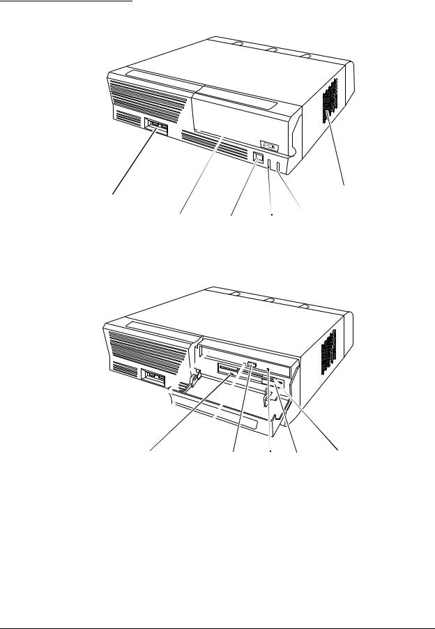
Part Names for IM-800
Front view
USB ports |
|
Ventilation |
|
opening |
|
CD/FDD |
Power |
Power HDD LED |
cover |
switch |
LED |
With CD/FDD cover open
CD-ROM |
FDD LED CD-ROM |
CD-ROM Eject FDD unit |
FDD eject |
drive(option) |
LED |
eject button hole |
button |
Rev. I |
Features and Overview 1-3 |

Rear Cover
Rear cover
Rear view(Standard model)
COM2 port |
PCI slot COM3 port DC 12V output |
AC voltage |
|||
|
|
|
|
(for DM-M820) |
select switch |
|
|
|
|
|
|
|
|
|
|
|
|
|
|
|
|
|
|
Mouse |
COM1 port |
Display |
|
Line-out |
Line-in |
Mic input |
|
|
|
|
|
||||||
|
AC Inlet |
|||||||
|
|
port |
|
output |
input |
|
||
|
|
|
|
|
|
|||
Keyboard |
LPT port |
Ethernet |
|
|
|
COM4 port |
|
|
|
|
port |
|
|
|
|
|
|
|
|
USB port |
|
|
|
|
||
|
|
|
|
|
|
|
||
Rear view(24V model)
DC 24V output |
COM2 port |
PCI slot COM3 port |
|||||
(for TM printer) |
|
|
|
|
|
DC 12V output |
|
|
|
|
|||||
|
|
|
|
|
|
|
|
|
|
|
|
|
|
|
|
|
|
|
|
|
|
|
|
|
|
|
|
|
|
|
|
Mouse |
COM1 port |
Display |
|
Line-out |
Line-in |
Mic input |
|
|
|
|
|
||||||
|
AC Inlet |
|||||||
|
|
port |
|
output |
input |
|
||
|
|
|
|
|
|
|||
Keyboard |
LPT port |
Ethernet |
|
|
|
COM4 port |
|
|
|
|
port |
|
|
|
|
|
|
|
|
USB port |
|
|
|
|
||
|
|
|
|
|
|
|
||
1-4 Features and Overview |
Rev. I |
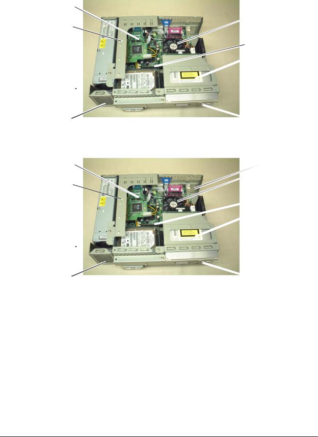
.
Inside view(for the Standard model)
COM Port Circuit 
Board Assembly
PCI card
Power Supply
HDD 
Speaker
(for the Speaker model)
Inside view(for the 24V model)
COM Port Circuit 
Board Assembly
PCI card
Power Supply
HDD 
Speaker
(for the Speaker model)
Rear Side
Front Side
Rear Side
Front Side
MR Series Technical Reference Manual
 CPU
CPU
 DIMM
DIMM
 CD-ROM Drive
 FDD
FDD
 DC 24V Board
 CPU
CPU
 DIMM
DIMM
 CD-ROM Drive
 FDD
FDD
Rev. I |
Features and Overview 1-5 |
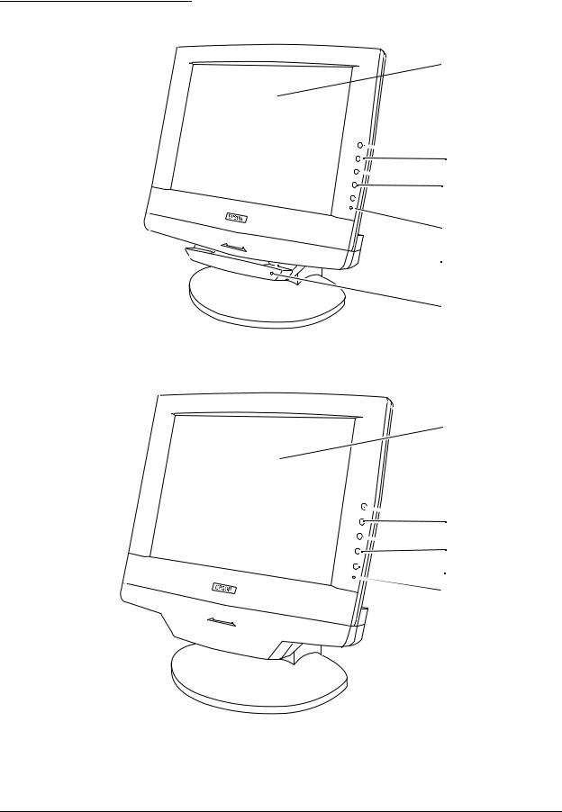
Part Names for DM-M820
Model with MSR
MSR unit**
Model without MSR
LCD / touch panel*
 Function control buttons
 Adjustment control

 Power switch
 Power-On LED
 Card Slot**
 LED for MSR**
LCD / touch panel*
 Function control buttons
 Adjustment
control  Power switch
Power-On LED
1-6 Features and Overview |
Rev. I |
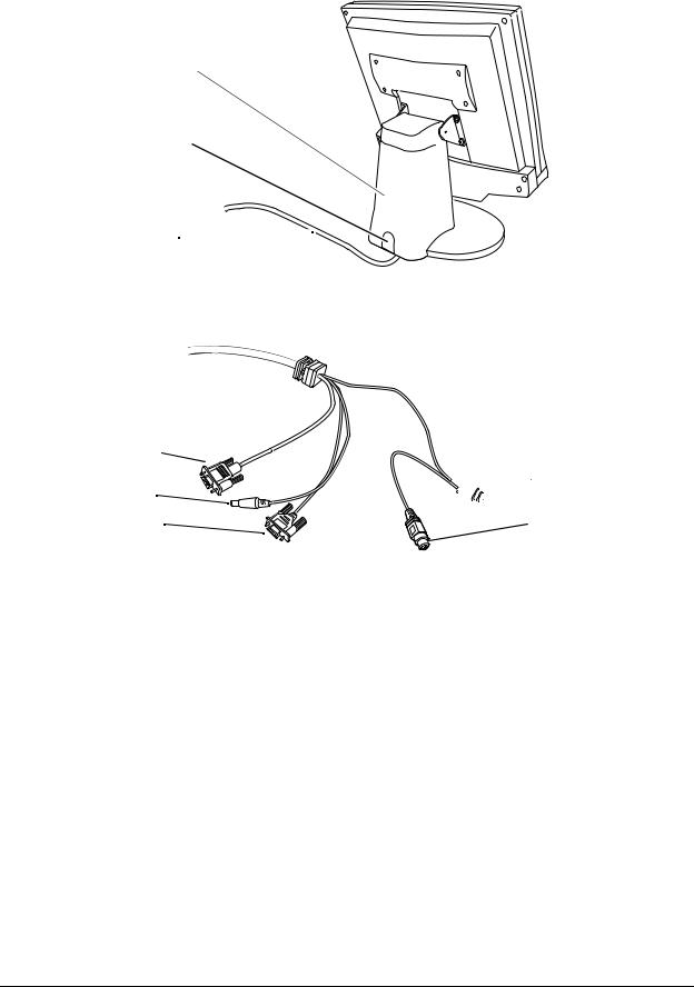
Rear view
LCD stand
Stand tab 
Cable A /
Cable B /
Cable C /
Cable A (with a touch panel and an MSR)
Display connector
DC plug
Serial port connector
MR Series Technical Reference Manual
PS/2 keyboard 
 connector for IM-800
PS/2 keyboard connector for keyboard
Rev. I |
Features and Overview 1-7 |
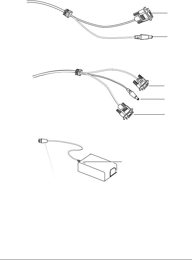
Cable B (without a touch panel and an MSR)
Display connector
DC plug
Cable C (with a touch panel, without an MSR)
Serial port connector
DC plug
Display connecter
.
AC Adapter (OI-MR01)
Power LED
 AC inlet
DC plug
*Applies only to models with a touch panel.
**Applies only to models with an MSR.
1-8 Features and Overview |
Rev. I |

|
|
|
|
|
|
MR Series Technical Reference Manual |
|
|
|
|
|
|
|
Specifications |
|
|
||||
IM-800 |
|
|
||||
|
|
|
|
|
|
|
|
|
|
|
|
Item |
Specifications |
|
|
|
|
|
||
|
|
CPU |
|
Usable CPU types *1) |
Celeron 733 MHz or 1.2 GHz |
|
|
|
|
|
|
|
|
|
|
|
|
|
Socket |
370-pin socket |
|
|
|
|
|
|
|
|
|
Memory |
|
Main memory *2) |
168-pin DIMM slots × 2 |
|
|
|
|
|
|
|
3.3V PC100 SDRAM / Maximum 512MB |
|
|
|
|
|
|
|
|
|
|
|
|
BIOS ROM |
512KB |
|
|
|
|
|
|
|
|
|
Chipset |
|
Intel 810E2 chipset |
||
|
|
|
|
|
||
|
|
Video controller |
|
Built-in chipset |
||
|
|
|
|
|
||
|
|
IO controller |
|
Winbond W83627F (controls FDD, COM1/2, PS/2, and parallel |
||
|
|
|
|
|
|
interface) |
|
|
|
|
|
|
ITE IT8872F (controls COM3/4) |
|
|
|
|
|
||
|
|
Mass storage |
|
FDD |
One 3.5" floppy drive (1.44MB / 720KB) |
|
|
|
|
|
|
|
|
|
|
|
|
|
HDD |
One 3.5" HDD or Two 2.5" HDD |
|
|
|
|
|
|
IDE interface / Ultra DMA/33/66/100 |
|
|
|
|
|
|
|
|
|
|
|
|
CD-ROM drive |
A CD-ROM or CD-R/RW optionally installed in factory, IDE |
|
|
|
|
|
|
interface, can be set as boot drive |
|
|
|
|
|
|
|
|
|
Interface |
|
LAN (Ethernet) |
10BASE-T/100BASE-TX is installed, "Wake On LAN" is |
|
|
|
|
|
|
|
supported. |
|
|
|
|
|
|
|
|
|
Interface |
|
Keyboard |
One PS/2-type (6-pin mini-DIN) |
|
|
|
|
|
|
|
|
|
|
|
|
|
Mouse |
One PS/2-type (6-pin mini-DIN) |
|
|
|
|
|
|
|
|
|
|
|
|
Serial *3) |
Four ports (9-pin D-sub male) |
|
|
|
|
|
|
+5V or +12V can be output to COM3 or COM4. |
|
|
|
|
|
|
|
|
|
|
|
|
Parallel |
One port (D-sub 25-pin female) SPP/EPP/ECP supported |
|
|
|
|
|
|
|
|
|
|
|
|
Display |
One port (D-sub 15-pin female) |
|
|
|
|
|
|
|
|
|
|
|
|
USB *4) |
Two ports on the front and two ports on the rear. |
|
|
|
|
|
|
|
|
|
|
|
|
Audio |
LINE IN, LINE OUT, microphone terminals |
|
|
|
|
|
|
|
|
|
|
|
|
DC12V output *5) *8) |
One (+12V / 3A) for DM-M820 |
|
|
|
|
|
|
|
|
|
|
|
|
DC 24V output*8) |
One (+24V / 2A) for EPSON TM Printer |
|
|
|
|
|
|
|
|
|
Expansion slot |
|
PCI slot |
One slot (PCI version 2.2 compliant) |
|
|
|
|
|
|
|
|
|
|
Internal speaker *6) |
|
Built-in monaural speaker |
||
|
|
|
|
|
||
|
|
Audio function *6) |
|
AC'97 audio CODEC supported |
||
|
|
|
|
|
|
External line input/output, with a microphone terminal |
|
|
|
|
|
||
|
|
Backup battery |
|
For the Lithium non-rechargeable battery the RTC and the |
||
|
|
|
|
|
|
RTC's built-in CMOS RAM when AC power is not supplied. |
|
|
|
|
|
|
Battery type: CR2032 |
|
|
|
|
|
|
Battery life: Approximately 5 years |
|
|
|
|
|
||
|
|
BIOS |
|
ACPI 1.0b / APM 1.2 / Plug & Play / DMI |
||
|
|
|
|
|
|
Diagnostics Utility are supported |
|
|
|
|
|
||
|
|
OS *7) |
|
MS-DOS, Windows 98, Windows NT, Windows 2000, Windows XP |
||
|
|
|
|
|
|
|
Rev. I |
Features and Overview 1-9 |

|
Item |
|
|
Specifications |
|
|
|
|
|
|
|
Lithium battery |
|
|
|
The IM-800 is internally equipped with a Lithium non-rechargeable |
|
|
|
|
|
battery that supplies the backup voltage to the RTC and the RTC's built- |
|
|
|
|
|
in CMOS RAM when AC power is not supplied. The battery can be |
|
|
|
|
|
exchanged easily because the battery is connected through the |
|
|
|
|
|
socket. |
|
|
|
|
|
Battery type: |
CR2032 |
|
|
|
|
Battery life: Approximately 5 years |
|
|
|
|
|
|
|
Power supply |
Standard |
|
|
145W ATX power supply is built in |
|
|
model |
|
|
|
|
|
Input voltage *8) |
AC input voltage can be changed with a switch. |
|||
|
|
||||
|
|
|
|
Low range: 100-127 VAC / 3.5 A (max.) |
|
|
|
|
|
High range: 200-240 VAC / 2 A (max.) |
|
|
|
|
|
|
|
|
|
Frequency |
50 / 60 Hz |
|
|
|
|
|
|
|
|
|
24V |
|
|
180W ATX power supply is built in |
|
|
model |
|
|
|
|
|
Input voltage *8) |
100-127 VAC / 4 A (max.) |
|||
|
|
||||
|
|
|
|
200-240 VAC / 2 A (max.) |
|
|
|
|
|
|
|
|
|
Frequency |
50 / 60 Hz |
|
|
|
|
|
|
|
|
Case |
Size |
|
315(W) × 280(D) × 88(H) mm (excluding the rear cover) |
||
|
|
|
|
{12.4 × 11 × 3.5"} |
|
|
|
|
|
315(W) × 365(D) × 88(H) mm (including the rear cover) |
|
|
|
|
|
{12.4 × 14.4 × 3.5"} |
|
|
|
|
|
||
|
Color |
|
Epson cool white |
||
|
|
|
|
Epson dark gray |
|
|
|
|
|
|
|
Environmental |
Condition: |
Operating range |
Storage range |
||
conditions |
Temperature: |
5 to 35°C {41 to 95°F} |
–10 to 50°C {14 to 122°F} |
||
|
Humidity (RH): 30 to 80% non-condensing |
30 to 90% non-condensing |
|||
|
|
|
|
|
|
*1: The Celeron (533 MHz or less) with a PPGA package is not supported. *2: ECC is not supported.
*3: If the COM3/4 is used, you need to install the serial driver from the Driver CD-ROM for the IM-800.
*4: The USB interface is not supported with MS-DOS, or Windows NT. (The keyboard or mouse is supported with the BIOS.) *5: The LCD outlet must not be connected to a peripheral other than the DM-M820.·
*6: The internal speaker is not supported by the onboard sound controller.(There is a model that can output sound through the internal speaker.)
*7: There are some limitations with each OS. Refer to Chapter 4 “OS and Drivers.” *8: A switch to cut the AC power off is not available.
1-10 Features and Overview |
Rev. I |
Loading...