


Installation Guide 
Guide d’installation 
Guía de instalación 
English |
Français |
Español |
Safety Instructions
For your safety, read all the instructions in this guide before using the setting plate. Incorrect handling that ignores instructions in this guide could damage the setting plate or could result in personal injury or property damage. Keep this installation guide at hand for future reference.
Read the User's Guide and Safety Instructions for your projector and follow the instructions in these documents.
Explanation of Symbols
The warning marks shown below are used throughout this installation guide to prevent personal injury or property damage. Make sure you understand these warnings when reading this installation guide.
Warning |
This symbol indicates information that, if ignored, could possibly result in personal injury or even death |
|
due to incorrect handling. |
||
|
|
|
Caution |
This symbol indicates information that, if ignored, could possibly result in personal injury or physical |
|
damage due to incorrect handling. |
||
|
This symbol indicates related or useful information.
Symbol indicating an action that must not be done
Symbol indicating an action that should be done
Safety Precautions for Installation
 Warning
The setting plate is designed specifically for mounting a projector to a wall. If anything other than a projector is mounted, the weight may result in damage.
If the setting plate falls, it could cause personal injury or property damage.
The installation work (wall mounting) should be performed by specialists who have technical knowledge and ability. Incomplete or incorrect installation could cause the setting plate to fall and cause personal injury or property damage.
Follow the instructions in this guide when installing the setting plate.
If the instructions are not followed, the setting plate may fall, resulting in personal injury or an accident.
Handle the power cord carefully.
Incorrect handling may cause fire or electric shock. Observe the following precautions when handling:
•Do not handle the power plug with wet hands.
•Do not use a power cord that is damaged or modified.
•Do not pull the power cord with too much force when routing the cable through the setting plate.
Do not install the setting plate in a place where it might be subjected to vibration or shock.
Vibration or shock could cause damage to the projector or mounting surface. It could also cause the setting plate or projector to fall and cause personal injury or property damage.
Install the setting plate so that it can sufficiently support the mass of the projector and setting plate, and resist any horizontal vibration. Use M8 nuts and bolts.
Nuts and bolts smaller than M8 could cause the setting plate to fall. Epson accepts no responsibility for any damage or injury caused by lack of wall strength or inadequate installation.
The installation work should be performed by at least two qualified service personnel. If you need to loosen any screws during installation, be careful not to drop the setting plate.
If the setting plate or projector falls, it could cause personal injury or property damage.
2
Warning |
|
|
When you mount the projector on the wall with the setting plate, the wall requires enough strength to hold |
English |
|
the projector and the setting plate. |
||
|
||
This setting plate should be installed on a concrete wall. Confirm the weight of the projector and the |
|
|
setting plate before installation, and maintain the strength of the wall. If the wall is not strong enough, |
|
|
reinforce the wall before installation. |
|
|
Inspect the setting plate on a regular basis to ensure there are no broken parts or loose screws. |
|
If there are any broken parts, stop using the setting plate immediately. If the setting plate or projector falls, it could cause personal injury or property damage.
Never modify the setting plate.
Do not hang on the setting plate or hang a heavy object on the setting plate.
If the projector or setting plate falls, it could cause personal injury or property damage.
If you use adhesives to prevent the screws from loosening or things such as lubricants or oils on the slide plate fixing part of the projector, the case may crack and cause the projector to fall, resulting in personal injury or property damage. Do not use adhesives, lubricants, or oils to install or adjust the setting plate.
Tighten all screws firmly after adjustment.
Otherwise, the projector or setting plate may fall and cause personal injury or property damage.
Never loosen the bolts and nuts after installation.
Confirm that the screws have not become loose on a regular basis. If you find any loose screws, tighten them firmly.
Otherwise, the projector or setting plate may fall and cause personal injury or property damage.
When performing wiring, make sure the cable does not come into contact with any screws or bolts.
Handling the cable incorrectly may cause fire or electric shock.
 Caution
Do not install the setting plate in a location where the operating temperature for your projector model may be exceeded.
Such an environment may damage the projector.
Install the setting plate in a place free from excessive dust and humidity to prevent the lens or optical components from becoming dirty.
Do not use excessive force when adjusting the setting plate.
The setting plate may break, resulting in personal injury.
3

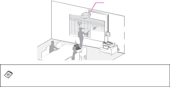
Place to Install the Setting Plate
Carry out the power supply wiring work for the installation location of the setting plate in advance.
Install the projector away from other electric devices such as fluorescent lights or air conditioners. Some kinds of fluorescent lights could interfere with the remote control of the projector.
It is recommended to keep connection cable length less than 20 meters to reduce external noise.
We recommend using stick-on screens or board screens.
Make sure the projector is setup under the following conditions.
•The projection screen is a rectangular shape without any distortion.
•The projector is tilted at an angle of no more than ±3° vertically and horizontally in relation to the projection surface.
By using the interactive function (Easy Interactive Function), you can make notes directly on the projection surface with the Easy Interactive Pen. Set up so that the projection surface is within arms reach.
If multiple EB-1410Wi or EB-1400Wi are installed in the same room, Easy Interactive Pen operations may become unstable. Set [Distance of Projectors] from the Configuration menu according to the distance between the projectors.
s Projector's User's Guide "Configuration Menu"
About This Installation Guide
This guide describes how to mount the short-throw projector EB-1410Wi/1400Wi to a wall using the exclusive setting plate.
4
1 |
Package Contents |
s p. 6 |
|
2 |
Specifications |
s p. 7 |
English |
|
|||
3 |
Connecting Devices |
s p. 9 |
|
4 |
Projection Distance Table |
s p. 11 |
|
|
|
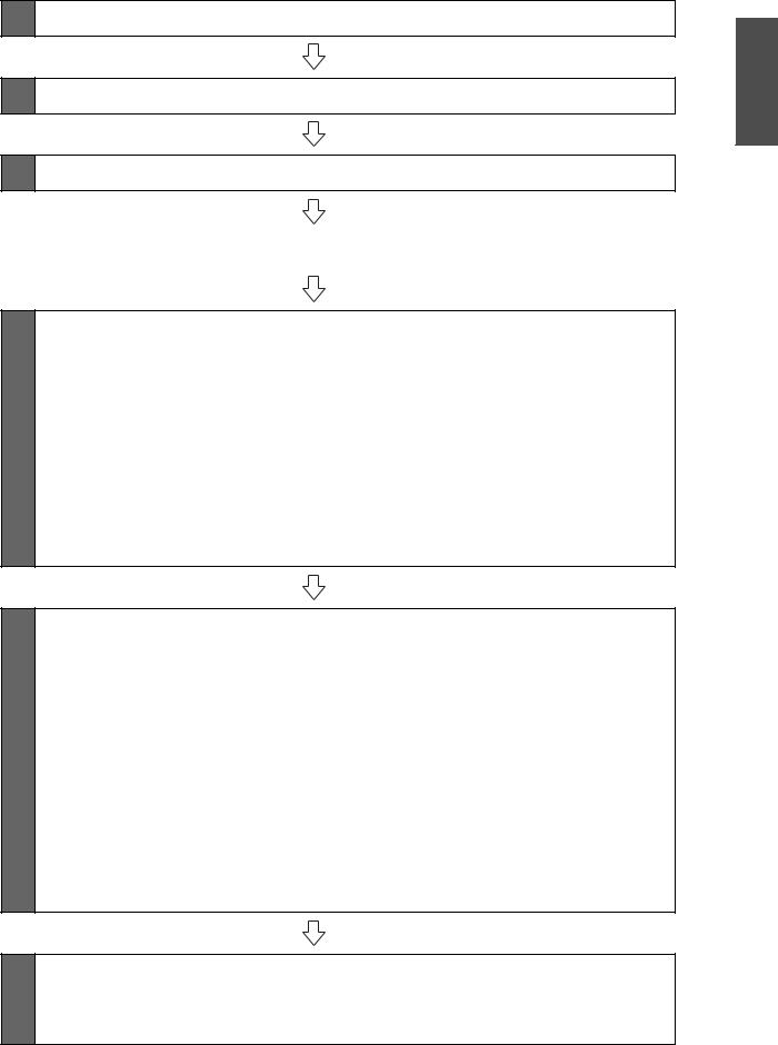
5 Installation Procedure |
s p. 17 |
(1)Disassemble the parts
(2)Assemble the parts
(3)Install the wall plate on the wall
(4)Determine the projection distance and pull out the slider
(5)Route the cables through the setting plate
(6)Attach the setting plate to the wall plate
(7)Adjust the vertical slide to align it with the standard position
(8)Secure the projector to the setting plate
(9)Connect the power cord and other cables to the projector
6 Adjusting the Projection Screen |
s p. 27 |
(1)Turn on the projector
(2)Change the aspect ratio
(3)Display the test pattern
(4)Adjust the focus
(5)Use the left adjustment dial to adjust the horizontal roll
(6)Use the right adjustment dial to adjust the horizontal rotation
(7)Use the top adjustment dial to adjust the vertical tilt
(8)Adjust the horizontal slide
(9)Adjust the forward/backward slide
(10)Adjust the vertical slide
(11)Turn off the display of the test pattern
7 Attaching the Covers |
s p. 33 |
(1)Attach the wall plate cover and end cap
(2)Attach the cable cover to the projector
5
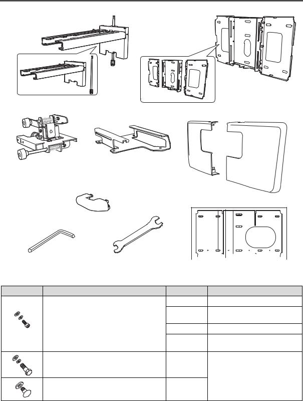
1. Package Contents
Setting plate
Wall plate
3-axis adjustment unit |
Slide plate |
* The slide plate is secured to the 3-axis adjustment unit when shipped.
Wall plate cover
End cap
Hexagon wrench (for M4) |
Open-ended spanner |
|
|
|
|
|
|
|
|
|
|
|
|
|
|
|
|
|
|
|
|
|
|
|
|
|
|
|
|
|
|
|
|
|
|
|
|
|
|
|
|
|
|
|
|
|
|
|
|
|
|
||
|
|
|
|
|
|
|
|
|
|
|
|
|
|
|
|
|
|
|
|
|
|
|
|
|
||
|
|
|
|
|
|
|
|
|
|
|
|
|
|
|
|
|
|
|
|
|
|
|
|
|
||
|
|
|
|
|
|
|
|
|
|
|
|
|
|
|
|
|
|
|
|
|
|
|
|
|
||
|
|
|
|
|
|
|
|
|
|
|
|
|
|
|
|
|
|
|
|
|
|
|
|
|
||
|
13 mm (for M8 and M6) x |
|
|
|
|
|
|
|
Template sheet |
|||||||||||||||||
|
|
|
|
|
(for installing the wall plate) |
|||||||||||||||||||||
|
6 mm (for hexagonal axis) |
|
|
|
|
|||||||||||||||||||||
|
|
|
|
|
|
|
|
|
|
|
|
|
|
|
|
|
|
|
|
|
|
|
|
|
|
|
Shape |
Name |
Quantity |
Application |
|
M4 x 12 mm hexagon socket head cap bolt with |
6 |
For wall plate assembly |
|
washer/spring washer |
4 |
For 3-axis adjustment unit/setting |
|
|
||
|
|
|
plate installation |
|
|
4 |
For slide plate/projector installation |
|
|
2 |
For slide plate/3-axis adjustment unit |
|
|
|
installation (secured when shipped) |
|
M6 x 20 mm hexagon shoulder bolt with washer/ |
1 |
For setting plate/wall plate installation |
|
spring washer |
|
|
|
M6 x 20 mm cross recessed head shoulder screw |
3 |
|
|
with plastic washer |
|
|
Use the bolts or screws supplied with the setting plate to install it as directed in this guide. Do not substitute these bolts with any other types.
You need to use commercially available M8 x 50 mm anchors (at least 3) to attach the wall plate to the wall.
Gather the tools and parts you need before you begin installation.
6
2. Specifications |
|
|
|
|
Item |
Specification |
Remark |
Reference |
English |
|
||||
|
|
|
Page |
|
Setting plate mass (including the |
Approx. 7.4 kg |
Setting plate (2.8 kg), 3-axis adjustment unit (1.1 kg), |
|
|
3-axis adjustment unit, slide plate, |
|
slide plate (0.7 kg), wall plate (2.5 kg), wall plate cover |
|
|
wall plate, wall plate cover, and |
|
and end cap (0.3 kg) |
|
|
end cap) |
|
|
|
|
Maximum load capacity |
7 kg |
|
|
|
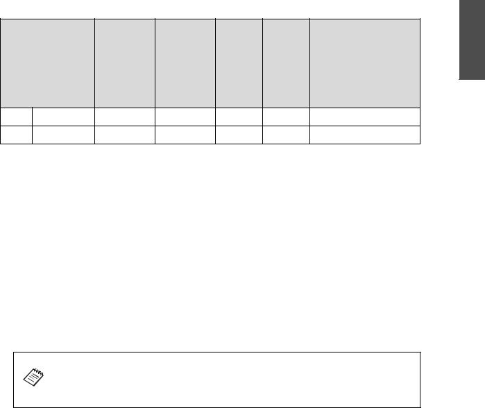
Forward/backward slide |
0 to 310 mm |
Arm slide adjustment range: 0 to 248 mm |
Refer to the |
|
adjustment range |
|
Adjustment from 3-axis adjustment unit installation |
figure below |
|
|
|
position: 62 mm |
|
|
Vertical slide adjustment range |
± 38 mm |
|
Refer to the |
|
|
|
|
figure below |
|
Horizontal roll adjustment range |
± 3° |
Fine adjustments possible with adjustment dial |
s p. 29 |
|
Horizontal rotation adjustment |
± 3° |
Fine adjustments possible with adjustment dial |
s p. 30 |
|
range |
|
|
|
|
Vertical tilt adjustment range |
± 3° |
Fine adjustments possible with adjustment dial |
s p. 30 |
|
Horizontal slide adjustment range |
± 45 mm |
|
Refer to the |
|
|
|
|
figure below |
|
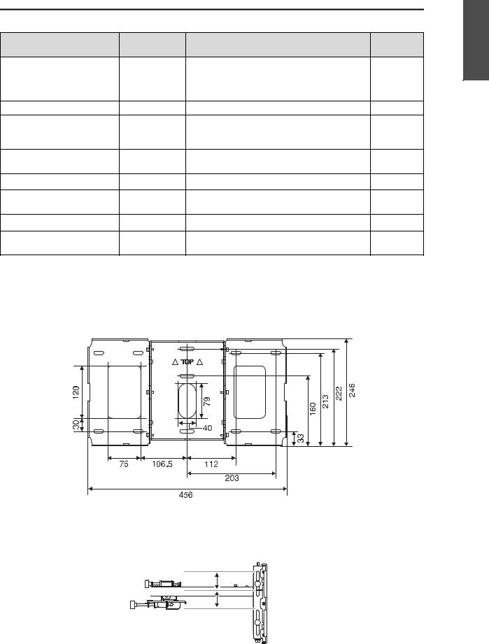
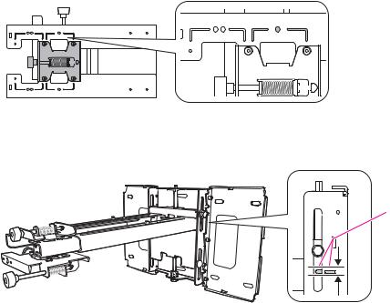
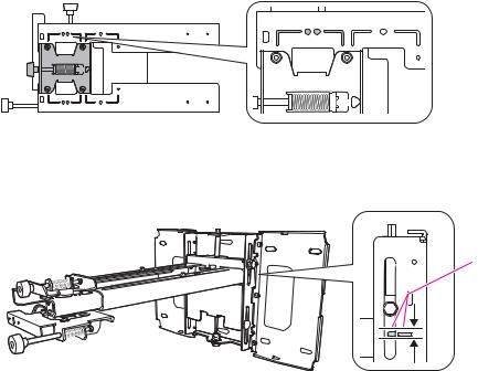
Wall plate
The product is in three piece when shipped. Use the M4 x 12 mm bolts (x6) supplied to screw the separate pieces together before use.
[Unit: mm]
Vertical slide adjustment range
38 mm
38 mm |
7
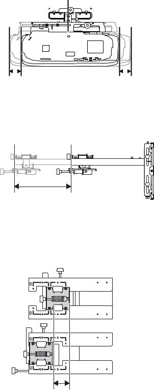
Horizontal slide adjustment range
|
|
|
|
|
|
|
|
|
|
|
|
|
|
|
|
|
|
|
|
|
|
|
|
|
|
|
|
|
|
|
|
|
|
|
|
|
|
|
|
|
|
|
|
|
|
|
|
|
|
|
|
|
|
|
|
|
|
|
|
|
|
|
|
|
|
|
|
|
|
|
|
|
|
|
|
|
|
|
|
|
|
|
|
|
|
|
|
|
|
|
|
|
|
|
|
|
|
|
|
|
|
|
|
|
|
|
|
|
|
|
|
|
|
|
|
|
|
|
|
|
|
|
|
|
|
|
|
|
|
|
|
|
|
|
|
|
|
|
|
|
|
|
|
|
|
|
|
|
|
|
|
|
|
|
|
|
|
|
|
|
|
|
|
|
|
|
|
|
|
|
|
|
|
|
|
|
|
|
|
|
|
|
|
|
|
|
|
|
|
|
|
|
|
|
|
|
|
|
|
|
|
|
|
|
|
|
|
|
|
|
|
|
|
|
|
|
|
|
|
|
|
|
|
|
|
|
|
|
|
|
|
|
|
|
|
|
|
|
|
|
|
|
|
|
|
|
|
|
|
|
|
|
|
|
|
|
|
|
|
|
|
|
|
|
|
|
|
|
|
|
|
|
|
|
|
|
|
|
|
|
|
|
|
|
|
|
|
|
|
|
|
|
|
|
|
|
|
|
|
|
|
|
|
|
|
|
|
|
|
|
|
|
|
|
|
|
|
|
|
|
|
|
|
|
|
|
|
|
|
|
|
|
|
|
|
|
|
|
|
|
|
|
|
|
|
|
|
|
|
|
|
|
|
|
|
|
|
|
|
|
|
|
|
|
|
|
|
|
|
|
|
|
|
|
|
|
|
|
|
|
|
|
|
|
|
|
|
|
|
|
|
|
|
|
|
|
|
|
|
|
|
|
|
|
|
|
|
|
|
|
|
|
|
|
|
|
|
|
|
|
|
|
|
|
|
|
|
|
|
|
|
|
|
|
|
|
|
|
|
|
|
|
|
|
|
|
|
|
|
|
|
|
|
|
|
|
|
|
|
|
|
|
|
|
|
|
|
|
|
|
|
|
|
|
|
|
|
|
|
|
|
|
|
|
|
|
|
|
|
|
|
|
|
|
|
|
|
|
|
|
|
|
|
|
|
|
|
|
|
|
|
|
|
|
|
|
|
|
|
|
|
|
|
|
|
|
|
|
|
|
|
|
|
|
|
|
|
|
|
|
|
|
|
|
|
|
|
|
|
|
|
|
|
|
|
|
|
|
|
|
|
|
|
|
|
|
|
|
|
|
|
|
|
|
|
|
|
|
|
|
|
|
|
|
|
|
|
|
|
|
|
|
|
|
|
|
|
|
|
|
|
|
|
|
|
|
|
|
|
|
|
|
|
|
|
|
|
|
|
|
|
|
|
|
|
|
|
|
|
|
|
|
|
|
|
|
|
|
|
|
|
|
|
|
45 mm |
|
|
|
|
|
|
|
|
|
|
|
|
|
|
|
|
|
|
|
|
|
|
|
|
|
|
|
|
|
|
|
|
45 mm |
|||||||||
Forward/backward slide adjustment range
Arm slide adjustment range
248 mm |
Adjustment from 3-axis adjustment unit installation position
By changing the installation position of the 3-axis adjustment unit to the front or back, you can adjust the installation position of the projector.
When the screen size is less than 70 inches, install it at the position marked with a  stamp. When the screen size is 70 inches or more, install it at the position marked with a
 stamp.
62 mm
8
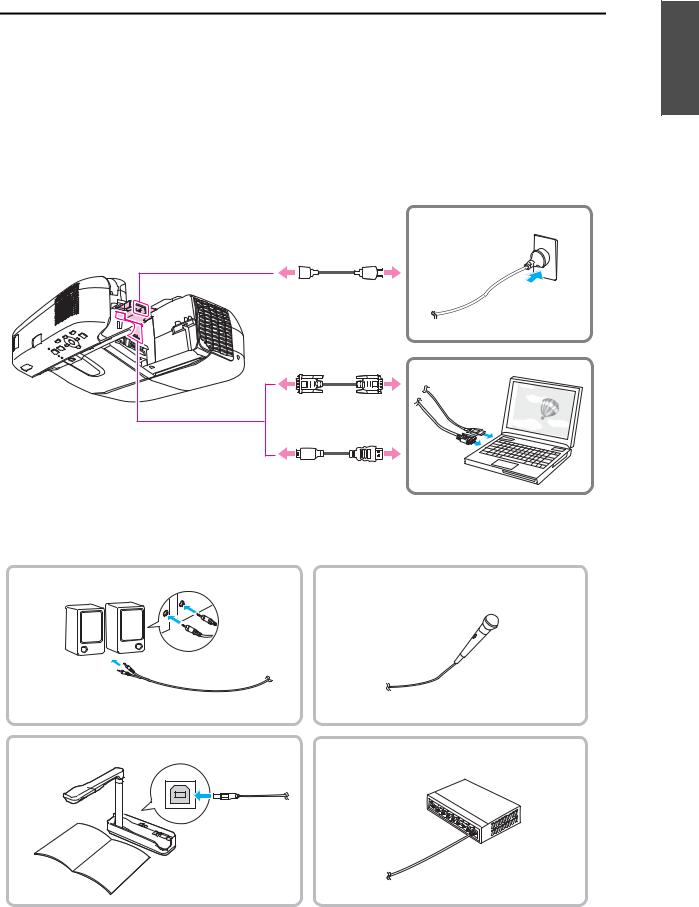
3. Connecting Devices |
English |
|
Necessary Cables |
||
|
||
Prepare all necessary cables at the location where the setting plate is to be installed. |
|
|
Power cord, computer cable, USB cable (required) |
|
|
Cables for devices, such as a document camera or microphone, that you will connect to the projector |
|
|
(depending on your needs) |
|
For details, refer to the supplied User's Guide on the Document CD-ROM.
Required cables
Power cord
Computer cable
(for computer video output)
USB cable
(for interactive function)
Prepare cables for your devices
External speakers |
Microphone |
Audio cable (commercially available product)
Document camera
LAN device
Dedicated USB cable |
LAN cable (commercially |
|
available product) |
||
(supplied with document camera) |
||
|
9
Control Pad
The Control Pad is supplied with EB-1410Wi/1400Wi projectors. By installing the Control Pad, you can easily perform frequently used operations such as turning the projector on and off, changing the source, and so on. You can also connect a USB memory, a printer's USB cable, and so on to the Control Pad.
Installation example
Projector
xxx |
|
|
|
|
xxx |
90000 |
90000 |
|
|
|
80000 |
▲300 |
||
|
|
180000 |
▲200 |
90000 |
|
|
|
||
|
|
|
|
80000 |
xxx |
80000 |
xxx |
▲300 |
xxx |
90000 |
xxx |
80000 |
xxx |
▲300 |
|
▲300 |
 Control Pad
 Printer
If you want to use the Control Pad, you also need to consider the installation position of the Control Pad before you start installing the projector. The Control Pad has its own recommended installation range and requirements. See the printed material or the "Control Pad Installation Guide" on the Document CD-ROM supplied.
10
4. Projection Distance Table |
|
English |
|
Refer to the table below and install the setting plate and projector to project images at an appropriate size on |
|||
|
|||
the projection surface. The values are only rough estimates. |
|
|
|
The recommended range for the projection distance (a) is 62 to 311 mm. |
|
||
The numbers on the slider measure (b) are the same as the projection distance (a) when the screen size (S) is |
|
||
70 inches or more. Because the installation position of the projector changes when S is less than 70 inches, the |
|
||
numbers for a and b differ. |
|
|
|
70.5 mm |
Offset value for the position of the |
|
|
center of the screen and the center of |
|
||
|
|
||
|
the wall plate |
|
|
218 mm |
Wall plate |
|
|
|
|
||
|
Projection surface |
|
|
Distance from wall of |
|
|
|
projection surface |
|
|
|
11
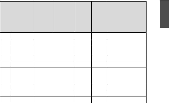
When the screen size is less than 70 inches
Mount the 3-axis adjustment unit at the position marked with a  stamp.
The table below provides the figures when mounting the 3-axis adjustment unit at the position marked with a  stamp. The numbers on the slider measure (b) differ from the projection distance (a).
The distance (c) from the projection screen to the wall plate is the number given when the vertical slide is set to the standard position.
Match the notch on the setting plate to the position of the stamp on the wall plate.
Standard position
4:3 aspect ratio |
|
|
|
|
[Unit: cm] |
||
|
|
S |
a |
b |
c |
h |
|
|
Screen Size |
Projection |
Numbers on |
Distance |
Height of |
|
|
|
|
|
Distance |
the Slider |
Between |
Projection |
Interactive Whiteboard |
|
|
|
Minimum |
Measure |
Projection |
Surface |
|
|
|
|
|
||||
|
|
|
(Wide) to |
|
Surface |
|
|
|
|
|
Maximum |
|
and Wall |
|
|
|
|
|
(Tele) |
|
Plate |
|
|
|
|
|
|
|
|
|
|
53" |
|
107.7 x 80.8 |
6.2 - 19.3 |
12.4 - 25.5 |
17.4 |
80.8 |
|
|
|
|
|
|
|
|
|
57" |
|
115.8 x 86.9 |
9.1 - 23.1 |
15.3 - 29.3 |
18.6 |
86.9 |
PolyVision TS410 |
|
|
|
|
|
|
|
|
60" |
|
122.0 x 91.4 |
11.2 - 25.9 |
17.4 - 32.1 |
19.5 |
91.4 |
HitachiCambridge board60 |
|
|
|
|
|
|
|
RM Classboard 60 |
|
|
|
|
|
|
|
INTERWRITE® BOARD 1060 |
|
|
|
|
|
|
|
INTERWRITE Dual board 1260 |
|
|
|
|
|
|
|
|
63" |
|
128.0 x 96.0 |
13.3 - 28.8 |
19.5 - 35.0 |
20.4 |
96.0 |
Hitachi Starboard FX DUO 63 |
|
|
|
|
|
|
|
|
64" |
|
130.0 x 97.5 |
14.0 - 29.7 |
20.2 - 35.9 |
20.7 |
97.5 |
SmartBoard660 |
|
|
|
|
|
|
|
ActivBoard 164 |
|
|
|
|
|
|
|
|
66" |
|
134.2 x 100.6 |
15.4 - 30.7 |
21.6 - 36.9 |
21.3 |
100.6 |
TeamBoard RT TMWM5422CL/ |
|
|
|
|
|
|
|
EM |
|
|
|
|
|
|
|
|
69" |
|
140.3 x 105.2 |
17.5 - 30.7 |
23.7 - 36.9 |
22.2 |
105.2 |
|
|
|
|
|
|
|
|
|
The smallest screen size is 53".
12
16:10 aspect ratio |
|
|
|
|
[Unit: cm] |
|
|
S |
a |
b |
c |
h |
English |
|
|
|||||
|
Screen Size |
Projection |
Numbers on |
Distance |
Height of |
|
|
|
Distance |
the Slider |
Between |
Projection |
Interactive Whiteboard |
|
|
Minimum |
Measure |
Projection |
Surface |
|
|
|
|
||||
|
|
(Wide) to |
|
Surface |
|
|
|
|
Maximum |
|
and Wall |
|
|
|
|
(Tele) |
|
Plate |
|
|
60" |
129.3 x 80.8 |
6.2 - 19.3 |
12.4 - 25.5 |
17.4 |
80.8 |
|
69" |
148.6 x 92.9 |
11.8 - 26.8 |
18.0 - 33.0 |
19.8 |
92.9 |
|
The smallest screen size is 60".
16:9 aspect ratio |
|
|
|
|
[Unit: cm] |
||
|
|
S |
a |
b |
c |
h |
|
|
Screen Size |
Projection |
Numbers on |
Distance |
Height of |
|
|
|
|
|
Distance |
the Slider |
Between |
Projection |
Interactive Whiteboard |
|
|
|
Minimum |
Measure |
Projection |
Surface |
|
|
|
|
|
||||
|
|
|
(Wide) to |
|
Surface |
|
|
|
|
|
Maximum |
|
and Wall |
|
|
|
|
|
(Tele) |
|
Plate |
|
|
|
|
|
|
|
|
|
|
59" |
|
130.7 x 73.5 |
6.6 - 19.8 |
12.8 - 26.0 |
21.7 |
73.5 |
|
|
|
|
|
|
|
|
|
60" |
|
132.8 x 74.7 |
7.3 - 20.7 |
13.5 - 26.9 |
22.0 |
74.7 |
|
|
|
|
|
|
|
|
|
69" |
|
152.9 x 85.9 |
13.0 - 28.4 |
19.2 - 34.6 |
25.1 |
85.9 |
|
|
|
|
|
|
|
|
|
The smallest screen size is 59".
The value may differ depending on the location where you place the projector. When projecting in Tele, the quality of the projected images may decrease.
When projecting images at a 4:3 aspect ratio, the images are resized automatically and the quality of the projected images may decrease.
13
When the screen size is 70 inches or more
Mount the 3-axis adjustment unit at the position marked with a 
 stamp.
The table below provides the figures when mounting the 3-axis adjustment unit at the position marked with a 
 stamp. The numbers on the slider measure (b) are the same as the projection distance (a).
The distance (c) from the projection screen to the wall plate is the number given when the vertical slide is set to the standard position.
Match the notch on the setting plate to the position of the stamp on the wall plate.
Standard position
4:3 aspect ratio |
|
|
|
|
[Unit: cm] |
||
|
|
S |
a |
b |
c |
h |
|
|
Screen Size |
Projection |
Numbers on |
Distance |
Height of |
|
|
|
|
|
Distance |
the Slider |
Between |
Projection |
Interactive Whiteboard |
|
|
|
Minimum |
Measure |
Projection |
Surface |
|
|
|
|
|
||||
|
|
|
(Wide) to |
|
Surface |
|
|
|
|
|
Maximum |
|
and Wall |
|
|
|
|
|
(Tele) |
|
Plate |
|
|
|
|
|
|
|
|
|
|
70" |
|
142.2 x 106.7 |
18.2 - 31.1 |
22.5 |
106.7 |
|
|
|
|
|
|
|
|
|
|
77" |
|
156.4 x 117.3 |
23.1 - 31.1 |
24.7 |
117.3 |
HitachiCambridge board77 |
|
|
|
|
|
|
|
|
Hitachi Starboard FX DUO 77 |
|
|
|
|
|
|
|
SmartBoard680 |
|
|
|
|
|
|
|
SmartBoardX880 |
|
|
|
|
|
|
|
INTERWRITE® BOARD 1077 |
|
|
|
|
|
|
|
TeamBoard RT TMWM6250CL/ |
|
|
|
|
|
|
|
EM |
|
|
|
|
|
|
|
|
77.5" |
|
157.4 x 118.1 |
23.5 - 31.1 |
24.8 |
118.1 |
RM Classboard 77.5 |
|
|
|
|
|
|
|
|
|
78" |
|
158.5 x 118.9 |
23.8 - 31.1 |
25.0 |
118.9 |
PolyVision eno2610 |
|
|
|
|
|
|
|
|
PolyVision TS610 |
|
|
|
|
|
|
|
ActivBoard 178 |
|
|
|
|
|
|
|
|
79" |
|
160.6 x 120.4 |
24.5 - 31.1 |
25.3 |
120.4 |
INTERWRITE Dual board 1279 |
|
|
|
|
|
|
|
|
|
80" |
|
162.5 x 121.9 |
25.2 - 31.1 |
25.6 |
121.9 |
|
|
|
|
|
|
|
|
|
|
88" |
|
178.9 x 134.1 |
30.8 - 31.1 |
28.0 |
134.1 |
|
|
|
|
|
|
|
|
|
|
The largest screen size is 88".
14
16:10 aspect ratio |
|
|
|
|
[Unit: cm] |
|
|
|
S |
a |
b |
c |
h |
|
English |
|
Screen Size |
Projection |
Numbers on |
Distance |
Height of |
|
|
|
|
Distance |
the Slider |
Between |
Projection |
Interactive Whiteboard |
|
|
|
Minimum |
Measure |
Projection |
Surface |
||
|
|
|
|||||
|
|
(Wide) to |
|
Surface |
|
|
|
|
|
Maximum |
|
and Wall |
|
|
|
|
|
(Tele) |
|
Plate |
|
|
|
70" |
150.7 x 94.2 |
12.4 - 27.6 |
20.1 |
94.2 |
|
|
|
75" |
161.5 x 101.0 |
15.5 - 31.1 |
21.4 |
101.0 |
PolyVision eno2650 |
|
|
77.8" |
167.5 x 104.7 |
17.3 - 31.1 |
22.2 |
104.7 |
PolyVision TS600/TS620/ |
|
|
|
|
|
|
|
|
TSL620 |
|
80" |
172.3 x 107.7 |
18.7 - 31.1 |
22.7 |
107.7 |
|
|
|
85" |
183.1 x 114.4 |
21.8 - 31.1 |
24.1 |
114.4 |
TeamBoard RT TMWM7450EM |
|
|
87" |
187.3 x 117.1 |
23.0 - 31.1 |
24.6 |
117.1 |
SmartBoard685 |
|
|
|
|
|
|
|
|
SmartBoardX885 |
|
|
|
|
|
|
|
ActivBoard 387 |
|
|
|
|
|
|
|
ActivBoard 587 pro |
|
88" |
189.5 x 118.5 |
23.6 - 31.1 |
24.9 |
118.5 |
Hitachi Starboard FX DUO-88W |
|
|
90" |
193.9 x 121.2 |
24.9 - 31.1 |
25.4 |
121.2 |
|
|
|
100" |
215.4 x 134.6 |
|
31.1* |
28.1 |
134.6 |
|
|
The largest screen size is 100".
* Figure for Wide (maximum zoom).
16:9 aspect ratio |
|
|
|
|
[Unit: cm] |
||
|
|
S |
a |
b |
c |
h |
|
|
Screen Size |
Projection |
Numbers on |
Distance |
Height of |
|
|
|
|
|
Distance |
the Slider |
Between |
Projection |
Interactive Whiteboard |
|
|
|
Minimum |
Measure |
Projection |
Surface |
|
|
|
|
|
||||
|
|
|
(Wide) to |
|
Surface |
|
|
|
|
|
Maximum |
|
and Wall |
|
|
|
|
|
(Tele) |
|
Plate |
|
|
|
|
|
|
|
|
|
|
70" |
|
155.0 x 87.2 |
13.7 - 29.3 |
25.4 |
87.2 |
|
|
|
|
|
|
|
|
|
|
71" |
|
157.1 x 88.4 |
14.3 - 30.1 |
25.8 |
88.4 |
INTERWRITE® BOARD 1071 |
|
77" |
|
170.6 x 95.9 |
18.1 - 31.1 |
27.8 |
95.9 |
INTERWRITE Dual board 1277 |
|
|
|
|
|
|
|
|
|
80" |
|
177.0 x 99.6 |
20.0 - 31.1 |
28.9 |
99.6 |
RM Classboard 85 |
|
|
|
|
|
|
|
|
|
82" |
|
181.5 x 102.1 |
21.3 - 31.1 |
29.6 |
102.1 |
Hitachi Starboard FX-82Wide |
|
|
|
|
|
|
|
|
|
85" |
|
188.1 x 105.8 |
23.2 - 31.1 |
30.6 |
105.8 |
INTERWRITE® BOARD 1085 |
|
|
|
|
|
|
|
|
INTERWRITE Dual board 1285 |
|
|
|
|
|
|
|
|
90" |
|
199.3 x 112.1 |
26.4 - 31.1 |
32.3 |
112.1 |
|
|
|
|
|
|
|
|
|
|
94" |
|
208.2 x 117.1 |
29.0 - 31.1 |
33.7 |
117.1 |
SmartBoard690 |
|
|
|
|
|
|
|
|
|
95" |
|
210.4 x 118.3 |
29.6 - 31.1 |
34.0 |
118.3 |
INTERWRITE® BOARD 1095 |
|
|
|
|
|
|
|
|
INTERWRITE Dual board 1295 |
|
|
|
|
|
|
|
ActivBoard 395 |
|
|
|
|
|
|
|
ActivBoard 595 pro |
|
|
|
|
|
|
|
|
15

|
|
S |
a |
b |
c |
h |
|
|
Screen Size |
Projection |
Numbers on |
Distance |
Height of |
|
|
|
|
|
Distance |
the Slider |
Between |
Projection |
Interactive Whiteboard |
|
|
|
Minimum |
Measure |
Projection |
Surface |
|
|
|
|
|
||||
|
|
|
(Wide) to |
|
Surface |
|
|
|
|
|
Maximum |
|
and Wall |
|
|
|
|
|
(Tele) |
|
Plate |
|
|
|
|
|
|
|
|
|
|
97" |
|
214.8 x 120.8 |
30.9 - 31.1 |
34.7 |
120.8 |
|
|
|
|
|
|
|
|
|
|
The largest screen size is 97".
The value may differ depending on the location where you place the projector. When projecting in Tele, the quality of the projected images may decrease.
When projecting images at a 4:3 aspect ratio, the images are resized automatically and the quality of the projected images may decrease.
16
5. Installation Procedure |
English |
|
Make sure to follow the steps below to install the setting plate. If you ignore these steps, the setting plate |
||
|
||
could fall and cause personal injury or property damage. |
|
|
Warning |
|
|
When you mount the projector on the wall with the setting plate, the wall requires enough |
|
|
strength to hold the projector and the setting plate. |
|
|
This setting plate should be installed on a concrete wall. Confirm the weight of the |
|
|
projector and the setting plate before installation, and maintain the strength of the wall. If |
|
|
the wall is not strong enough, reinforce the wall before installation. |
|
|
The combined mass of the projector and the setting plate is 14.5 kg. |
|
|
Do not hang the rest of the cable over the setting plate. |
|
|
Install the setting plate so that it can sufficiently support the mass of the projector and |
|
|
setting plate, and resist any horizontal vibration. Use M8 nuts and bolts. Nuts and bolts |
|
|
smaller than M8 could cause the setting plate to fall. |
|
|
Epson accepts no responsibility for any damage or injury caused by lack of wall strength or |
|
|
inadequate installation. |
|
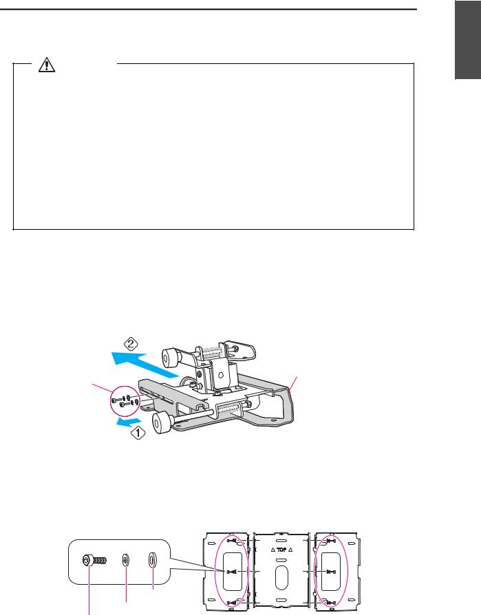
a Disassemble the parts
Remove the slide plate from the 3-axis adjustment unit.
•Remove the M4 x 12 mm hexagon socket head cap bolts (x2) ( ).
).
•Remove the slide plate from the 3-axis adjustment unit ( ).
).
M4 x 12 mm
Slide plate
hexagon socket
head cap bolts (x2)
b Assemble the parts
(1)Assemble the wall plate.
Assemble the three plates into one unit, and secure them with the M4 x 12 mm hexagon socket head cap bolts (x6) supplied.
Washer
Spring washer
M4 x 12 mm hexagon socket head cap bolts
17
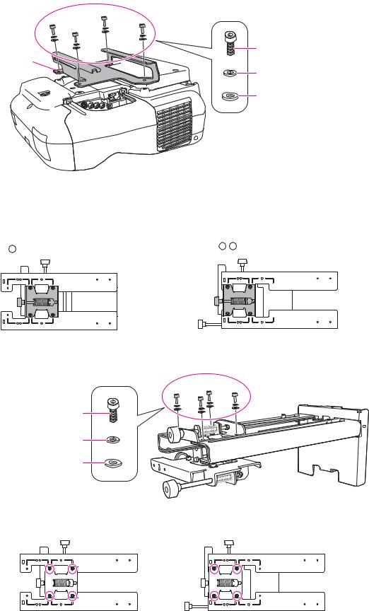
(2)Attach the slide plate to the projector.
Attach the slide plate to the projector using the M4 x 12 mm hexagon socket head cap bolts (x4) supplied.
Slide plate |
M4 x 12 mm hexagon socket head |
cap bolts |
|
|
Spring washer |
|
Washer |
(3)Attach the 3-axis adjustment unit to the setting plate.
•Decide which position you want to install the 3-axis adjustment unit.
Mount it at the  stamp when the projection screen is less than 70 inches, or mount it at the
 stamp when the screen is 70 inches or more.
: Less than 70 inches |
: 70 inches or more |
|
•Tighten the M4 x 12 mm hexagon socket head cap bolts (x4) supplied to install the 3-axis adjustment unit.
M4 x 12 mm hexagon socket head cap bolts
Spring washer
Washer
Bolt installation positions
When the projection screen is less than 70 inches |
When the projection screen is 70 inches or more |
|||||||||||||||||||||||||||
|
|
|
|
|
|
|
|
|
|
|
|
|
|
|
|
|
|
|
|
|
|
|
|
|
|
|
|
|
|
|
|
|
|
|
|
|
|
|
|
|
|
|
|
|
|
|
|
|
|
|
|
|
|
|
|
|
|
|
|
|
|
|
|
|
|
|
|
|
|
|
|
|
|
|
|
|
|
|
|
|
|
|
|
|
|
|
|
|
|
|
|
|
|
|
|
|
|
|
|
|
|
|
|
|
|
|
|
|
|
|
|
|
|
|
|
|
|
|
|
|
|
|
|
|
|
|
|
|
|
|
|
|
|
|
|
|
|
|
|
|
|
|
|
|
|
|
|
|
|
|
|
|
|
|
|
|
|
|
|
|
|
|
|
|
|
|
|
|
|
|
|
|
|
|
|
|
|
|
|
|
|
|
|
|
|
|
|
|
|
|
|
|
|
|
|
|
|
|
|
|
|
|
|
|
|
|
|
|
|
|
|
|
|
|
|
|
|
|
|
|
|
|
|
|
|
|
|
|
|
|
|
18
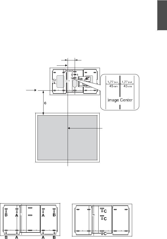
c Install the wall plate on the wall |
|
|
(1) Determine the template sheet position. |
English |
|
• From the projection distance table, confirm the screen size (S) and the distance between the |
||
|
||
projection surface and wall plate (c). |
|
|
• Align the Image Center line (vertical) of the template sheet with the center line (vertical) of the |
|
|
projection surface. |
|
|
Confirm where the beams are within the wall, and shift the position left or right as necessary. |
|
|
(The position can be shifted horizontally left or right from the center line of the projection surface up |
|
|
to a maximum of 45 mm.) |
|
•Align the  line (horizontal) of the template with the height of (c).
70.5mm
Image Center line of template sheet
 line of template sheet
Center line of projection surface
(2)Attach the template sheet to the wall.
(3)Determine the position of the wall plate's mounting holes.
Use at least three mounting holes.
•If securing the wall plate in four places, make the holes indicated by A or B in the figure.
•If securing the wall plate in three places, make the holes indicated by C in the figure.
Four mounting holes
Three mounting holes
19
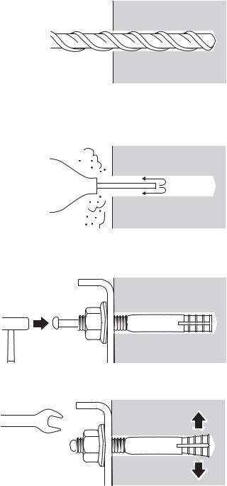
(4) Drill holes of the following diameters and depths.
Drill diameter |
8.5 mm |
|
|
Pilot hole depth |
40mm |
|
|
Anchor hole depth |
35mm |
|
|
(5)Remove the template sheet.
(6)Use a device such as a dust pump to clean out concrete dust from the hole.
(7)Position the wall plate on the wall and insert M8 x 50 mm expansion anchors into the holes. Attach the nut and tap it with a hammer until the core touches the top of the anchor.
(8) Tighten the nut with a spanner to secure the wall plate to the wall.
20
d Determine the projection distance and pull out the slider |
|
||
(1) |
In the projection distance table, check the number for the slider measure (b). |
English |
|
(2) |
Loosen the M4 x 12 mm hexagon socket head cap bolts (x2), and then pull out the slider on |
||
|
|||
|
the setting plate. |
|
|
|
Align the slider with the measure (b+x) that is equal to the slider measure (b) plus the thickness of the |
|
|
|
projection screen (x). |
|
|
|
M4 x 12 mm hexagon socket head cap bolts (x2) |
|
|
Slider measure
e Route the cables through the setting plate
Route the necessary cables through the setting plate.
21
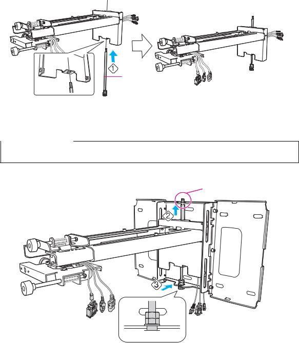
f Attach the setting plate to the wall plate
(1) Insert the hexagonal axis in the setting plate ( ).
).
Hexagonal axis
(2)Insert the hexagonal axis at the top of the setting plate into the wall plate ( ).
).
(3)Insert the M8 hexagon bolt at the bottom of the setting plate into the wall plate ( ).
).

 Caution
Take care not to trap the cables between the setting plate and wall plate.
Hexagonal axis
 M8 hexagon bolt
22
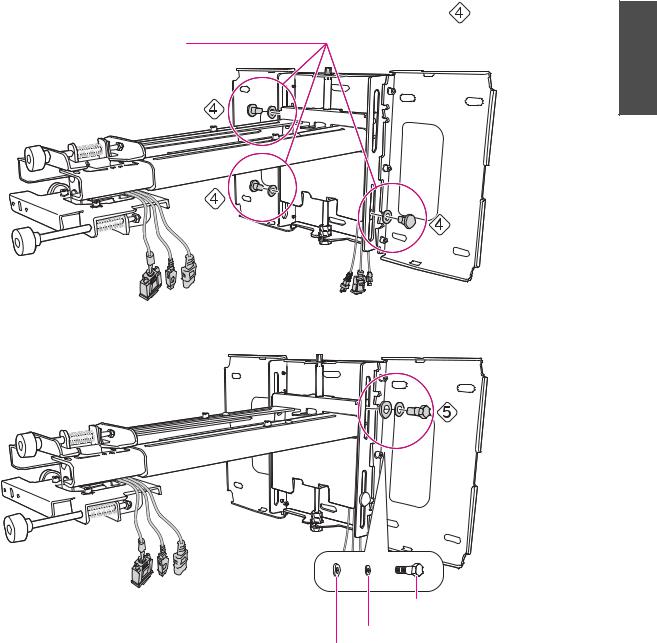
(4) Secure the setting plate to the wall plate by tightening the supplied M6 x 20 mm cross |
|
recessed head shoulder screws (x3) with the No.3 cross-head screwdriver ( |
). |
M6 x 20 mm cross recessed |
English |
|
|
head shoulder screws (x3) |
|
(5) Loosely tighten the M6 x 20 mm hexagon shoulder bolt supplied ( ).
).
M6 x 20 mm hexagon shoulder bolt
Spring washer
Washer
23
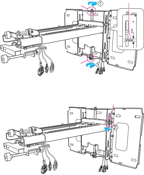
g Adjust the vertical slide to align it with the standard position
(1)Adjust the vertical slide with the M8 hexagon bolt at the bottom of the setting plate, or the hexagonal axis at the top of the setting plate. Align with the standard position ( ).
).
Tightening the M8 hexagon bolt lowers the setting plate, and loosening the bolt raises it. Tightening the hexagonal axis raises the setting plate, and loosening the axis lowers it.
Standard position
Hexagonal axis
M8 hexagon bolt
(2) Tighten the M6 x 20 mm hexagon shoulder bolt to secure the setting plate ( ).
).
M6 x 20 mm hexagon shoulder bolt
24
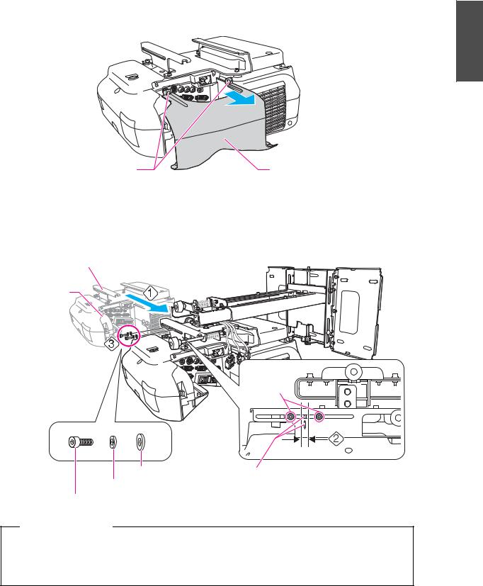
h Secure the projector to the setting plate |
|
(1) Loosen the two screws and remove the cable cover from the projector. |
English |
|
Screws (x2) |
Cable cover |
(2)Insert the slide plate into the setting plate from the interface side of the projector ( ). Align the 3-axis adjustment unit with the slide plate's standard position (
 ).
).
(3)Tighten the M4 x 12 mm hexagon socket head cap bolts (x2) ( ).
).
Slide plate
Projector interface side
Bolt positions |
Washer |
Standard position |
Spring washer
M4 x 12 mm hexagon socket head cap bolts
 Warning
If you use adhesives to prevent the screws from loosening or things such as lubricants or oils on the slide plate fixing part of the projector, the case may crack and cause the projector to fall, resulting in personal injury or property damage. Do not use adhesives, lubricants, or oils to install or adjust the setting plate.
25
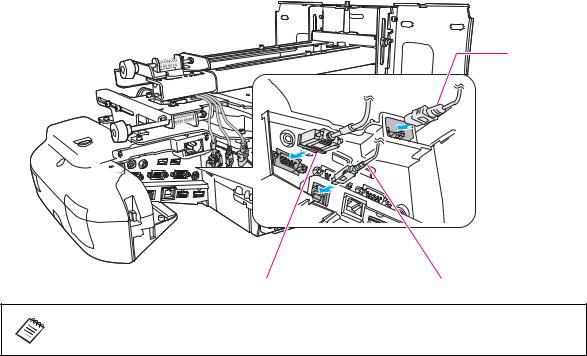
i Connect the power cord and other cables to the projector
Connect any necessary cables such as the power cord, computer cable, and USB cable to the projector.
Power cord
Computer cable |
USB cable |
When using the interactive function, you need a computer cable and a USB cable.
26
6. Adjusting the Projection Screen |
English |
|
To ensure maximum projection screen quality, follow the steps below to adjust the projection screen. |
||
|
||
Do not make adjustments with the Keystone function of the projector. Doing so may |
|
|
result in a reduction in image quality. |
|
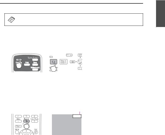
a Turn on the projector
Using the Remote Control |
Using the Control Panel |
||
|
|
|
|
|
|
|
|
|
|
|
|
|
|
|
|
|
|
|
|
|
|
|
|
|
|
|
|
b Change the aspect ratio
Each time you press the [Aspect] button on the remote control, the aspect name is displayed on the screen and the aspect ratio changes.
Change the setting according to the signal for the connected equipment.
Remote Control |
Aspect Ratio |
|
16:9 |
Alternatively, set the aspect ratio in [Signal] - [Aspect] from the Configuration menu. sProjector's User's Guide "Configuration Menu"
27
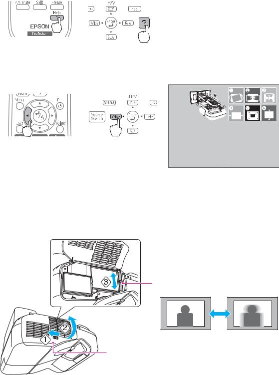
c Display the test pattern
(1) Press the [Help] button.
Using the Remote Control |
Using the Control Panel |
(2)Press the [ ] button on the remote control, or the [Wide] button on the control panel.
The test pattern is displayed.
Using the Remote Control |
Using the Control Panel |
d Adjust the focus
(1)Move the air filter cover lever ( ) to open the air filter cover (
 ).
).
(2)Use the focus lever to adjust the focus ( ).
).
Focus lever
Air filter cover
(3) After you finish making the adjustment, close the air filter cover.
28
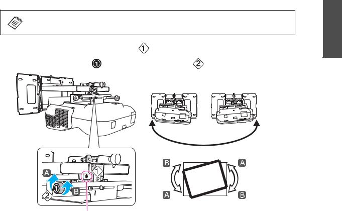
e Use the left adjustment dial to adjust the horizontal roll |
||||
|
Repeat steps eto jas necessary. |
|
English |
|
|
|
|
||
(1) |
Loosen the screw in the following figure ( |
). |
|
|
(2) |
Turn the adjustment dial ( |
) to adjust the horizontal roll ( |
). |
|
Screw
(3)After you finish making all of the adjustments in steps eto j, tighten the screw you loosened in  .
.
29

f Use the right adjustment dial to adjust the horizontal rotation
(1)Loosen the screws (x2) in the following figure ( ).
).
(2)Turn the adjustment dial (  ) to adjust the horizontal rotation (
 ).
).
Screws (x2)
(3)After you finish making all of the adjustments in steps eto j, tighten the screws (x2) you loosened in  .
.
g Use the top adjustment dial to adjust the vertical tilt
(1)Loosen the screw in the following figure ( ).
).
(2)Turn the adjustment dial (  ) to adjust the vertical tilt (
 ).
).
Screw
(3)After you finish making all of the adjustments in steps eto j, tighten the screw you loosened in  .
.
30
 Loading...