Emerson Fisher 3610J, Fisher 3610JP, Fisher 3620J, Fisher 3620JP Data Sheet

3610J and 3620J Positioners |
Product Bulletin |
62.1:3610 |
|
D200064X012 |
February 2015 |
|
|
Fisherr 3610J and 3620J Positioners and 3622
Electro-Pneumatic Converter
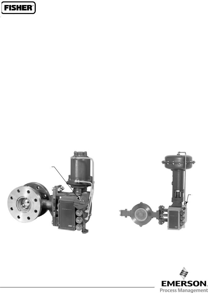
Fisher 3610J or 3610JP pneumatic and 3620J or 3620JP electro-pneumatic positioners are used in combination with either single or double-acting rotary actuators to accurately position control valves used in throttling applications. The positioner mounts integrally to the actuator housing. These rugged positioners provide a valve position proportional to a pneumatic or a DC current input signal.
The 3610J or 3610JP pneumatic positioner in combination with the Fisher 3622 electro-pneumatic converter becomes the 3620J or 3620JP positioner, respectively. This integral electro-pneumatic converter, can be factory installed or installed in the field on existing positioners. The electro-pneumatic converter receives the DC current input signal and
provides a proportional pneumatic output signal through a nozzle/flapper arrangement.
The output signal from the converter becomes the input signal pressure to the pneumatic positioner, eliminating the need for a remote mounted transducer.
The positioner mounts on the actuator as shown below. Figure 1 shows the cam feedback mechanism for a positioner mounted on the actuator. Positioner bleed air continually purges the enclosure containing the feedback lever and the feedback linkages.
To support diagnostic testing of valve/actuator/positioner packages, connectors, piping, and other hardware can be installed between the 3610J or 3620J positioner and the actuator.
ELECTRO-
PNEUMATIC
CONVERTER
BYPASS
VALVE
W3949
W4920-1
FISHER 3620JP ELECTRO-PNEUMATIC POSITIONER |
FISHER 3610J PNEUMATIC POSITIONER WITH |
WITH 1061 ACTUATOR AND V500 VALVE |
1052 ACTUATOR AND ECCENTRIC DISC VALVE |
www.Fisher.com

Product Bulletin |
3610J and 3620J Positioners |
62.1:3610 |
|
February 2015 |
D200064X012 |
|
|
Specifications |
|
Available Configurations
Refer to the following type number description on page 6
Input Signal
3610J or 3610JP:
Standard: J 0.2 to 1.0 bar (3 to 15 psig), J 0.4 to 2.0 bar (6 to 30 psig), or J split range, see table 1. Adjustable: Zero is adjustable from 0.07 to 1.5 bar (1 to 22 psig) for standard valve rotations. Span is adjustable from 0.2 to 2.0 bar (3.2 to 28.8 psi) for
standard valve rotations. Location of adjustments are shown in figure 2.
3620J and 3620JP:
4-20 mA DC constant current with 30 VDC maximum compliance voltage. Minimum terminal voltage is 2.4 VDC at 20 mA. Split range is also available,
see table 1.
Output Signal
Pneumatic pressure as required by the actuator up to full supply pressure
Action(1): Field-reversible between J direct and J reverse within the pneumatic positioner
Equivalent Circuit
3620J and 3620JP: 120 ohms shunted by three 5.6 V zener diodes
Typical Performance
Independent Linearity:
Direct-Acting 3610J and 3620J: ±1.5% of output span Reverse-Acting 3610J and 3620J: ±0.75% of output span Direct-Acting 3610JP and 3620JP: ±1.25% of output span
Reverse-Acting 3610JP and 3620JP: ±0.5% of output span
Hysteresis:
3610J: 1.0% of output span 3620J: 0.75% of output span 3610JP: 0.5% of output span 3620JP: 0.6% of output span
Deadband: 0.1% of input span
Electromagnetic Compliance for 3622 electro-pneumatic converter:
Meets EN 61326-1 (First Edition) ÃImmunity—Industrial locations per Table 2 of ÃÃthe EN 61326-1 standard. Performance is ÃÃshown in table 2 below. ÃEmissions—Class A
ÃÃISM equipment rating: Group 1, Class A
Note:The Electromagnetic Compliance specifications also apply to 3620J positioners
Maximum Supply Air Demand(2)
3610J and 3620J:
1.4bar (20 psig) Supply: 13 normal m3/hour (490 scfh)
2.4bar (35 psig) Supply: 17 normal m3/hour (640 scfh)
3610JP and 3620JP:
5.2 bar (75 psig) Supply: 37 normal m3/hour (1380 scfh)
6.9 bar (100 psig) Supply: 46 normal m3/hour (1700 scfh)
Operating Influences
Supply Pressure Sensitivity: A 10% change in supply pressure changes the valve shaft position less than the following percentages of valve rotation:
3610J and 3620J: 1.0% at 1.4 bar (20 psig) supply pressure
3610JP and 3620JP: 1.5% at 4.1 bar (60 psig) supply pressure
Supply Pressure(3)
Minimum Recommended: 0.3 bar (5 psig) above actuator requirement [1.4 bar (20 psig) for a 0.2 to 1.0 bar (3 to 15 psig) nominal actuator signal; 2.4 bar (35 psig) for a 0.4 to 2.0 bar (6 to 30 psig) nominal actuator signal].
Maximum: 10.3 bar (150 psig) or maximum pressure rating of the actuator, whichever is lower.
Supply Medium: Air or natural gas(4)
3620J and 3620JP are not approved for use with natural gas as the supply medium
- continued -
2

3610J and 3620J Positioners |
Product Bulletin |
62.1:3610 |
|
D200064X012 |
February 2015 |
|
|
Specifications (continued) |
|
|
|
Steady-State Air Consumption(2) |
Other Classifications/Certifications for 3622 |
3610J: 0.40 normal m3/hour (15 scfh) at 1.4 bar (20 psig) supply pressure
3610JP: 0.64 normal m3/hour (24 scfh) at 6.9 bar (100 psig) supply pressure
3620J: 0.49 normal m3/hour (18 scfh) at 1.4 bar (20 psig) supply pressure
3620JP: 0.93 normal m3/hour (35 scfh) at 6.9 bar (100 psig) supply pressure
Operative Temperature Limits(3)
-40 to 82_C (-40 to 180_F)
Electrical Classification for 3622
Hazardous Area:
CSA— Intrinsically Safe, Explosion proof, Type n Dust-Ignition proof, Division 2
FM— Intrinsically Safe, Explosion proof, Type n, Non-incendive, Dust-Ignition proof,
ATEX— Intrinsically Safe, Type n, Flameproof
IECEx— Intrinsically Safe, Type n, Flameproof (Gas Atmospheres Only)
Refer to tables 3, 4, 5, and 6 for additional information.
Note: These classifications also apply to 3620J positioners
Housing Classification for 3622
CSA— Type 3 Encl.
FM— NEMA 3, IP54
ATEX— IP64
IECEx— IP54
Mount instrument with vent on side or bottom if weatherproofing is a concern.
Note: These classifications also apply to 3620J positioners
CUTR— Customs Union Technical Regulations (Russia, Kazakhstan, and Belarus)
INMETRO— National Institute of Metrology, Quality and Technology (Brazil)
KGS— Korea Gas Safety Corporation (South Korea)
Contact your Emerson Process Management sales office for classification/certification specific information
Note: These classifications also apply to 3620J positioners
Hazardous Area Classification for 3610J Positioners
Complies with the requirements of ATEX Group II Category 2 Gas and Dust
Meets Customs Union technical regulation TP TC 012/2011 for Groups II/III Category 2 equipment
II Gb c T*X
III Db c T*X
Note: These ratings do not apply to 3620J positioners
Construction Materials
All Positioners:
Case: Low copper aluminum alloy Cover: Polyester plastic
Feedback Lever: Stainless steel
Range Spring: Zinc-plated steel
Input Module and Relay Diaphragms: Nitrile and polyester
Relay Valve Plugs and Seats: Stainless steel
Tubing: Copper (standard)
Fittings: Brass (standard)
Gauges: Chrome-plated brass connection with plastic case
3620J and 3620JP:
Housing and Cap: Low copper aluminum alloy
Pressure Connections
1/4 NPT internal
- continued -
3

Product Bulletin |
3610J and 3620J Positioners |
62.1:3610 |
|
February 2015 |
D200064X012 |
|
|
Specifications (continued) |
|
|
|
Rotary Valve Rotation
60, 75, or 90 degrees
Characterized Cams
See Characterized Cams section
Electrical Connection for 3620J and 3620JP
1/2-14 NPT Conduit Connection
Options
3610J and 3610JP:
J Supply pressure gauge, J tire valves, or J plugs, J Integral mounted bypass valve on 3610J only
3620J and 3620JP:
J Supply pressure gauge, J tire valves, or J plugs
Approximate Weight
3610J positioners: 2.5 kg (5.6 pounds)
3620J positioners: 3.6 kg (8.0 pounds)
NOTE: Specialized instrument terms are defined in ANSI/ISA Standard 51.1 - Process Instrument Terminology.
1.For direct action, an increasing input signal extends the actuator rod. For reverse action, an increasing input signal retracts the actuator rod.
2.Normal m3/hr--normal cubic meters per hour (0_C and 1.01325 bar absolute). Scfh--standard cubic feet per hour (60_F and 14.7 psia).
3.The pressure and temperature limits in this document and any applicable standard or code limitation should not be exceeded.
4.Natural gas should contain no more than 20 ppm of H2S.
Table 1. Split-Range Capabilities
3610J AND 3610JP POSITIONERS(1)
|
Split |
0.2 to 1.0 Bar (3 to 15 Psig) Input Signal |
|
0.4 to 2.0 Bar (6 to 30 Psig) Input Signal |
|||
|
Bar |
|
Psig |
|
Bar |
Psig |
|
|
|
|
|
||||
Two-way |
|
0.2 to 0.6 |
|
3 to 9 |
|
0.4 to 1.2 |
6 to 18 |
|
0.6 to 1.0 |
|
9 to 15 |
|
1.2 to 2.0 |
18 to 30 |
|
|
|
|
|
||||
|
|
|
|
|
|
|
|
|
|
0.2 to 0.5 |
|
3 to 7 |
|
0.4 to 0.9 |
6 to 14 |
Three-way |
|
0.5 to 0.7 |
|
7 to 11 |
|
0.9 to 1.5 |
14 to 22 |
|
|
0.7 to 1.0 |
|
11 to 15 |
|
1.5 to 2.0 |
22 to 30 |
|
|
|
|
|
|
|
|
|
|
|
3620J AND 3620JP POSITIONERS(1) |
|
|
||
|
Split |
|
|
4-20 Milliampere Input Signal |
|
||
Two-way |
|
|
|
4 to 12 |
|
|
|
|
|
|
12 to 20 |
|
|
||
|
|
|
|
|
|
||
|
|
|
|
|
|
|
|
|
|
|
|
4 to 9.3 |
|
|
|
Three-way |
|
|
|
9.3 to 14.7 |
|
|
|
|
|
|
|
14.7 to 20 |
|
|
|
|
|
|
|
|
|
|
|
1. This table is only valid for the following standard valve rotations/range spring combinations: 90_/18A7845X012 (blue), 75_/18A7846X012 (yellow), and 60_/18A5118X012 (red). Contact your Emerson Process Management sales office or the factory for input signal ranges not listed.
Table 2. Fisher 3622 Electro-Pneumatic Converter(1) EMC Summary Results—Immunity
Port |
Phenomenon |
Basic Standard |
Test Level |
Performance |
|
Criteria(2) |
|
||||
|
|
|
|
|
|
|
Electrostatic Discharge (ESD) |
IEC 61000-4-2 |
4 kV contact; 8 kV air |
A |
|
|
|
|
|
|
|
|
|
|
80 to 1000 MHz @ 10V/m with 1 kHz AM at 80% |
|
|
Enclosure |
Radiated EM field |
IEC 61000-4-3 |
1400 to 2000 MHz @ 3V/m with 1 kHz AM at 80% |
A |
|
|
|
2000 to 2700 MHz @ 1V/m with 1 kHz AM at 80% |
|
|
|
|
|
|
|
|
|
|
|
|
|
|
|
|
Rated power frequency |
IEC 61000-4-8 |
60 A/m at 50 Hz |
A |
|
|
magnetic field |
||||
|
|
|
|
|
|
|
|
|
|
|
|
|
Burst (fast transients) |
IEC 61000-4-4 |
1 kV |
A |
|
|
|
|
|
|
|
I/O signal/control |
Surge |
IEC 61000-4-5 |
1 kV (line to ground only, each) |
B |
|
|
|
|
|
|
|
|
Conducted RF |
IEC 61000-4-6 |
150 kHz to 80 MHz at 3 Vrms |
A |
|
|
|
|
|
|
|
Specification limit = ±1% of span
1. The information contained in the table also applies to 3620J, 3620JP, and 3621JP electro-pneumatic positioners. 2. A=No degradation during testing. B = Temporary degradation during testing, but is self-recovering.
4
 Loading...