Deutz TCD 2013 L04-06 4V Instruction Manual

2.1Engine type
2.2Engine diagrams
2.3Lube oil circuit
2.4Fuel circuit
2.5Coolant circuit
2.6Electrics
Engine description
2
cardiagn.com
© 2005

Engine description |
2.1 Engine type |
2 |
|
2.1.1 Company plate |
2.1.2 Location of company plate |
|
|
|
|
© 35 985 0 |
The engine type A, engine numberB and the power data are stamped on the company plate. The engine type and number must be stated when purchasing spare parts.
© 38 986 0 |
The company plate C is fixed on the crankcase.
© 38 987 0 |
cardiagn.com |
Or company plate C is fixed on the cylinder head |
cover.
Or both plates are attached.
© 2005

2.1 Engine type |
Engine description |
2.1.3 Engine number |
2.1.4 Cylinder numbering |
|
2 |
|
|||
|
|
|
|
© 38 988 |
0 |
The engine number is stamped on the crankcase (arrow) and on the company plate.
© 38989 |
0 |
The cylinders are counted consecutively, starting from the flywheel.
cardiagn.com
© 2005

Engine description |
2.2 Engine diagrams |
2 |
2.2.1 |
Operation side |
|
|
|
TCD2013L044V |
|
|
|
|
|
|
1 |
Cylinder head cover |
|
|
|
2 |
Transportation eyelets |
|
|
|
3 |
Heating flange |
|
|
|
4 |
Cabin heater connection |
|
|
|
5 |
Intake elbow to charge air cooler |
|
|
|
6 |
Connection to air filter |
|
|
|
7 |
Coolant outlet adapter |
|
|
|
8 |
Deflection pulley |
|
|
|
9 |
Belt pulley on crankshaft |
|
|
|
10 |
Tension pulley |
|
|
|
11 |
Oil tray |
|
|
|
12 |
Oil drain screw |
|
|
|
13 |
Coolant inlet adapter |
|
|
|
14 |
Generator |
|
|
|
15 |
Oil cooler |
|
|
|
16 |
Exchangeable lube oil filter |
|
|
|
17 |
Engine control unit |
|
|
|
18 |
Exchangeable fuel filter |
|
|
|
19Railwithpressurereducingvalveandpressure |
|
|
|
|
20 |
sensor |
|
|
|
Crankcase ventilation (open system) |
|
|
|
|
21 |
Oil filler neck |
|
© 2005 |
© 38 980 |
1 |
|
|
|
|
||
cardiagn.com

2.2 Engine diagrams |
Engine description |
2.2.6 |
Starter side |
|
|
TCD2013L044V |
|
|
© 38 981 |
1 |
22Charge air temperature line to transmitter
23Exhaust manifold
24Compressor (optional)
25SAE housing
26Starter cover
27Oil return line from turbocharger
28Inlet combustion air turbocharger
29Turbocharger exhaust gas outlet
30Screening plate (thermal protection)
2
cardiagn.com
© 2005

Engine description |
2.2 Engine diagrams |
2 |
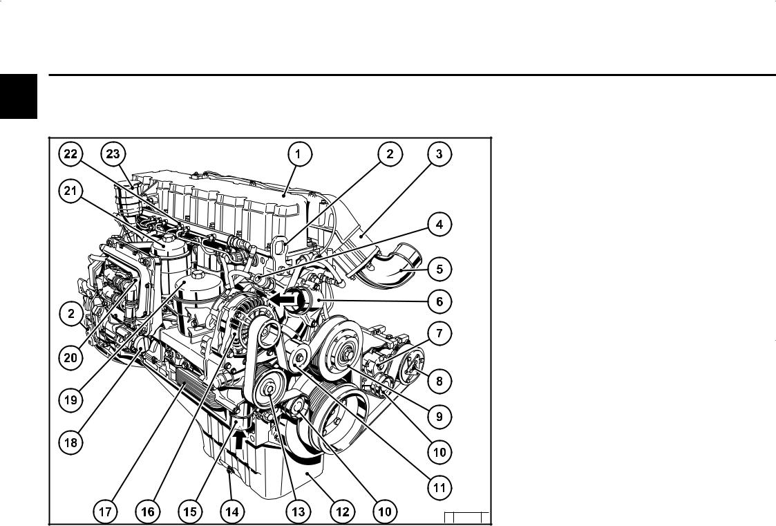
2.2.3 |
Operation side |
|
|
TCD2013L064V |
|
|
|
© 2005 |
© 38 982 |
0 |
|
|
1Cylinder head cover
2Transportation eyelets
3Heating flange
4Cabin heater connection
5Intake elbow from charge air cooler
6Thermostat housing (coolant outlet)
7Spring-loaded tension pulley
8Compressor (optional)
9Belt pulley for fan attachment
10Tension pulley (s)
11Deflection pulley
12Oil tray
13Belt pulley coolant pump
14Oil drain screw
15Coolant inlet adapter
16Generator
17Oil cooler
18Hydraulic pump or compressor installation (optional)
19Exchangeable lube oil filter
20Engine control unit with fuel cooling
21Exchangeable fuel filter
22Railwithpressurereducingvalveandpressure sensor
23 Crankcase ventilation (open system)
cardiagn.com
 Loading...