


D 2011 L03 i
Deutz D 2011 L03 i, D 2011 L02 i, TD 2011 L04 w, D 2011 L04 i, D 2011 L03 o Operation Manual
...
Operation Manual
D/TD/TCD 2011
OBJ_DOKU-15294-001.fm Seite 1 Donnerstag, 28. Februar 2008 9:58 09
Notes
2 © 2008
Notes
z
This engine is defined exclusively for purpose
according to the scope of delivery and built by
the equipment manufacturer (use for the intended purpose). Any other use above and beyond
this will be considered as misuse. The manufacturer will not accept any liability for damages resulting from this. The user bears the sole risk.
z
Use for the intended purpose also includes observance of the operating, maintenance and repair conditions specified by the manufacturer.
The engine should only be operated, serviced
and repaired by personnel trained in its use and
the hazards involved.
The pertinent rules for the prevention of accidents and other generally recognised safety and
industrial medicine rules must be observed.
z
When the engine is running there is a danger of
injury caused by:
– rotating and hot components
– on motors with external ignition (high electri-
cal voltage). Contact must be avoided!
z
Unauthorised engine modifications will invalidate
any liability claims against the manufacturer for
resultant damage.
z
Equally, manipulations to the injection and control system can affect the engine's performance
and the exhaust characteristics. Adherence to
legislation on pollution can no longer be guaranteed under such conditions.
z
Do not change the cooling air feed area to the
blower of fan. An unobstructed cooling air supply
must be guaranteed.
The manufacturer will accept no liability for damage resulting from this.
z
When carrying out maintenance work on the en-
gine, the use of DEUTZ original parts is prescribed. These are specially designed for your
engine and guarantee perfect operation.
Non-compliance results in the expiry of the warranty!
Maintenance/cleaning work on the engine may
only be carried out when the engine is not running and has cooled down.
When doing this, make sure that the electrical
system is switched off (remove ignition key).
The specifications for accident prevention with
electrical systems (e.g. VDE-0100/-0101/-0104/0105 Electrical protective measures against dangerous contact voltages) must be observed.
Cover all electrical components tightly when
cleaning with liquids.
z
Do not work on the fuel system while the engine
is running -
Danger to life!
Wait for the pressure to drop after the engine has
come to a standstill (in engines with DEUTZ
Common Rail about 5 minutes, otherwise
1 minute) because the system is under high
pressure
- Danger to life!
During the first trial run do not stand in the danger area of the engine.
Danger due to high pressure in case of leaks -
Danger to life!
– In case of leaks immediately contact work-
shop.
– When working on the fuel system, make sure
that the engine is not started inadvertently
during repairs -
Danger to life!
OBJ_DOKU-15294-001.fm Seite 2 Donnerstag, 28. Februar 2008 9:58 09
Foreword
© 2008 3
Dear customer,
Congratulations on the purchase of your DEUTZ engine.
DEUTZ air/liquid-cooled engines are developed for a
broad spectrum of applications. Consequently, a
wide range of variants is offered to meet the requirements of specific cases.
The engine is equipped accordingly for the particular
installation situation, i.e. not all the components described in the operating manual are installed in your
engine.
We have endeavoured to highlight any differences
so that you will be able to locate the operating and
maintenance instructions applicable to your engine
more quickly and easily.
Please make sure that this operating manual is available to everyone involved in the operation, maintenance and repair of the engine and that they have
understood the contents.
If you have any queries, please contact us, we'll be
happy to advise you.
Sincerely,
DEUTZ AG
Engine serial number
Please enter the engine serial number here. This will
simplify the handling of customer service, repair and
spare parts queries.
Notes
We reserve the right to make technical changes to
the descriptions and data in this operating manual in
the interest of further development of the engines.
This document may only be reprinted and reproduced, even in part, with our express permission.
OBJ_DOKU-15294-001.fm Seite 3 Donnerstag, 28. Februar 2008 9:58 09
Contents
4 © 2008
Notes . . . . . . . . . . . . . . . . . . . . . . . 2
Foreword. . . . . . . . . . . . . . . . . . . . . 3
1 General. . . . . . . . . . . . . . . . . . . . 5
2 Engine description . . . . . . . . . . . . . 7
Type . . . . . . . . . . . . . . . . . . . . . 7
Engine illustrations . . . . . . . . . . . . . . 9
Lubricating oil schematic . . . . . . . . . . . 13
Fuel schematic . . . . . . . . . . . . . . . . 18
Coolant schematic . . . . . . . . . . . . . . 19
Exhaust gas recirculation . . . . . . . . . . . 21
Electrics/Electronics . . . . . . . . . . . . . 23
3 Operation . . . . . . . . . . . . . . . . . . 24
Ambient conditions . . . . . . . . . . . . . . 24
Initial commissioning . . . . . . . . . . . . . 25
Start procedure . . . . . . . . . . . . . . . . 27
Operation monitoring . . . . . . . . . . . . . 28
Stop procedure . . . . . . . . . . . . . . . . 30
4 Operating media. . . . . . . . . . . . . . . 31
Lubricating oil . . . . . . . . . . . . . . . . . 31
Fuel . . . . . . . . . . . . . . . . . . . . . . 33
Coolant . . . . . . . . . . . . . . . . . . . . 34
5 Maintenance . . . . . . . . . . . . . . . . . 35
Maintenance schedule . . . . . . . . . . . . 35
6 Care and maintenance work . . . . . . . . 38
Lubricating oil system. . . . . . . . . . . . . 38
Fuel system. . . . . . . . . . . . . . . . . . 40
Cooling system . . . . . . . . . . . . . . . . 44
Engine cleaning. . . . . . . . . . . . . . . . 46
Suction system . . . . . . . . . . . . . . . . 47
Belt drives . . . . . . . . . . . . . . . . . . 49
Setting work . . . . . . . . . . . . . . . . . 51
Electrical system . . . . . . . . . . . . . . . 53
7 Faults. . . . . . . . . . . . . . . . . . . . . 55
Fault table . . . . . . . . . . . . . . . . . . 55
Engine management . . . . . . . . . . . . . 60
8 Transport and storage . . . . . . . . . . . 62
Transport . . . . . . . . . . . . . . . . . . . 62
Protecting the engine against corrosion . . . 63
9 Technical data . . . . . . . . . . . . . . . . 65
Engine and setting data . . . . . . . . . . . 65
Tools . . . . . . . . . . . . . . . . . . . . . 70
OBJ_DOKU-15294-001.fm Seite 4 Donnerstag, 28. Februar 2008 9:58 09
General
© 2008 5
1
DEUTZ diesel engines
DEUTZ diesel engines are the product of years of research and development. Profound know-how combined with high quality requirements are the
guarantee for the production of engines with a long
life, high reliability levels and low fuel consumption.
Obviously the high requirements for the protection of
the environment are also met.
Safety precautions when the engine is running
Maintenance work or repairs may only be performed
on the shut-down engine. Make sure that the engine
cannot be started inadvertently -
Danger of acci-
dent!
After repair work: Check that all guards have been
replaced and that all tools have been removed from
the engine.
Observe industrial safety regulations when running
the engine in an enclosed space or underground.
When working on the running engine, work clothing
must be close fitting.
Never fill the fuel tank while the engine is running.
Service and Maintenance
Service and maintenance are also decisive for
whether the engine satisfactorily meets the set demands. Recommended service intervals must therefore be observed and service and maintenance work
must be carried out conscientiously.
Special care should be taken under abnormally demanding operating conditions.
Original DEUTZ parts
Original DEUTZ parts are subject to the same strict
quality demands as the DEUTZ engines. Further de-
velopments for improving the engines are also introduced in the original DEUTZ parts of course. Only
the use of original DEUTZ parts manufactured according to the state-of-the-art can guarantee perfect
functioning and high reliability.
DEUTZ Xchange components
DEUTZ replacement parts are a low-cost alternative.
Of course, the quality standards here are just as high
as for new parts. DEUTZ replacement parts are
equal to the original DEUTZ parts in function and reliability.
Asbestos
The gaskets used in this engine contain no asbestos.
Please use the appropriate original DEUTZ parts for
maintenance and repair work.
Service
We want to preserve the high performance of our engines, and with it the confidence and satisfaction of
our customers. We are therefore represented worldwide by a network of service branches.
The DEUTZ name does not merely stand for engines
that are the products of extensive development
work, DEUTZ also stands for complete service packages that ensure optimum operation of our engines,
and for customer services operations that you can
count on.
Please contact your DEUTZ-partner in case of malfunctions and sare parts inquiries. Our specially
trained personnel will ensure fast, professional repairs using original DEUTZ spare parts in case of
damage.
The DEUTZ home page gives you a continuously upto-date overview of the service partners in your vicin-
ity with notes on product responsibilities and services. Or you can use another fast, convenient way via
the Internet under www.deutzshop.de. The DEUTZ
P@rts Online parts catalogue gives you a direct contact to your nearest local service partner.
Masthead
DEUTZ AG
Ottostraße 1
51149 Köln
Germany
Phone: +49 (0) 221-822-0
Fax: +49 (0) 221-822-5850
www.deutz.com
E-Mail: info@deutz.com
California
Proposition 65 Warning
Diesel engines and some of its constituents are
known to the State of California to cause cancer,
birth defects and other reproductive harm.
OBJ_DOKU-15294-001.fm Seite 5 Donnerstag, 28. Februar 2008 9:58 09
General
6 © 2008
1
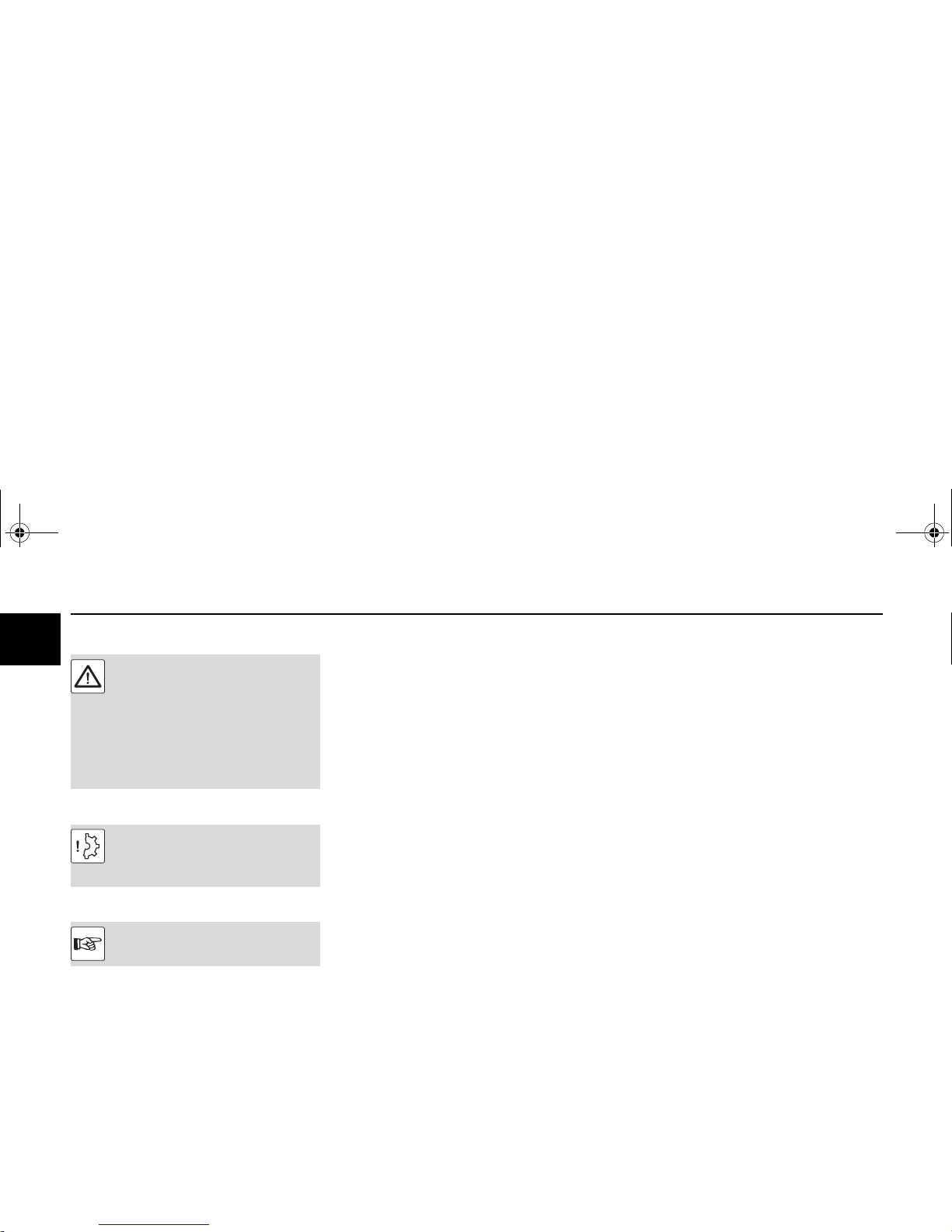
Danger
Caution
Notes
This symbol is used for all safety instructions which, if not observed, present a direct danger to life and limb for the person
involved. Observe these carefully. The attention of operating personnel should be
drawn to these safety instructions. Furthermore, the legislation for "general regulations for safety and the prevention of
accidents" must be observed.
This symbol indicates a danger to the part
and engine. The relevant instructions must
be observed, failure to do so can lead to destruction of the part and the engine.
This symbol accompanies notes of a general kind.
OBJ_DOKU-15294-001.fm Seite 6 Donnerstag, 28. Februar 2008 9:58 09
Type Engine description
© 2008 7
2
Engine type designation
This manual covers the following engine types
D 2011 L02 i D 2011 L02 o D 2011 L04 w
D 2011 L03 i D 2011 L03 o TD 2011 L04 w
D 2011 L04 i D 2011 L04 o TCD 2011 L04 w
TD 2011 L04 i TD 2011 L04 o
TCD
T Exhaust gas turbocharger
C Charge air cooler
DDiesel
2011
2011 Series
L02/L03/L04
L in series
02 No. of cylinders
03 No. of cylinders
04 No. of cylinders
i/o/w
i oil-cooled (integrated cooler)
o oil-cooled
w water-cooled
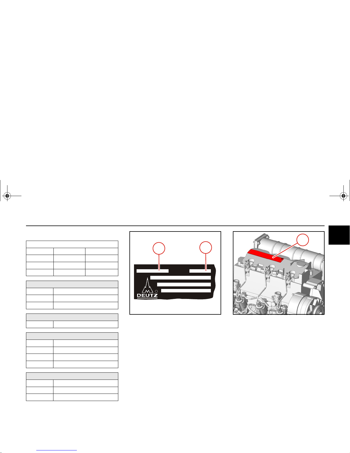
Rating plate
The type (A), engine number (B) and performance
data are stamped on the rating plate.
The engine type and number must be stated when
purchasing spare parts.
DEUTZ AG
DEUTZ AG
MADE IN GERMANY
MADE IN GERMANY
Mot.-Typ
Mot.-Nr.
R
B
A
Location of the rating plate
The rating plate (C) is fixed to the cylinder head cover or the crankcase.
C
OBJ_DOKU-15294-001.fm Seite 7 Donnerstag, 28. Februar 2008 9:58 09
Engine description Type
8 © 2008
2
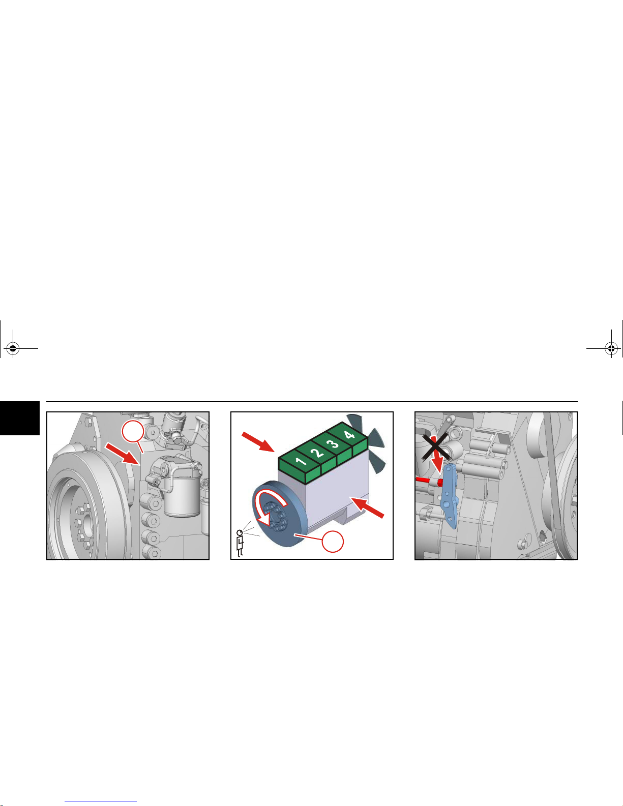
Engine serial number
The engine number (D) is stamped onto the crankcase (arrow) and onto the rating plate.
XXXXXXX
D
Cylinder numbering
Cylinder arrangement
The cylinders are counted consecutively starting
from flywheel (1).
Direction of rotation
Looking onto the flywheel.
rotating to the left: counter-clockwise.
Engine sides
Looking onto the flywheel.
1
left
right
Volume blocking
Unauthorised settings on the regulator will exclude
the manufacturer from all liability for resulting damage. The blocking screws are adequately protected
against this:
z
With locking varnish in version: torque adjustment
z
With protective plastic capsule in version: without torque adjustment.
OBJ_DOKU-15294-001.fm Seite 8 Donnerstag, 28. Februar 2008 9:58 09
Engine illustrations Engine description
© 2008 9
2
?
?
?
?
?
?
1
2
3
4
5
6
16
15
17
18
14
13
12
11
10
9
8
7
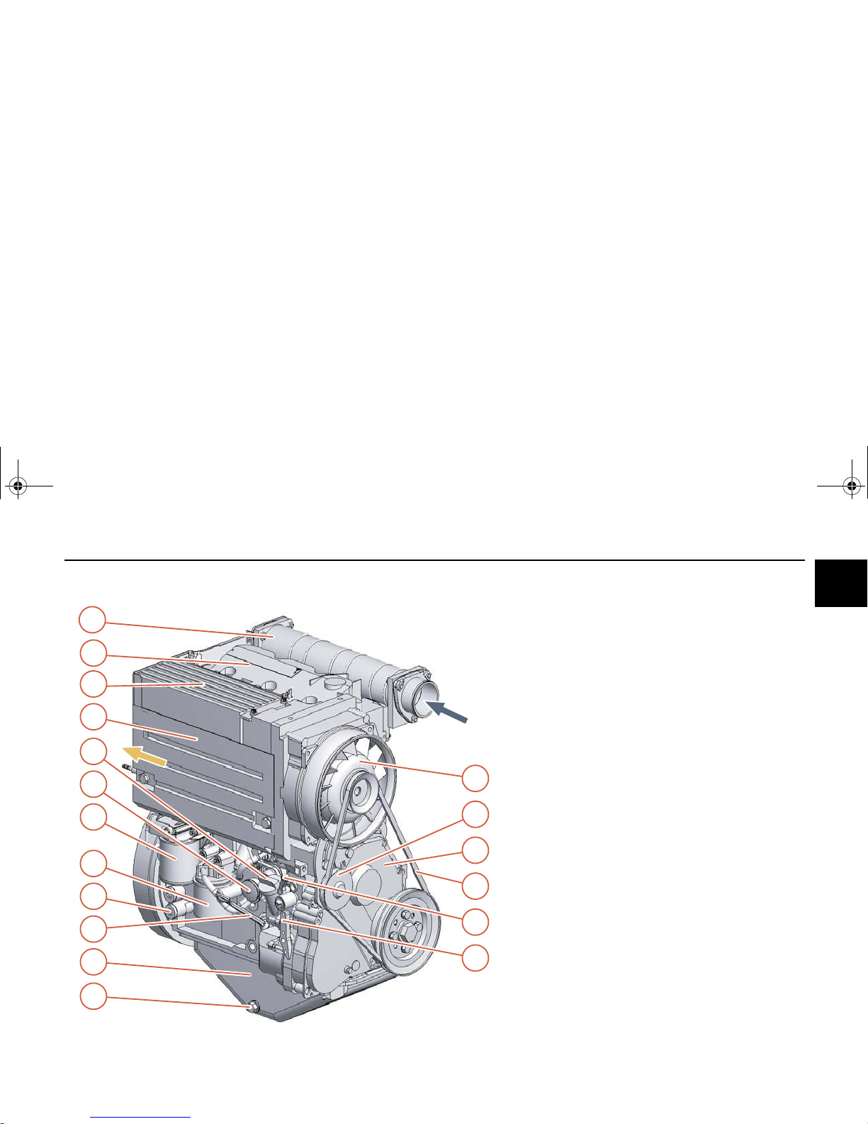
D 2011 L03 i
View from right (example)
1 Cooling fan (with integrated generator)
2 Tension pulley
3 Toothed belt cover
4 V-belt (fan)
5 Stop lever
6 Speed adjusting lever
7 Lubricating oil drain plug
8 Lubricating oil sump
9 Lubricating oil dipstick
10 Connection possibility for cab heating
11 Exchangeable fuel filter
12 Lube oil replacement filter
13 Fuel supply pump with integrated screen filter
14 Lubricating oil filling
15 Removable air guidance cowling (access to fuel
injectors)
16 Lube oil cooler
17 Cylinder head cover
18 Air intake pipe
OBJ_DOKU-15294-001.fm Seite 9 Donnerstag, 28. Februar 2008 9:58 09
Engine description Engine illustrations
10 © 2008
2
1
2
5
4
3
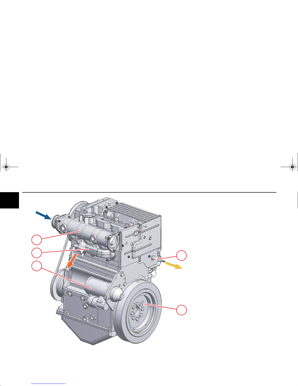
D 2011 L03 i
View from left (example)
1 Fuel return to fuel tank
2 Flywheel
3Starter
4 Exhaust manifold line
5 Air intake pipe
OBJ_DOKU-15294-001.fm Seite 10 Donnerstag, 28. Februar 2008 9:58 09
Engine illustrations Engine description
© 2008 11
2
2
1
3
4
20
19
21
18
17
16
15
14
13
12
11
10
7
8
6
5
9
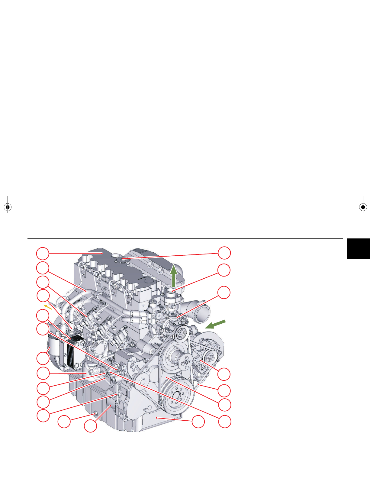
TCD 2011 L04 w
View from right (example)
1 Crankcase breather
2 Coolant outlet to the cooler
3 Coolant pump
4 Generator
5 V-belts
6 Toothed belt cover
7 Lubricating oil filling
8 Lubricating oil sump
9 Lubricating oil pump
10 Lubricating oil drain plug
11 Speed adjusting lever
12 Lubricating oil dipstick
13 Fuel supply pump with integrated screen filter
14 Exchangeable fuel filter
15 Lube oil replacement filter
16 Stop lever
17 Lube oil cooler
18 Coolant inlet
19 Injection pump
20 Coolant return to thermostat
21 Cylinder head cover
OBJ_DOKU-15294-001.fm Seite 11 Donnerstag, 28. Februar 2008 9:58 09
Engine description Engine illustrations
12 © 2008
2
6
7
8
5
4
3
1
2
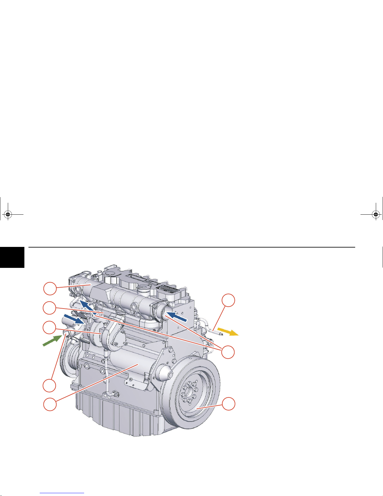
TCD 2011 L04 w
View from left (example)
1 Fuel return to fuel tank
2 Connections charge air cooler
3 Flywheel
4Starter
5 Coolant inlet
6 Turbocharger
7 Exhaust manifold line
8 Charge air line
OBJ_DOKU-15294-001.fm Seite 12 Donnerstag, 28. Februar 2008 9:58 09
Lubricating oil schematic Engine description
© 2008 13
2
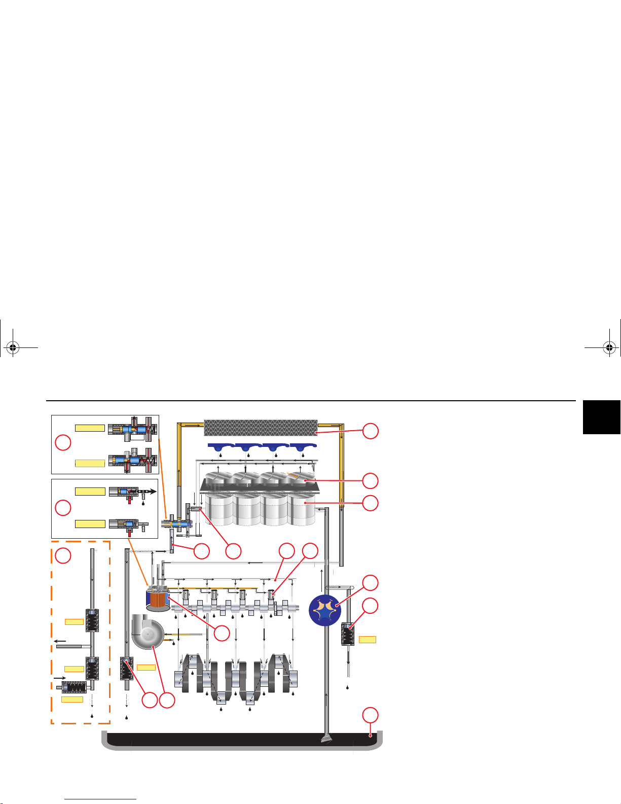
3bar
7bar
T
oil
< 63°C
T
oil
>
63°C
T
oil
<
95°C
T
oil
> 95°C
1,7 bar
1bar
0,3 bar
9
8
15
12
13
14
10
1
3
2
16
11
6
7
4
5
TD 2011 L04 i
(example)
1 Lubricating oil sump
2 Lubricating oil pump
3 Pressure limiting valve
4 Cylinder (lubricating oil-cooled)
The lubricating oil is used first to cool the engine.
5 Cylinder head
6 Lubricating oil return from the cylinders
7 Lubricating oil collection pipe to the thermostat
8 Thermostat
(engine cold) lubricating oil flow directly to the lu-
bricating oil filter
(engine warm) lubricating oil flow through the lu-
bricating oil cooler
9 Lube oil cooler
10 Lubricating oil filter
11 Main lube oil channel
12 Turbocharger
13 Pressure holding valve
14 Connection possibility for cab heating
The standard pressure holding valve must be re-
placed by a combination for this. Retrofitting only
by authorised qualified personnel.
15 Lubricating oil filter console with integrated
switching valve for controlling the hydraulic tap-
pet. When the engine is cold, lubricating
oil is fed to the hydraulic tappet.
To achieve early adjustment of the fuel injection
in a cold start, the hydraulic tappets under the
fuel injectors are supplied with lubricating oil.
16 Hydraulic tappets
OBJ_DOKU-15294-001.fm Seite 13 Donnerstag, 28. Februar 2008 9:58 09
Engine description Lubricating oil schematic
14 © 2008
2
Pö 12/2004
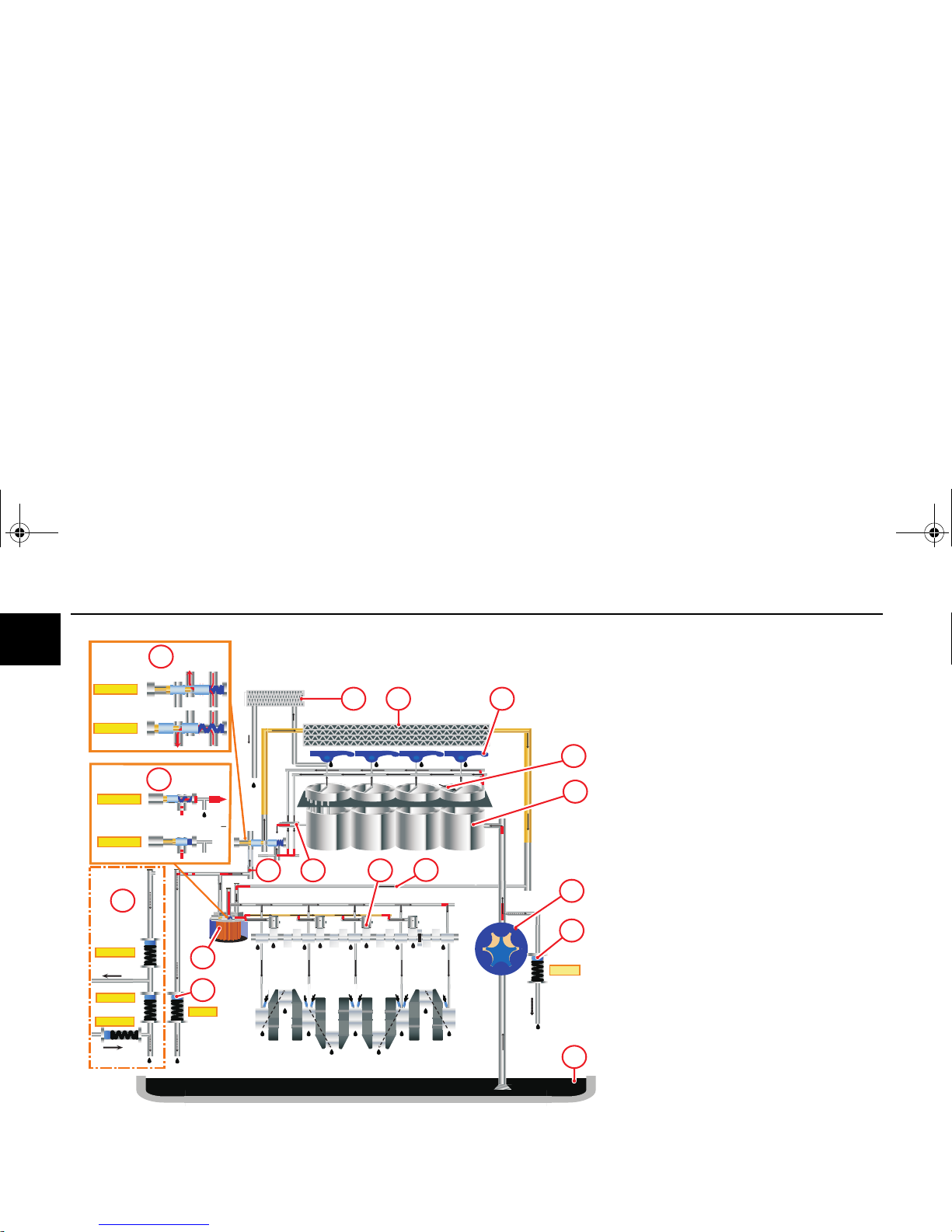
3bar
1,7 bar
1bar
0,3 bar
bar
T
oil
<63°C
T
oil
>63°C
T
oil
<95°C
T
oil
> 95°C
7
1
15
11
8
5
4
12
14
9
6
10
16
2
3
7
17
13
D 2011 L04 i
Exhaust gas recirculation
(example)
1 Lubricating oil sump
2 Lubricating oil pump
3 Pressure limiting valve
4 Cylinder (lubricating oil-cooled)
The lubricating oil is used first to cool the engine.
5 Cylinder head
6 Cooling valve housing (exhaust gas recircula-
tion)
7 Lubricating oil return from the cylinders
8 Rocker arm
9 Lubricating oil collection pipe to the thermostat
10 Thermostat
(engine cold) lubricating oil flow directly to the lu-
bricating oil filter
(engine warm) lubricating oil flow through the lu-
bricating oil cooler
11 Lube oil cooler
12 Lubricating oil filter
13 Main lube oil channel
14 Pressure holding valve
15 Connection possibility for cab heating
The standard pressure holding valve must be re-
placed by a combination for this. Retrofitting only
by authorised qualified personnel.
16 Lubricating oil filter console with integrated
switching valve for controlling the hydraulic tap-
pet. When the engine is cold, lubricating
oil is fed to the hydraulic tappet.
To achieve early adjustment of the fuel injection
in a cold start, the hydraulic tappets under the
fuel injectors are supplied with lubricating oil.
OBJ_DOKU-15294-001.fm Seite 14 Donnerstag, 28. Februar 2008 9:58 09
Lubricating oil schematic Engine description
© 2008 15
2
17 Hydraulic tappets
OBJ_DOKU-15294-001.fm Seite 15 Donnerstag, 28. Februar 2008 9:58 09
Engine description Lubricating oil schematic
16 © 2008
2
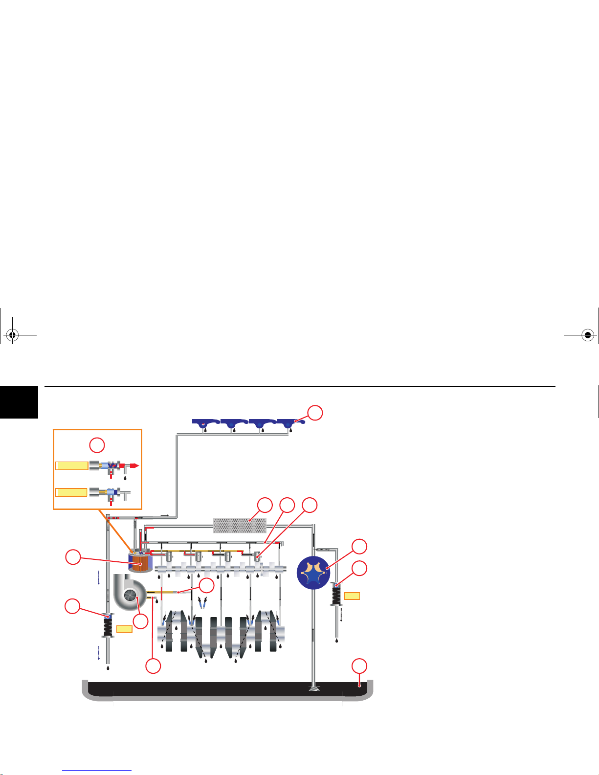
3bar
T
oil
>63°C
T
oil
<63°C
7bar
10
12
4
6
13
1
9
8
5
11
7
3
2
TD 2011 L04 w
(example)
1 Lubricating oil sump
2 Lubricating oil pump
3 Pressure limiting valve
4 Lube oil cooler
5 Lubricating oil filter
6 Main lube oil channel
7 Lubricating oil pipe to the turbocharger
8 Turbocharger
9 Lubricating oil return line from the exhaust turbo-
charger
10 Rocker arm
11 Pressure holding valve
12 Lubricating oil filter console with integrated
switching valve for controlling the hydraulic tap-
pet. When the engine is cold, lubricating
oil is fed to the hydraulic tappet.
To achieve early adjustment of the fuel injection
in a cold start, the hydraulic tappets under the
fuel injectors are supplied with lubricating oil.
13 Hydraulic tappets
OBJ_DOKU-15294-001.fm Seite 16 Donnerstag, 28. Februar 2008 9:58 09
Lubricating oil schematic Engine description
© 2008 17
2
3bar
7bar
Toil
>63°C
Toil
<63°C
4
6
11
8
10
1
5
9
3
2
7
D 2011 w
Exhaust gas recirculation
(example)
1 Lubricating oil sump
2 Lubricating oil pump
3 Pressure limiting valve
4 Lube oil cooler
5 Lubricating oil filter
6 Cooling valve housing (exhaust gas recircula-
tion)
7 Main lube oil channel
8 Rocker arm
9 Pressure holding valve
10 Lubricating oil filter console with integrated
switching valve for controlling the hydraulic tap-
pet. When the engine is cold, lubricating
oil is fed to the hydraulic tappet.
To achieve early adjustment of the fuel injection
in a cold start, the hydraulic tappets under the
fuel injectors are supplied with lubricating oil.
11 Hydraulic tappets
OBJ_DOKU-15294-001.fm Seite 17 Donnerstag, 28. Februar 2008 9:58 09
Engine description Fuel schematic
18 © 2008
2
1
2
5
7
8
9
11
10
6
34
12
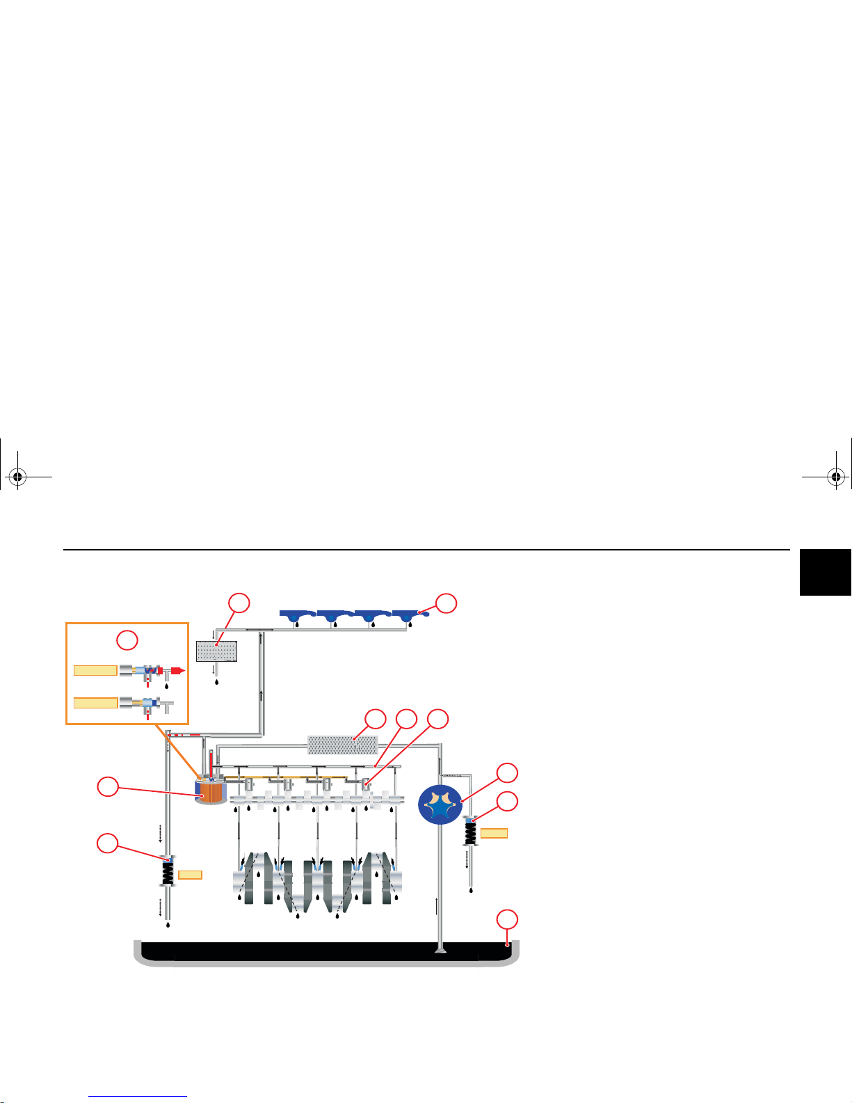
Fuel schematic (example)
1 Fuel line from tank to fuel pump
2 Fuel supply pump with integrated screen filter
3 Fuel pipe from the supply pump to the fuel
change filter
4 Exchangeable fuel filter
5 Fuel pipe from the filter to the fuel injector
6 Fuel pipe to fuel injector
7 Injection pump
8 Injection line to injection valve
9 Injection valve
10 Return collection pipe
11 Fuel return to fuel tank
12 Lubricating oil filter console with integrated
switching valve for controlling the hydraulic tap-
pet. When the engine is cold, lubricating
oil is fed to the hydraulic tappet.
To achieve early adjustment of the fuel injection
in a cold start, the hydraulic tappets under the
fuel injectors are supplied with lubricating oil.
OBJ_DOKU-15294-001.fm Seite 18 Donnerstag, 28. Februar 2008 9:58 09
Coolant schematic Engine description
© 2008 19
2
1
7
10
6
4
3
9
8
5
2
OBJ_DOKU-15294-001.fm Seite 19 Donnerstag, 28. Februar 2008 9:58 09
Engine description Coolant schematic
20 © 2008
2
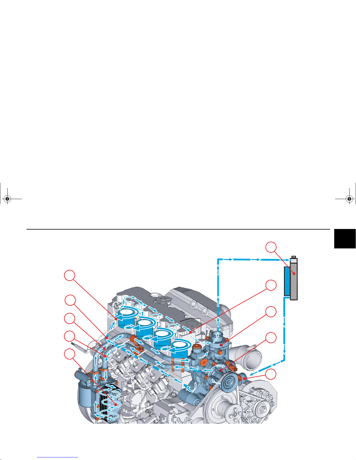
Coolant schematic (example)
D/TD/TCD 2011
w
1 Cooler
2 Coolant inlet
3 Coolant pump
4 Coolant supply for engine cooling
5 Cylinder pipe/head cooling
6 Coolant return to thermostat
7 Thermostat
(engine cold) coolant directly for engine cooling
(engine warm) coolant flow through the cooler
8 Coolant partial flow to the lubricating oil cooler
9 Lube oil cooler
10 Coolant return to thermostat
OBJ_DOKU-15294-001.fm Seite 20 Donnerstag, 28. Februar 2008 9:58 09
Exhaust gas recirculation Engine description
© 2008 21
2
3
2
4
7
8
6
3
5
1
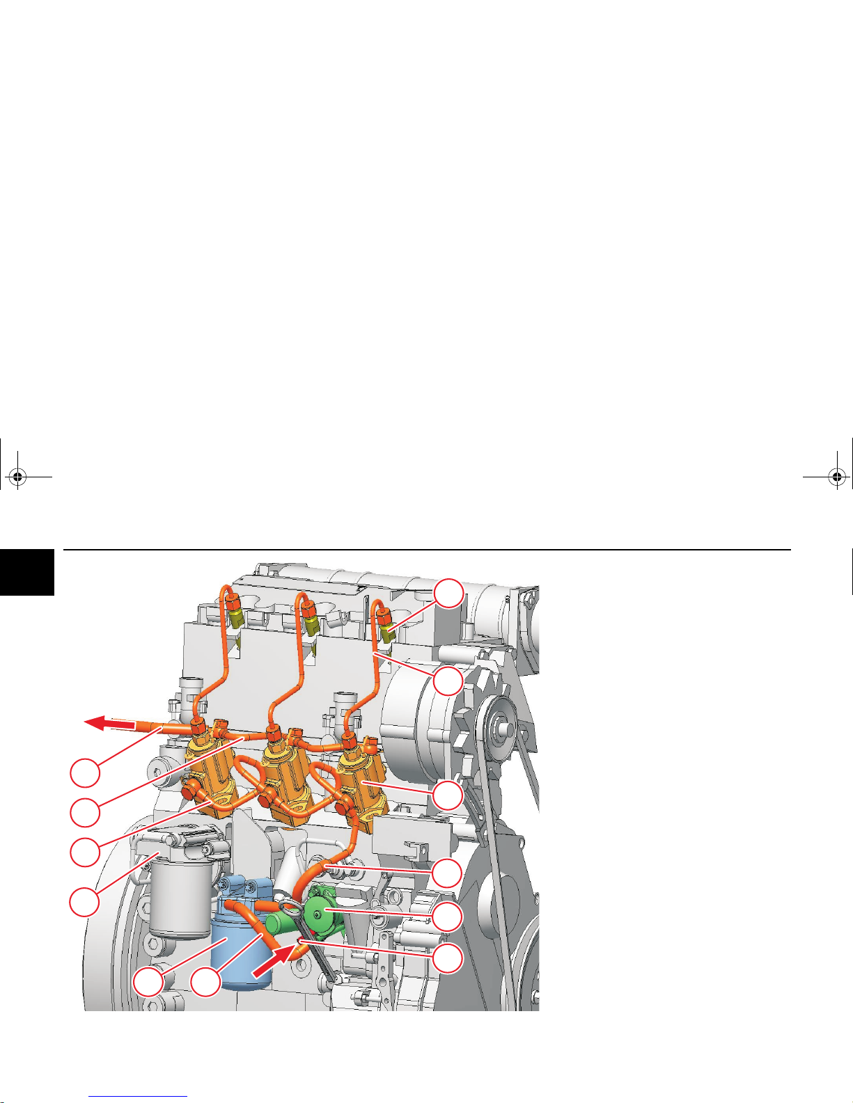
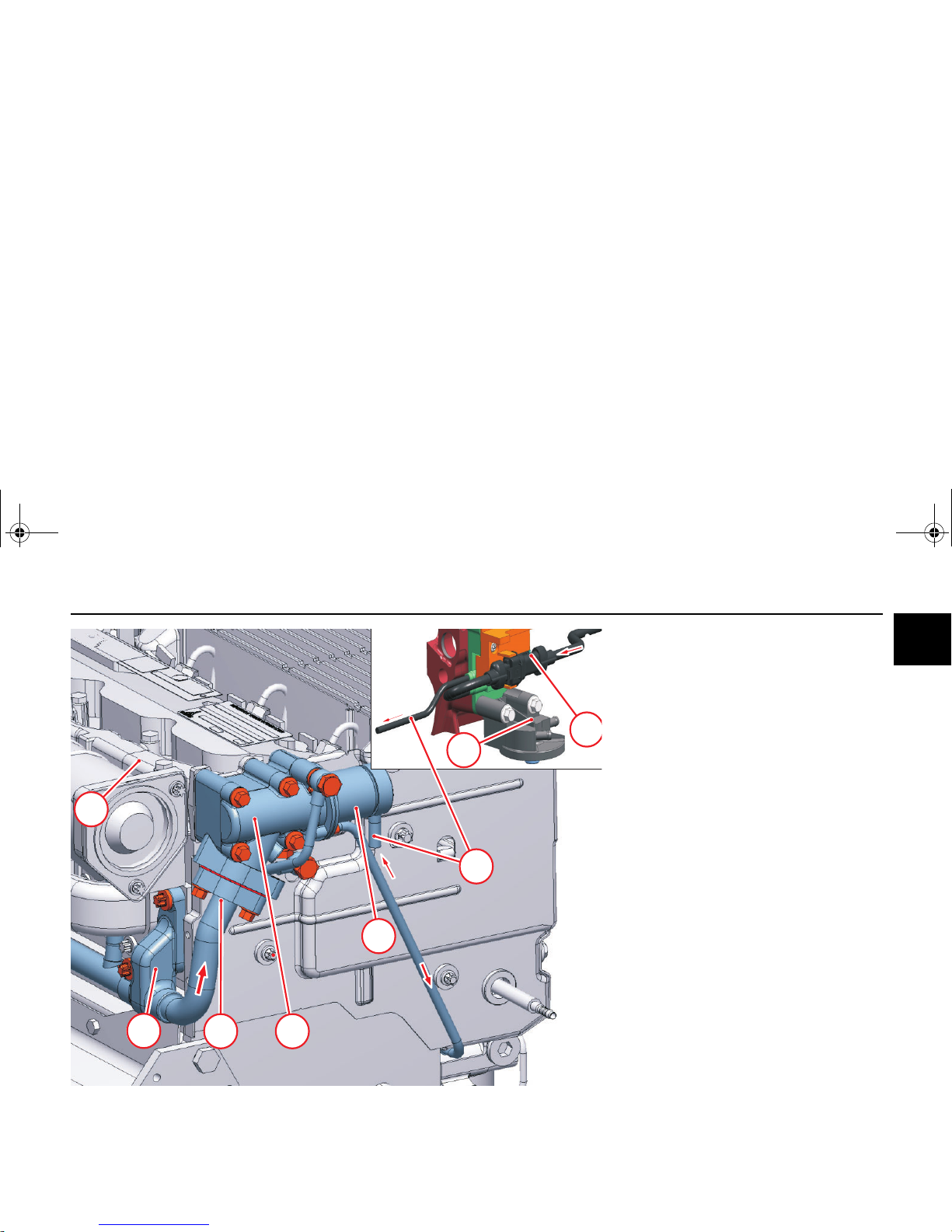
External exhaust gas recirculation
D 2011 L04 i D 2011 L04 o D 2011 L04 w
(example)
1 Exhaust gas partial flow
(not connected)
2 Exhaust gas partial flow
(connected)
3 Valve housing
4 Actuator
(electrically actuated)
5 Distributor pipe
6 Electrical connection
7Switch
The switch is connected internally with the con-
trol linkage. The voltage to the actuator is inter-
rupted at load peaks.
8 Fuel filter console
The switch housing is designed to be safe from manipulation.
Only have work performed on the components by
authorised qualified personnel.
OBJ_DOKU-15294-001.fm Seite 21 Donnerstag, 28. Februar 2008 9:58 09
Engine description Exhaust gas recirculation
22 © 2008
2
[
m
m
]
[°]
1
1
2
3
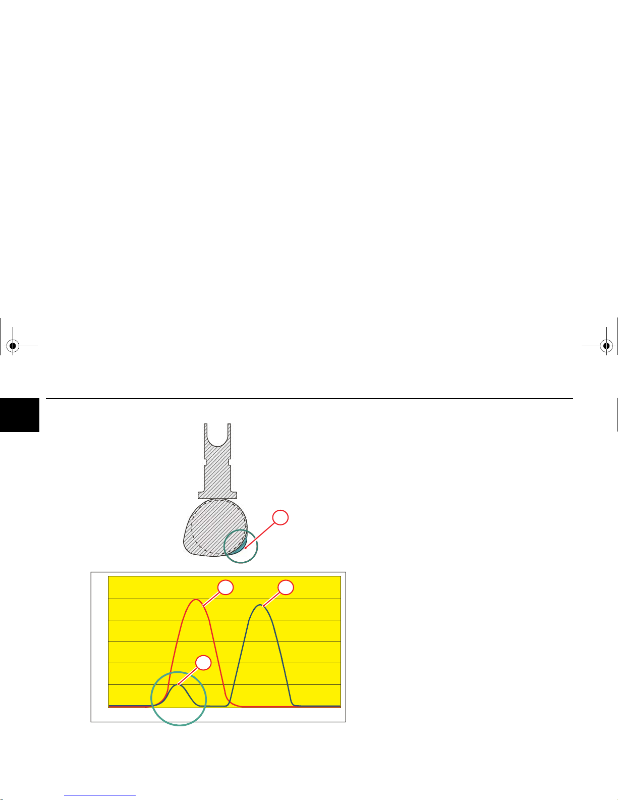
Internal exhaust gas recirculation
Engines with turbocharger
TD/TCD 2011
1 Additional cams for exhaust gas recirculation
Inlet valve opens briefly during the outlet cycle
and emits an exhaust gas partial flow to the suc-
tion system.
This partial volume is sucked back in in the next
suction cycle.
2Outlet valve
3 Inlet valve
OBJ_DOKU-15294-001.fm Seite 22 Donnerstag, 28. Februar 2008 9:58 09
Electrics/Electronics Engine description
© 2008 23
2
Information about the engine electronics
This engine can be equipped optionally with an electronic DEUTZ control unit.
The equipping of the respective system depends on
the desired scope of function and the planned type of
engine application.
The resultant wiring with pin assignment can be seen
in the appropriate wiring diagram.
The installation regulations of the DEUTZ AG must
also be taken into account.
Precautions
The connections of the control units are
only dust and water proof when the mating
plugs are plugged (protection class IP69K)!
The control units must be protected against
spray water and moisture until plugging in
the mating plugs!
Reverse polarity can lead to failure of the
control unit.
To avoid damaging the control units, all the
connections on the control unit must be disconnected before electric welding work.
Interventions in the electrical system contrary to the DEUTZ regulations or by unqualified personnel can permamently
damage the engine electronics and have
serious consequences which are not covered by the manufacturer's guarantee.
Installation instructions
The control units are calibrated to the respective engine and identified by the engine number. Every engine may only be operated with the appropriate
control unit.
Setpoint transmitters (pedal value transmitters) necessary for vehicle operation must be connected to
the vehicle side cable harness and calibrated with
the DEUTZ diagnostic program SERDIA (SERvice
DIAgnosis). Wiring and cable assignment of the vehicle side cable harness must be taken from the connection diagram of the DEUTZ installation
consulting.
It is strictly prohibited:
a) to make changes or connections to the
wiring of the electrical control devices and
the data transmission cable (CAN lines).
b) to switch control units.
Diagnostic and maintenance work may
only be carried out by authorised personnel
using equipment approved by DEUTZ.
Supply voltage
DEUTZ diesel engines must be operated with a 12 V
or 24 V supply. An adequate charging condition of
the battery must be ensured. Interruption of the power supply when the engine is running can lead to
damage to the electrics/electronics. Failure of the
supply voltage leads to engine standstill.
Voltages above 32 Volt will destroy the control unit.
Diagnostics
DEUTZ control units are equipped with self-diagnosis. Active and passive error entries are saved in the
error memory. Active errors are displayed by error
lamp/diagnostic lamp (
60). The active errors can
be called by blink codes or by the DEUTZ diagnostic
program SERDIA. Passive errors must be deleted by
SERDIA.
z
with error lamp (optional).
z
via diagnostic socket (SERDIA).
OBJ_DOKU-15294-001.fm Seite 23 Donnerstag, 28. Februar 2008 9:58 09
 Loading...