


System description Electronic monitoring system
EMS 2

EMS 2
1 Foreword
This system description provides an overview of the design and the operation of the electronic monitoring system (EMS 2).
In addition, the functions which the EMS 2 contains, and the manner in which problems in the engine and in the EMS 2 can be detected, are explained.
© 0702 |
Page 55 |

EMS 2
Page 56 |
© 0702 |
EMS 2
Important notes
2 Important notes
In the event of critical conditions, the EMS 2 may independently shut the engine off, either with or without prior warning depending on the configuration, or may merely provide a warning. The user must be informed of this and must be familiarised with limp-home mode.
! The following states can be recognised with the diagnostic lamp
Display |
State |
Indicates |
|
|
|
Diagnostic lamp |
Lamp test |
System is ready for operation. |
illuminates for 2 s |
|
|
from ignition on. |
|
|
|
|
|
Diagnostic lamp |
Warning |
A reduction in power is only possible in combination with |
continuously |
regarding exceeded limit |
an engine governor, e.g. EMR and MVS. |
illuminated. |
values and system faults. |
The reduction in power can be temporarily bridged with |
|
|
the limp-home mode button. (Depression of the |
|
|
button is confirmed with slow flashing, see *). |
|
|
After the engine has been shut-off, fault code enquiry is |
|
|
possible (see **). |
|
|
|
Diagnostic lamp |
Emergency engine |
Attention: In a few seconds, the engine will be |
flashes rapidly |
shut-off if shut-off limits |
automatically shut-off for the purpose of protection. |
(approx. 1 Hz). |
are exceeded or not |
The reduction in power can be temporarily bridged with |
|
achieved. |
the limp-home mode button. (Depression of the |
|
|
button is confirmed with slow flashing, see *). |
|
|
After the engine has been shut-off, fault code enquiry is |
|
|
possible (see **). |
|
|
|
|
|
|
* Diagnostic lamp |
The limp-home mode |
Attention: Following actuation of the limp-home mode |
flashes slowly |
button has been |
button, the engine continues to run without protection for |
(approx. 0.5 Hz). |
actuated in order to |
a short time, and may become damaged! For this reason, |
|
bridge the reduction in |
only actuate the button in the event of an emergency |
|
power or engine shut-off. |
(e.g. if life is otherwise placed at risk)! |
|
Bridging is stored in the |
|
|
control unit. |
|
|
|
|
** Fault code |
The diagnostic lamp ser- |
In the event of engine standstill, an enquiry regarding the |
enquiry |
ves to display a fault |
fault code may be made with the limp-home mode button/ |
|
code (a sequence of |
diagnostic button, see Chapter 8.4. |
|
short and long flashing |
|
|
impulses). |
|
|
|
|
|
|
|
! The illumination of the maintenance/service lamp demands that the engine be maintained by the DEUTZ Service department.
© 0702 |
Page 57 |

EMS 2
Important notes
Page 58 |
© 0702 |
EMS 2
System description
3 System description
3.1Use of the EMS 2
The EMS 2 is a monitoring system for the 1013, 1015 engine model series. It can be used on its own and also in combination with the MVS (solenoid valve system) or the EMR (electronic engine governor).
The EMS 2 provides functions for engine protection, for indicating maintenance requirements and for diagnostic purposes. With the aid of the data recorder function, an overview of the manner of operation, capacity utilisation and possible causes of engine failure may be obtained. In addition, data exchange with other electronic control units (e.g. EMR, MVS) is possible via the CAN interface.
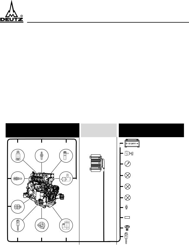
3.2System overview
3.2.1EMS 2 alone
EMS
Engine-side facility
Control unit
Flame system |
Flame system |
Engine speed |
solenoid valve |
temperature sensor |
|
Coolant |
Engine shut-off |
temperature sensor |
lifting magnet |
Oil pressure  sensor
Oil level switch |
Alternator |
Starter |
Vehicle-side/ System-side facility
Energy supply
Glow-start switch
Multi-functional display
Configurable outputs (e.g. indicator lamps)
Maintenance/service
Diagnostic lamp
Diagnostic button/ limp-home button
Diagnostic interfaces
•S, L line (ISO 9141)
•CAN bus (SAE J1939)
•SAE J1708 / J1587
Air filter differential pressure sensor
Coolant level switch
© 0702
© 0702 |
Page 59 |

EMS 2
System description
3.2.2EMS 2 in combination with MVS
DEUTZ scope of delivery Vehicle-side installation |
Service |
MVS |
Accelerator pedal |
Engine |
|
|
|
wiring |
Engine |
Vehicle |
|
harness |
|||
plug |
plug |
||
|
X26 CAN
EMS 2
Coolant
level sensor
Central plug
X23
© 0702
(EMS) |
|
|
(MVS)lampDiagnostic (MVS)buttonDiagnostic (EMS)lampIndicator Maintenance/service(EMS) (EMS)lampDiagnostic button/limpDiagnostic-home button |
Operating manual |
|
110 / 220 V~ |
|
|
|
|
|
|
Power supply |
|
|
or |
Software |
|
battery |
disc |
|
Interface |
|
|
User level |
|
|
depending on |
|
|
authorization |
|
Air filter |
Printer |
|
differential |
|
|
pressure switch |
|
|
|
Power supply |
|
|
or |
|
|
battery |
|
Interface |
110 / 220 V~ |
|
SAE J1708/ |
|
|
J1587 |
X25 |
|
|
|
Diagnostic plug
Part No.: 0419 9615
X22
3.2.3EMS 2 in combination with EMR
DEUTZ scope of delivery Vehicle-side installation |
Service |
Transfer plug |
EMR |
Terminating |
(EMS) |
|
|||
resistor (CAN) |
|
||
|
|
|
|
|
|
Accelerator |
(EMS)lampIndicator Maintenance/service(EMS) lampDiagnostic(EMS) button/limpDiagnostic-home button |
|
|
(EMR)lampFault |
|
|
|
pedal |
|
Engine |
|
|
|
wiring |
Engine |
Vehicle |
|
harness |
plug |
plug |
|
|
|
||
|
|
CAN |
|
|
|
X26 |
|
Air filter differential pressure switch
Operating manual |
|
110 / 220 V~ |
|
Power supply |
|
or |
Software |
battery |
disc |
Interface
User level depending on authorization
Printer
|
|
Power supply |
|
EMS 2 |
|
or |
|
Coolant |
|
battery |
|
Interface |
|
||
level sensor |
110 / 220 V~ |
||
SAE J1708/ |
|||
Central |
|||
plug |
J1587 |
X25 |
|
|
|
||
X23 |
Diagnostic plug |
|
|
|
Part No.: 0419 9615 |
|
X22
© 0702
Page 60 |
© 0702 |

EMS 2
System functions
4 System functions1
4.1Introduction
The EMS 2 serves to electronically monitor the engine. Its functions include:
Engine protection functions
●Warning the operator if limit values are exceeded or not achieved.
●Reduction in engine power.
●Emergency engine shut-off if operating data exceed or do not achieve the shut-off limits. Indication of maintenance requirements
in order to remind the operator and to reduce the consumption of operating media. The maintenance intervals can be obtained from the DEUTZ engine operating instructions, Chapter 5.1.
●in the event of excessive air filter differential pressure.
●if the number of operating hours leads to the achievement of the next maintenance requirements.
●if the load population reaches a maintenance limit.
●if calculation of the engine operating statuses (temperatures, speed, etc.) results in the oil change limit's being exceeded.
Data exchange
with other systems via the CAN interface, e.g. with the solenoid valve system (MVS):
●Transmission of the output reduction signal if limit values are exceeded.
●Engine shut-off via the CAN interface sets, e.g. the fuel injection quantity to zero.
●The integration of measurement data and fault messages via the CAN interface extends the input signals of the EMS 2 for executing engine protection functions and system diagnosis (see above).
●Transfer of the EMS 2 measurement data to other systems.
Diagnosis of the entire system
●System self-diagnosis, i.e. of the control unit, the sensors and the actuators.
●Display of engine operating data and self-diagnosis data on a PC (ISO9141 / RS232).
●Forwarding of the engine operating data to the SAE-J1708/1587 interface for diagnostic and display systems.
●Actuation of a telltale and output of a flashing code for fault identification.
Data recorder
Determination of the manner of operation, capacity utilisation and causes of engine failure.
●Recording the most important measurement variable signals.
●Determination of the load population.
●Storage of exceeded maintenance intervals.
●Documentation of hours of engine operation.
Engine operation display
● Output of a signal (telltale or relay) as soon as the speed exceeds 400 rpm.
1) Not all functions are available in all applications.
© 0702 |
Page 61 |

EMS 2
System functions
4.2Engine protection functions
4.2.1General
The following table contains an overview of the measurement variables which can be monitored, together with the relevant, possible engine protection functions.
Monitorable measurement variable |
|
Possible engine protection function1 |
||
|
Warning |
|
Power reduction |
Emergency engine |
|
|
|
|
shut-off |
Speed |
x |
|
|
x |
|
|
|
|
|
Oil temperature |
x |
|
x |
x |
|
|
|
|
|
Coolant temperature |
x |
|
x |
x |
|
|
|
|
|
Cylinder temperature 1 |
x |
|
x |
x |
|
|
|
|
|
Cylinder temperature 2 |
x |
|
x |
x |
|
|
|
|
|
Oil pressure |
x |
|
x |
x |
|
|
|
|
|
Coolant leveld |
x |
|
x |
x |
|
|
|
|
|
Oil level |
x |
|
x |
x |
|
|
|
|
|
Reserve signal T1 |
x |
|
x |
x |
|
|
|
|
|
1The configuration is programmed in the factory.
●If the measurement variable lies within the warning range, the diagnostic lamp is continuously illuminated. As a result of a command via the CAN interface to the EMR or MVS, the power is reduced. If the measurement variable exceeds/does not achieve the recovery threshold, the lamp is extinguished again.
●A reduction in power is only possible in combination with EMR and MVS.
●If the measurement lies within the shut-off range, emergency engine shut-off is carried out following the expiry of a waiting period. The diagnostic lamp flashes rapidly (frequency approx. 1 Hz). Shut-off is effected either
-via a shut-off solenoid or
-via the CAN interface on other electronic control units (EMR, MVS)
●Limit values which are exceeded or not achieved are documented in the fault memory.
●The fault message is output if the diagnostic button is actuated during engine standstill
-as a flashing code via the diagnostic lamp.
-with a notebook connected via the ISO9141 interface with the SERDIA diagnostic programme.
-via the ISO J1708/1587 interface according to standard.
●Starting prevention can be recognised via the rapid flashing of the diagnostic lamp (1Hz) in the event of engine standstill. If the EMS 2 has shut the engine off on the basis of the engine monitoring functions, restarting is prevented. The same applies if monitoring is carried out during standstill, and engine starting is blocked due e.g. a low coolant level.
●The engine can be restarted by switching the ignition off/on (terminal 15).
●Outputs may also be used to initialise lamps or relays if limit values are exceeded or not achieved, see Chapter entitled Outputs 5.2.
Page 62 |
© 0702 |
EMS 2
System functions
4.2.2Override-Funktion
●In safety-critical cases, emergency engine shut-off or output reduction can be suppressed with the limp-home button/diagnostic button (override signal). The EMS 2 is programmed in such a manner that the overwriting of these engine protection functions applies only for a specific period of time (limp-home time) or until the engine is shut-off.
●Depression of the button is confirmed via slow slashing (frequency approx. 0.5 Hz). The limp-home time (override time) begins again each time the button is depressed. Excessively frequent actuation of the button may damage the engine and lead to the expiry of the warranty (responsibility of the user).
●Override procedures are stored in the control unit.
●Following the expiry of the override time, the warning, reduction in power or the shut-off function are reactivated insofar as the relevant conditions for this are still present.
4.2.3Speed monitoring
Speed monitoring prevents engine damage as a result of excessive speed, and is defined prior to delivery depending on the combination (e.g. EMS with MVS) and model series. The speed signal can be supplied to the EMS 2 control unit in three ways:
●With a pick-up (magnetic speed sensor).
●Via the W terminal of the alternator.
●With data exchange via the CAN interface.
4.2.4Temperature monitoring
Depending on the engine model series, temperature sensors are available for engine oil, coolant, cylinder head 1 and 2, and reserve temperatures. Connection to the EMS 2 is carried out in two ways:
●Either via the inputs (see Chapter 5.1).
●Or via the CAN interface from other systems (MVS, EMR).
In addition, each time the temperature is exceeded, an output for initialising a lamp or a relay may be allocated, see Chapter entitled Outputs 5.2.
If the temperature falls below the recovery threshold, the diagnostic lamp is shut-off, and the power reduction or emergency shut-off engine protection functions are reset.
4.2.5Engine oil pressure and reserve pressure monitoring
Oil pressure monitoring is activated following the expiry of a fixed period of time after the engine has been started.
Depending on the application, the connection to the EMS 2 can be carried out in two ways:
●Via the inputs (see Chapter 5.1).
●Or via the CAN interface from other systems (MVS, EMR).
In addition, each time the temperature is exceeded, an output for initialising a lamp or a relay may be allocated, see Chapter entitled Outputs 5.2.
The warning limit is speed-dependent. In order to take pressure fluctuations into consideration, the oil pressure may fall below the warning limit for a speed-dependent period of time before the engine protection functions respond.
Following the expiry of the waiting period, the diagnostic lamp is continuously illuminated, insofar as the signal still lies in the warning range.
If the oil pressure exceeds the recovery threshold, the diagnostic lamp is shut-off, and the power reduction or emergency shut-off engine protection functions are reset.
Other pressures may be monitored depending on the application and the input assignment of the control unit.
© 0702 |
Page 63 |

EMS 2
System functions
4.2.6Filling level monitoring
Depending on the engine model series, sensors are available for engine oil, coolant or reserve fluid filling levels. Connection to the EMS 2 is carried out in two ways:
●Via the inputs (see Chapter 5.1).
●Or via the CAN interface from other systems (MVS, EMR).
If the warning threshold is not achieved, the diagnostic lamp is continuously illuminated. If the level rises above the recovery threshold due to the fluid's being topped up, the diagnostic lamp is shut-off.
Whilst engine is stationary
Fluid levels are monitored whilst the engine is stationary and the ignition is switched on (terminal 15). If the level falls below the shut-off limit, starting is prevented following a period of time which is specified in the factory. During this enquiry time, engine starting is released until starting is prevented.
During engine operation
The engine oil level is not monitored during engine operation. For the other fluid levels, monitoring during engine operation may also be programmed in the factory.
4.3Indication of maintenance requirements
Maintenance requirements may be indicated in the following manner:
●Via the maintenance/service lamp.
●Via the ISO 9141 interface with SERDIA.
After maintenance has been carried out, the maintenance messages can be reset with SERDIA or by connecting the L lead of the ISO9141 interface to ground for a minimum of 5 to a maximum of 10 seconds. The functions described in the following may report maintenance requirements, whereby each may initialise the maintenance lamp. An enquiry regarding the functions which are reporting the maintenance requirements can be made with the flashing code.
4.3.1With operating time counter
When the operating time counter reaches the next maintenance interval, the maintenance/service lamp is switched on, and the operator is reminded that maintenance is due.
4.3.2With load population
This function is only possible if the EMS 2 receives a load signal, e.g. from another electronic control unit via the CAN interface.
Maintenance is signalised with the aid of the maintenance/service lamp in accordance with the capacity utilisation of the engine throughout the engine operation period.
4.3.3With air filter differential pressure sensor
Depending on the engine model series, the engine is equipped with air filter differential pressure sensors. If the air filter differential pressure exceeds the specified limit during engine operation, i.e. at engine speeds in excess of 400 rpm, the maintenance/service lamp is switched on. The maintenance message is only reset if the air filter differential pressure returns to normal.
4.3.4Oil change interval calculation
This procedure is not applied in the case of all engine model series. The oil change interval depends on the manner in which the engine is operated. Calculation of the time of the next oil change is carried out with characteristic engine variables such as temperatures, speed, etc. When the calculation reached the oil change limit, the maintenance/service lamp is initialised.
Page 64 |
© 0702 |

EMS 2
System functions
4.4Data recording
4.4.1Data channels
The EMS 2 contains a maximum of 32 memory domains, in which a maximum of 32 measurement and calculation values (speed, temperatures, pressures, fluid levels, output signals, etc.) can be recorded. Some of these signals, e.g. charge air pressure and charge air temperature, can also be read in from engine governor systems via the CAN interface. In the relevant memory domains, identical measurement signals with different sampling rates can be recorded (most rapid sampling rate 5 Hz).
Depending on the spacing of the measurement points, measurement value recording of up to several thousand is possible. Either the current, maximum, minimum or the mean measurement values are recorded.
Depending on the engine model series and system expansion, values from the following table may be recorded:
Possible measurement signals
Charge air pressure
Charge air temperature
Operating time counter
Speed
Oil temperature
Coolant temperature
Cylinder head temperature 1
Cylinder head temperature 2
Reserve temperature 1
Reserve temperature 2
Engine oil pressure
Reserve oil pressure 1
Reserve oil pressure 2
Coolant level
Engine oil leve
Fluid level 1
Fluid level 2
Fluid level 3
Load signal
Fuel injection quantity (via CAN)
Output switching statuses
Power reduction signal
Override signal
Shut-off limit exceeded
Test operation mode
The EMS 2 is programmed with a sensible data recording configuration in the factory. Changes must be coordinated with head office, and are only possible with SERDIA.
Data recording is only carried out whilst the engine is running.
The data are read out with SERDIA, and are available in a standard format for commercially available graphics and evaluation programmes, e.g. Excel.
© 0702 |
Page 65 |
 Loading...