

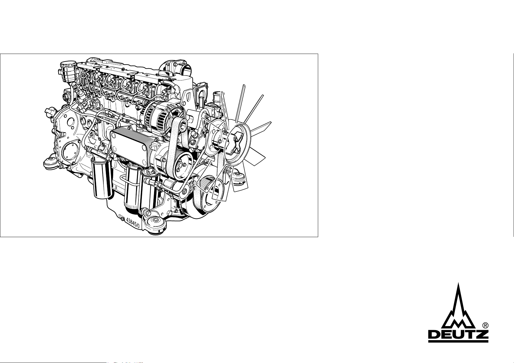
Operation Manual
TCD 2012 L04/06 V2
TCD 2013 L04/06 V2

z Read and observe the information in this
instruction manual. You will avoid accidents,
retain the manufacturer’s warranty and have
a fully functional, ready to use engine at your
disposal.
z This engine is exclusively for the purpose
according to the scope of delivery - defined
and built by the equipment manufacturer (use
for the intended purpose). Any use above and
beyond this is considered improper use. The
manufacturer will not be liable for damages
resulting from this. The user will bear the sole
risk in this case.
z Use for the intended purpose also includes
observance of the operating, maintenance
and repair instructions specified by the
manufacturer. The engine may only be used,
maintained and repaired by persons who are
familiar with it and instructed in the dangers.
z The pertinent rules for the prevention of
accidents and other generally recognised
safety and industrial medicine rules must be
observed.
z When the engine is running there is a danger
of injury caused by:
- rotating / hot components
- engines with extraneous ignition
- ignition systems (high electrical voltage)
Contact must be avoided!
z The manufacturer will not be liable for damages
resulting from unauthorised modification to the
engine.
Equally, manipulations to the injection and control
system can affect the engine’s performance
and the exhaust characteristics. Compliance
with environmental regulations will no longer
be guaranteed in this case.
z Do not alter, obstruct or block the area of the
cool air supply to the fan.
The manufacturer will accept no liability for
damages resulting from this.
z Only DEUTZ original parts may be used when
carrying out maintenance/repair work on the
engine. These have been designed especially
for your engine and ensure a trouble-free
operation.
Failure to observe this will lead to voiding of the
warranty!
z Maintenance/cleaning work on the engine
may only be carried out when the engine is not
running and has cooled down.
When doing this, make sure that the electrical
system is switched off (remove ignition key).
The specifications for accident prevention
with electrical systems (e.g. VDE-0100/-0101/
-0104/-0105 Electrical protective measures
against dangerous touch voltages) must be
observed.
Cover all electrical components tightly when
cleaning with liquids.
z Do not work on the fuel system while the
engine is running - Danger to life.
Wait (1 minute) for the engine to come to a
standstill (pressure release), as system is
under high pressure: there is a - Danger to
life.
During the first trial run do not stand in the
danger area of the engine (danger due to high
pressure of leaks) - Danger to life.
- In case of leaks immediately contact
the workshop.
- When working on the fuel system ensure that
the engine is not unintentionally started during
repairs - Danger to life.

Engine number:
Operation Manual
TCD 2012 L04/06 V2
TCD 2013 L04/06 V2
312 1890 en
Please enter the engine number here. This will
simplify the handling of customer service, repair
and spare parts queries (see Section 2.1).
Illustrations and data in this instruction manual are
subject to technical changes in the course of
improvements to the engines. Reprinting and
reproductions of any kind, even in part, require
our written permission.

Foreword
Dear customer,
The liquid-cooled engines made by DEUTZ are
developed for a wide variety of applications.
An extensive range of variants ensures that
the respective special requirements are met.
Your engine is equipped according to the
installation, i.e. not all the parts and
components described in this instruction
manual are installed on your engine.
We have done our best to clearly identify the
differences, so that you can easily find the
operating, maintenance and repair
instructions relevant to your engine.
Please read these instructions before you
start your engine and observe the operating
and maintenance instructions.
We are at your service for any questions you
may have in this matter.
Your
DEUTZ AG
© 2005

Contents
1. General
2. Engine description
2.1 Engine type
2.1.1 Company plate
2.1.2 Location of company plate
2.1.3 Engine number
2.1.4 Cylinder numbering
2.2 Engine diagrams
2.2.1 Operation side
TCD 2012 L04 2V
2.2.2 Starter side
TCD 2012 L04 2V
2.2.3 Operation side
TCD 2012 L06 2V
2.2.4 Starter side
TCD 2012 L06 2V
2.2.5 Operation side
TCD 2013 L04 2V
2.2.6 Starter side
TCD 2013 L04 2V
2.2.7 Operation side
TCD 2013 L06 2V
2.2.8 Starter side
TCD 2013 L06 2V
2.3 Lube oil circuit
2.3.1 Lube oil diagram (example)
2.4 Fuel circuit
2.4.1 Fuel diagram
2.5 Coolant circuit
2.5.1 Coolant diagram (example)
2.6 Electrics
2.6.1 Electrical cable connections for
monitoring
3. Operation
3.1 Initial commissioning
3.1.1 Filling engine oil
3.1.2 Filling fuel
3.1.3 Filling / bleeding cooling system
3.1.4 Other preparations
3.2 Starting
3.2.1 Electrical starting
3.3 Operation monitoring
3.3.1 Engine oil pressure
3.3.2 Coolant temperature
3.3.3 Coolant level
3.4 Shutting down
3.4.1 Electrical shutdown
3.5 Operating conditions
3.5.1 Winter operation
3.5.2 High ambient temperature,
high altitude
4. Operating substances
4.1 Lube oil
4.1.1 Quality
4.1.2 Viscosity
4.2 Fuel
4.2.1 Quality
4.2.2 Winter fuel
4.3 Coolant
4.3.1 General
4.3.2 Coolant preparation
5. Maintenance
5.1 Maintenance schedule
5.2 Maintenance diagram
5.3 Maintenance work carried out
6. Care and maintenance
work
6.1 Lubrication system
6.1.1 Oil change intervals
6.1.2 Checking oil level, changing engine oil
6.1.3 Changing oil filter
6.1.4 Cleaning / changing oil filter (cup)
6.2 Fuel system
6.2.1 Changing fuel filter
6.2.3 Fuel pre-filter, changing / bleeding
filter insert
6.3 Cooling system
6.3.1 Cleaning intervals
6.3.2 Cleaning cooling system
6.3.3 Emptying cooling system
6.3.4 Filling / bleeding cooling system
6.4 Combustion air filter
6.4.1 Cleaning intervals
6.4.2 Emptying cyclone pre-separator
6.4.3 Cleaning oil bath air filter
6.4.4 Dry air filter
6.5 Belt drive
6.5.1 Checking V-belt
6.5.2 Changing V-rib belt
6.5.3 Checking wear limit of V-rib belt
6.6 Setting work
6.6.1 Checking valve clearance,
setting if necessary
6.6.2 Setting control piston clearance
in exhaust gas recirculation (EGR)
6.6.3 Diagram for setting valve / control
piston clearance
© 2005

Contents
6.7 Add-on parts
6.7.1 Battery
6.7.2 Three-phase current generator
6.7.3 Transportation suspension
7. Faults, causes and remedies
7.1 Fault table
7.2 Engine management
7.2.1 Engine protection function of the
electronic engine controller EMR3
7.2.2 Using the diagnosis button
7.2.3 Table of fault blink codes
8. Engine corrosion protection
8.1 Corrosion protection
9. Technical data
9.1 Engine and setting data
9.2 Screw tightening torques
9.3 Tools
10. Service
© 2005
General
DEUTZ Diesel Engines
are the product of many years of research
and development. The resulting know-how,
coupled with stringent quality standards,
guarantee their long service life, high reliability
and low fuel consumption.
It goes without saying that DEUTZ Diesel
Engines meet the highest standards for environmental protection.
Beware of Running Engine
Care and Maintenance
Sound care and maintenance practices will
ensure that the engine continues to meet the
requirements placed on it. Recommended
service intervals must be observed and
service and maintenance work carried out
conscientiously. Special care should be taken
under abnormally demanding operating
conditions.
Safety
Service
1
Please contact one of our authorized service
representatives in the event of breakdowns
or for spare parts inquiries. Our trained
specialists will carry out repairs quickly and
professionally, using only genuine spare
parts. Original parts from DEUTZ AG are
always produced in accordance with stateof-the-art technology.
The Technical Circulars listed in the instruction
manual are obtainable from your DEUTZ
partner.
Please turn to the end of this manual for
further service information.
Asbestos
Shut the engine down before carrying out
maintenance or repair work. Ensure that the
engine cannot be accidentally started. Risk of
accidents!
When working on the running engine, work
clothing must be close fitting.
Observe industrial safety regulations when
running the engine in an enclosed space or
underground.
When the work is complete, be sure to refit
any panels and guards that may have been
removed.Never fill the fuel tank while the
engine is running.
This symbol is used for all safety
warnings which, if not
observed, present a direct
danger to life and limb for the
person involved. Please follow
them carefully. The attention of operating
personnel should be drawn to these safety
instructions. General safety and accident
prevention regulations laid down by law must
also be observed.
DEUTZ original parts are
asbestos-free.
© 2005

2.1 Engine type
2.2 Engine diagrams
2.3 Lube oil circuit
2.4 Fuel circuit
2.5 Coolant circuit
2.6 Electrics
Engine description
2
© 2005
Engine description
2.1 Engine type
2
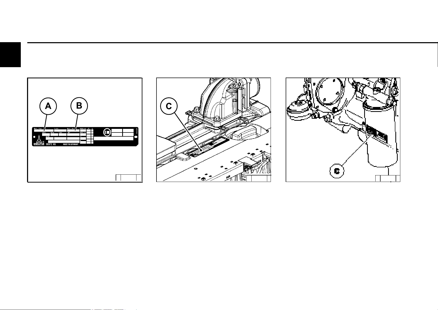
2.1.1 Company plate
© 35 985 0
The engine type A, engine number B and the
power data are stamped on the company plate.
The engine type and number must be stated
when purchasing spare parts.
2.1.2 Location of company plate
© 38 987 1
The company plate C is fixed to the cylinder
head cover or the crankcase.
© 43 834 0
© 2005
2.1 Engine type
Engine description
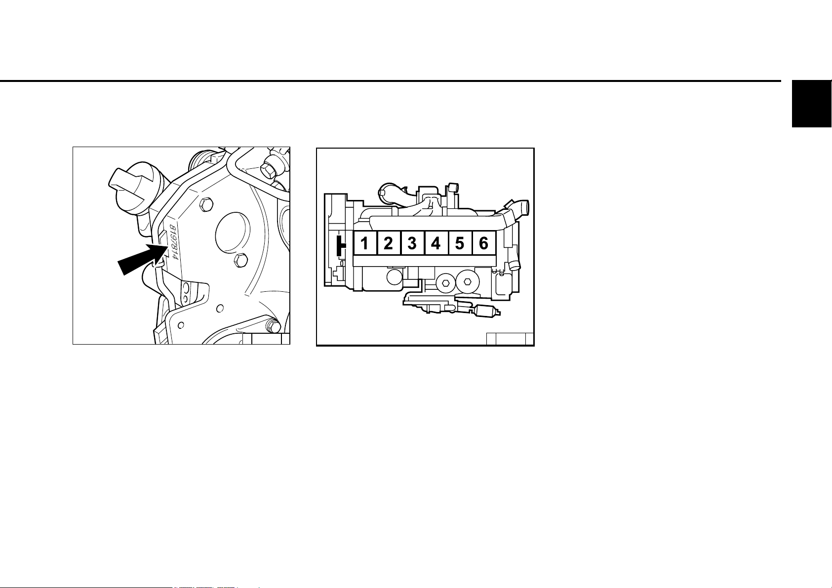
2.1.3 Engine number
© 43 833 0
The engine number is stamped on the crankcase
(arrow) and on the company plate.
2.1.4 Cylinder numbering
2
© 38989 0
The cylinders are counted consecutively, starting
from the flywheel.
© 2005

Engine description
2.2 Engine diagrams
2
2.2.1 Operation side
TCD 2012 L04 2V
1 Oil filler
2 Combustion air inlet
3 Cover
4Fan
5 Generator
6 Fuel pump
7 Tension pulley with torsion spring
8 Oil cooler
9 Exchangeable fuel filter
10 Exchangeable lube oil filter
11 Oil tray
12 Hydraulic pump or compressor mounting
possibility
13 Flywheel
14 Crankcase bleeding valve
15 Transport eyes
16 Charge air pipe
17 Fuel control unit
© 2005
© 43 302 0
2.2 Engine diagrams
Engine description
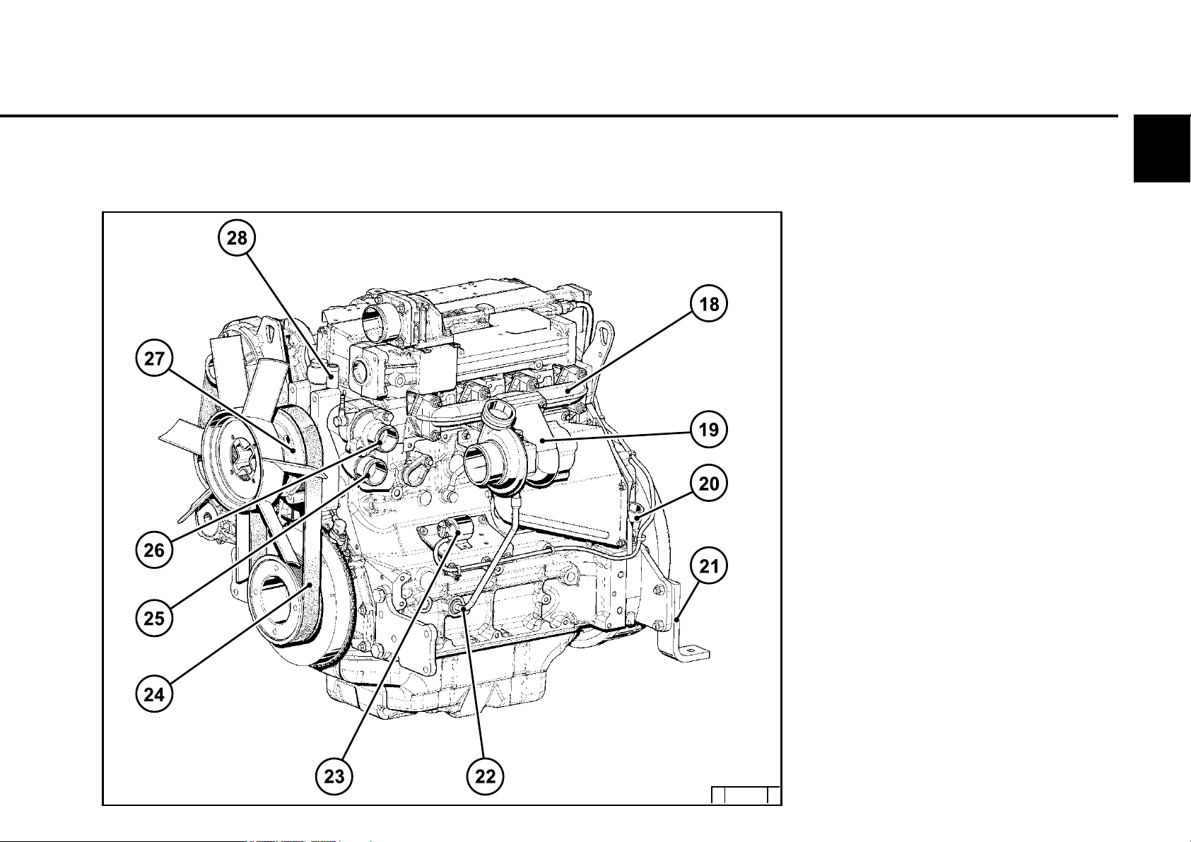
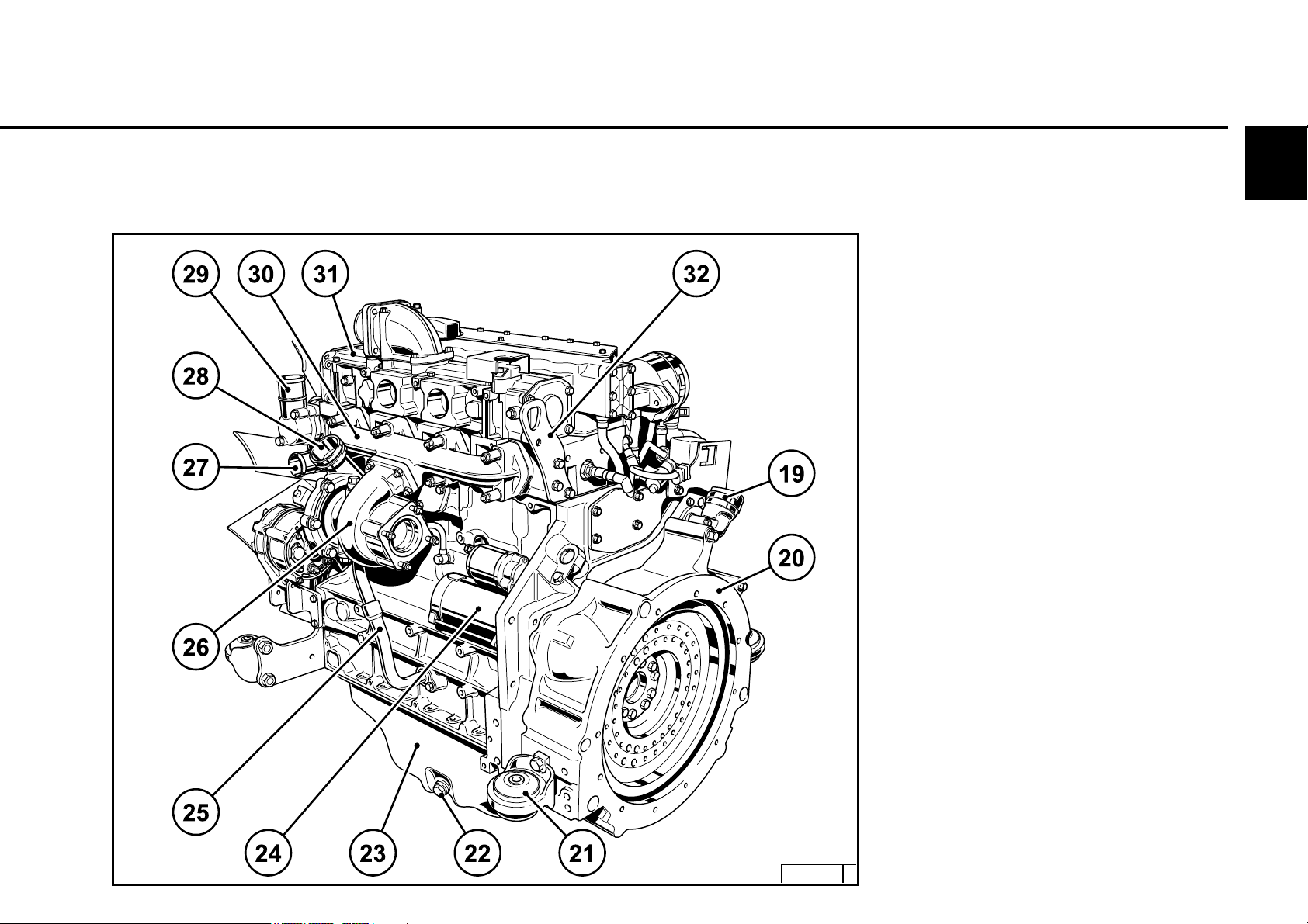
2.2.2 Starter side
TCD 2012 L04 2V
2
18 Exhaust manifold
19 Turbocharger
20 Oil filler (optional)
21 Engine mounting
22 Oil return line from turbocharger
23 Relay (starter)
24 V-rib belt
25 Coolant inlet
26 Coolant outlet
27 Coolant pump
28 Connection cabin heater or
compensation line
© 44 303 0
© 2005
2
Engine description
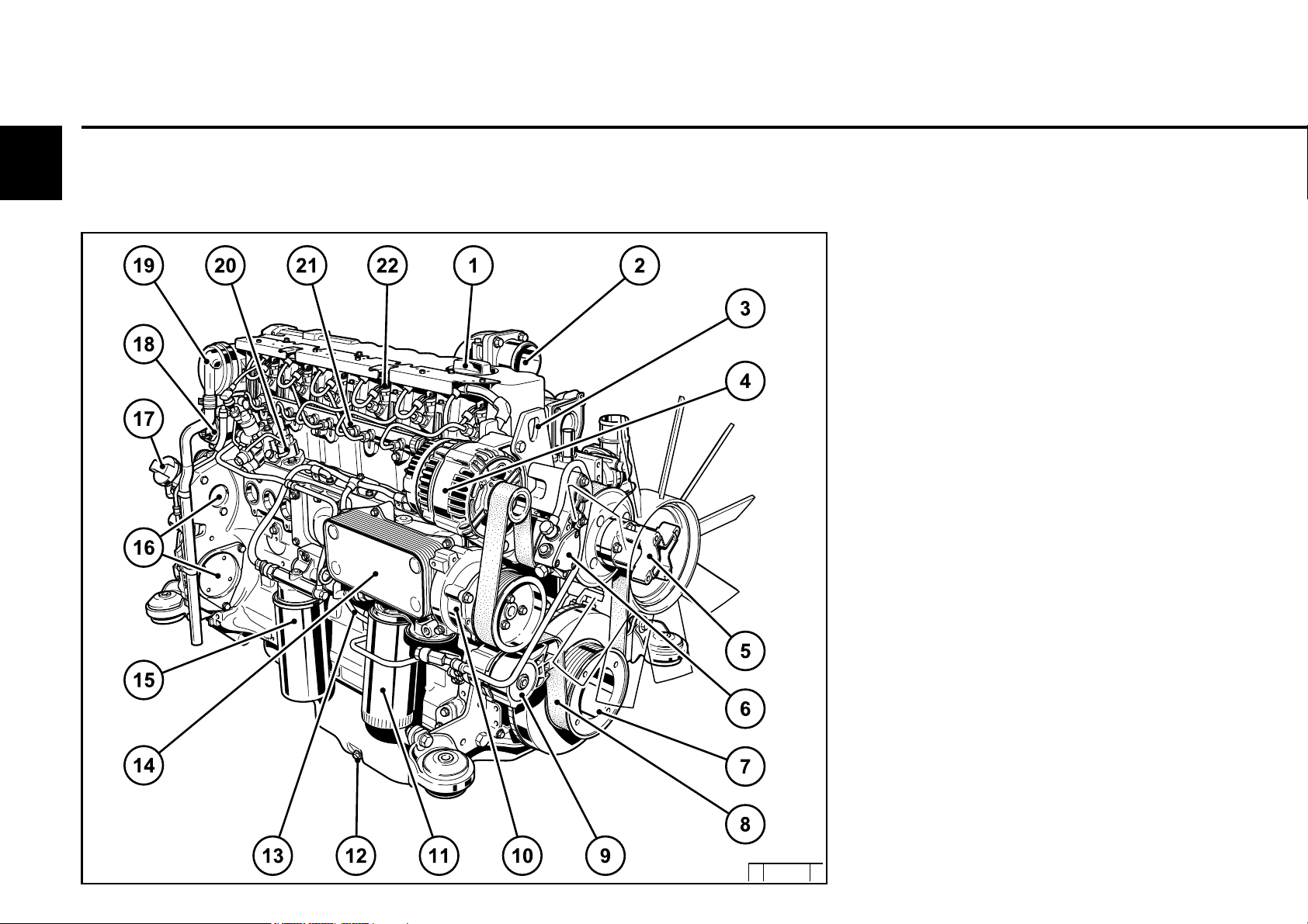
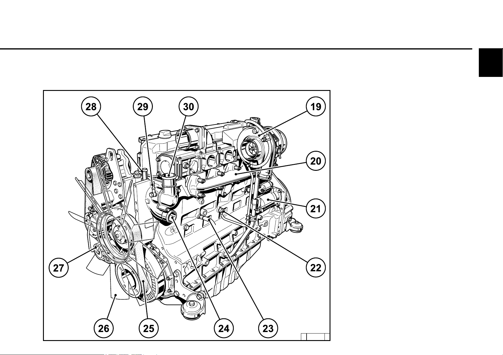
2.2.3 Operation side
TCD 2012 L06 2V
2.2 Engine diagrams
1 Oil filler
2 Combustion air inlet
3 Transport eyes
4 Generator
5 Fan hub
6 Fuel pump
7 V-rib belt drive on crankshaft
8 V-rib belt
9 Tension pulley with torsion spring
10 Coolant pump
11 Exchangeable lube oil filter (1x optional)
12 Oil drain screw
13 Oil dipstick
14 Lube oil cooler
15 Exchangeable fuel filter
16 Hydraulic pump or compressor installation
(optional)
17 Oil filler (optional)
18 Plug to control unit
19 Crankcase bleeding valve
20 High-pressure pump (2)
21 Rail
22 Injector
© 2005
© 43 828 1
2.2 Engine diagrams
Engine description
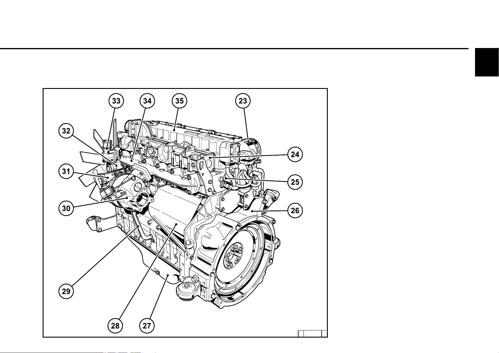
2.2.4 Starter side
TCD 2012 L06 2V
2
23 Crankcase bleeding valve
24 Charge air pipe
25 Solenoid valve for exhaust gas recirculation
26 SAE housing
27 Oil tray
28 Starter cover
29 Oil return line from turbocharger
30 Exhaust turbocharger
31 Charge air connection to charge air cooler
32 Coolant inlet
33 Coolant outlet
34 Exhaust manifold
35 Cylinder head cover
© 43829 2
© 2005
Engine description
2.2 Engine diagrams
2
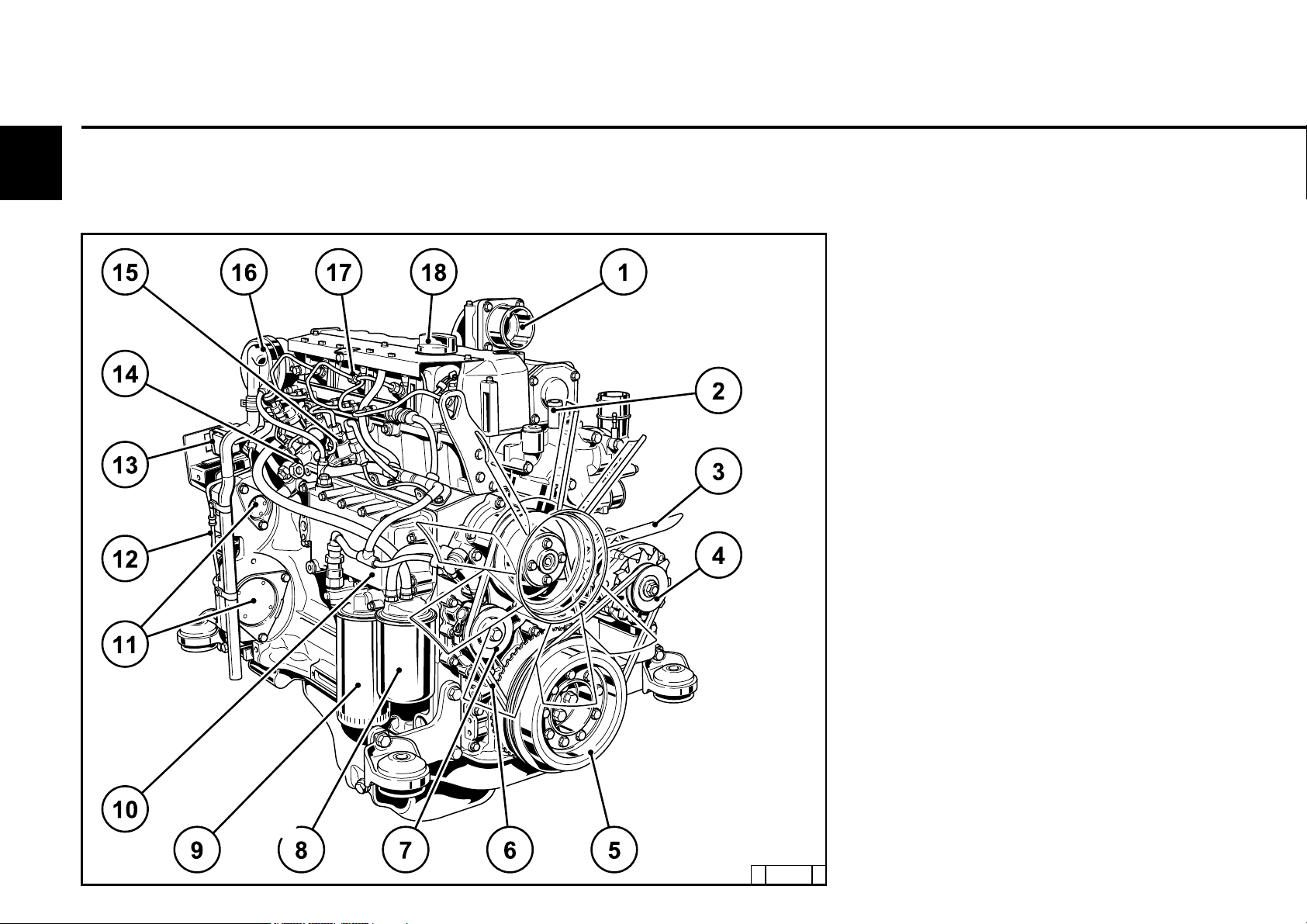
2.2.5 Operation side
TCD 2013 L04 2V
1 Combustion air inlet
(heating flange installation facility, optional)
2 Connection cabin heater or compensation
line
3 Fan (drive coolant pump)
4 Generator
5 Belt pulley on crankshaft
6 V-belt
7 Fuel pump drive
8 Exchangeable fuel filter
9 Exchangeable lube oil filter
10 Oil cooler
11 Drive facility (e.g. hydraulic pump,
optional)
12 Oil return line crankcase bleeding
13 Plug to control unit
14 Fuel control unit
(Electronic Control Unit)
15 High-pressure pump
16 Crankcase bleeding valve
17 Injector
18 Oil filler
© 2005
© 43 899 1
2.2 Engine diagrams
Engine description
2.2.6 Starter side
TCD 2013 L04 2V
2
19 Oil filler (optional)
20 SAE housing
21 Engine mounting
22 Oil drain screw
23 Oil tray
24 Starter
25 Lube oil return from turbocharger
26 Turbocharger
27 Coolant inlet
28 Charge air connection to cooler
29 Coolant outlet
30 Exhaust manifold
31 Charge air pipe
32 Transport eyes
© 43 900 3
© 2005

Engine description
2.2 Engine diagrams
2
2.2.7 Operation side
TCD 2013 L06 2V
1 Combustion air inlet
2 Oil filler
3 Transport eyes
4 Generator
5 Coolant pump
6 Exchangeable lube oil filter
7 Exchangeable fuel filter
8 Oil tray
9 Oil dipstick
10 Oil drain screw
11 Oil return line crankcase bleeding
12 Engine mounting
13 SAE housing
14 Plug to control unit
15 High-pressure pump
16 Rail
17 Crankcase bleeding valve
18 Injector
© 2005
© 43 924 0
2.2 Engine diagrams
Engine description
2.2.8 Starter side
TCD 2013 L06 2V
2
19 Turbocharger
20 Exhaust manifold
21 Starter
22 Lube oil line to turbocharger
23 Coolant drain screw
24 Coolant inlet
25 V-rib belt
26 Fan
27 Tension pulley with torsion spring
28 Connection compensation line
29 Ventilation line to compensation tank
30 Coolant outlet from engine to cooler
© 43 925 1
© 2005
Engine description
2.3 Lube oil circuit
2
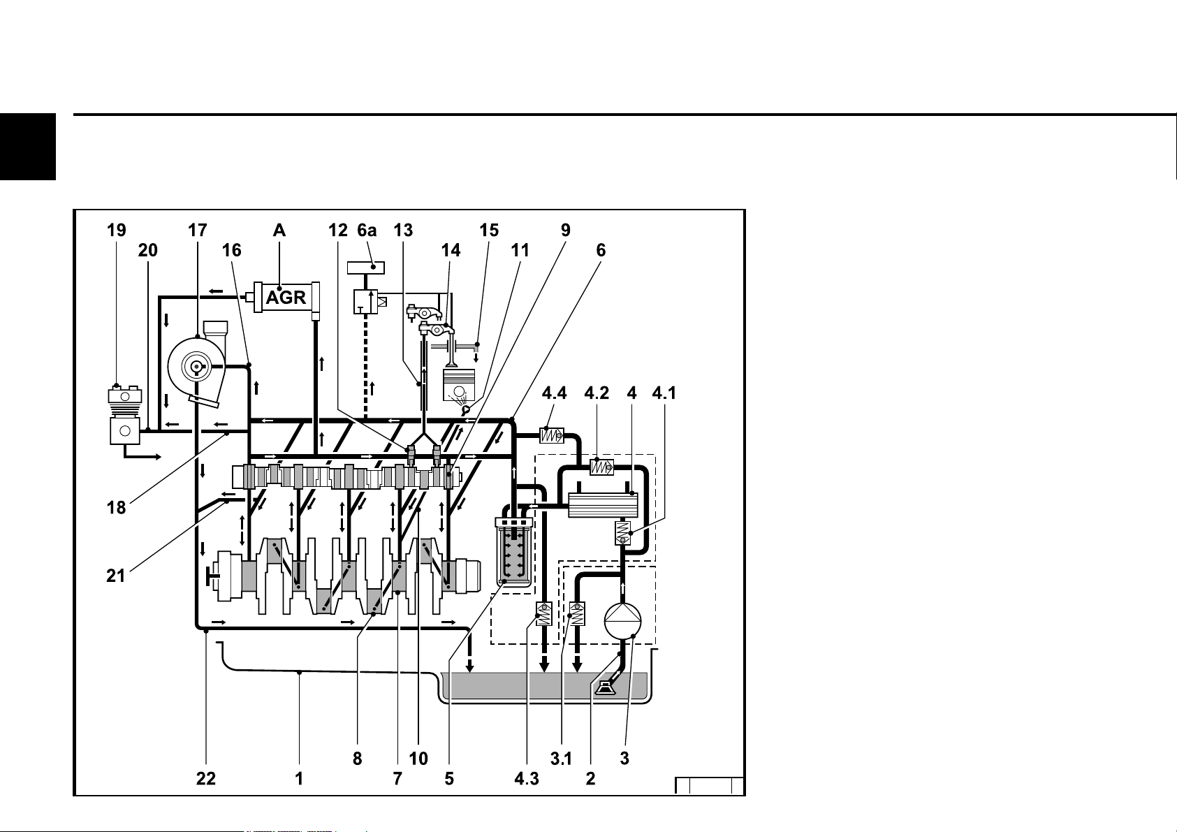
2.3.1 Lube oil diagram (example)
1 Oil tray
2 Intake pipe
3 Lube oil pump
3.1 Safety valve
4 Lube oil cooler
4.1 Return shutoff valve (only in 2012)
4.2 By-pass valve
4.3 By-pass valve oil filter
4.4 Pressure control valve
5 Exchangeable lube oil filter
6 Main oil pipe
6a Internal exhaust gas recirculation
7 Crankshaft bearing
8 Con rod bearing
9 Camshaft bearing
10 Line to injection nozzle
11 Injection nozzle for piston cooling
12 Tappet with rocker arm pulse lubrication
13 Stop rod, oil supply for rocker arm
lubrication
14 Rocker arm
15 Return line to oil tray
16 Lube oil line toexhaust turbocharger
17 Exhaust turbocharger
18 Return line from compressor 2x
19 Compressor or hydraulic pump
20 Oil line to compressor or hydraulic
pump
21 Return line from exhaust turbocharger
© 2005
© 43 893 0
© 39 012 2
2.4 Fuel circuit
Engine description
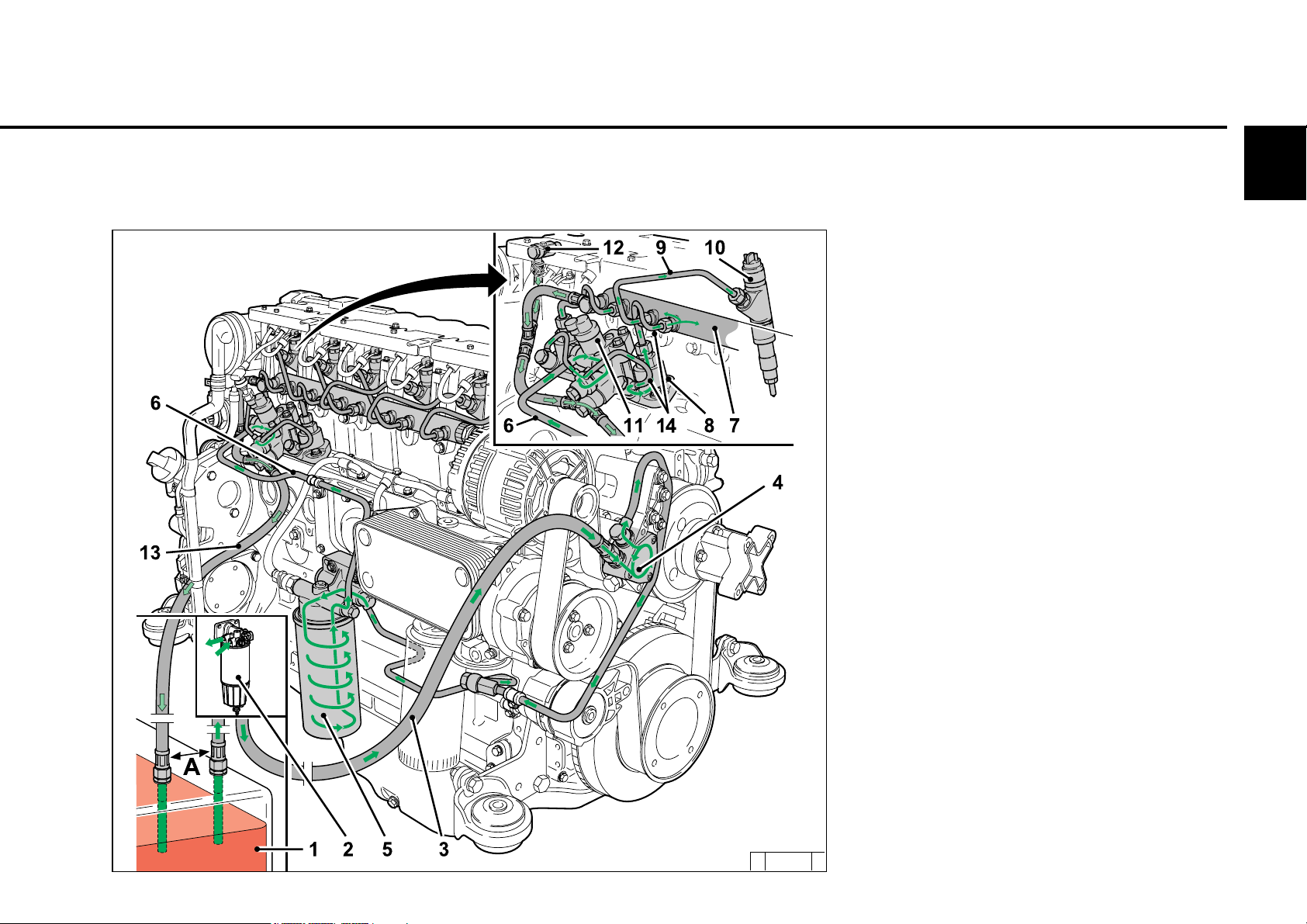
2.4.1 Fuel diagram
2
1 Fuel container
2 Fuel pre-filter with pre-pressure pump
possibility for filling the low pressure area
(to be provided by the customer)
3 Line to fuel pump
4 Fuel pump
5 Fuel filter
6 Fuel supply line to fuel control unit
7 Rail
8 High-pressure pump
9 Fuel line to injector
10 Injectors
11 Control block FCU (Fuel Control Unit)
12 Fuel return at the cylinder head
13 Fuel return line to the tank
14 Fuel lines from the control block to the high -
pressure pumps and to the rail
A min. distance 500 mm
© 43 844 1
© 2005
2
Engine description
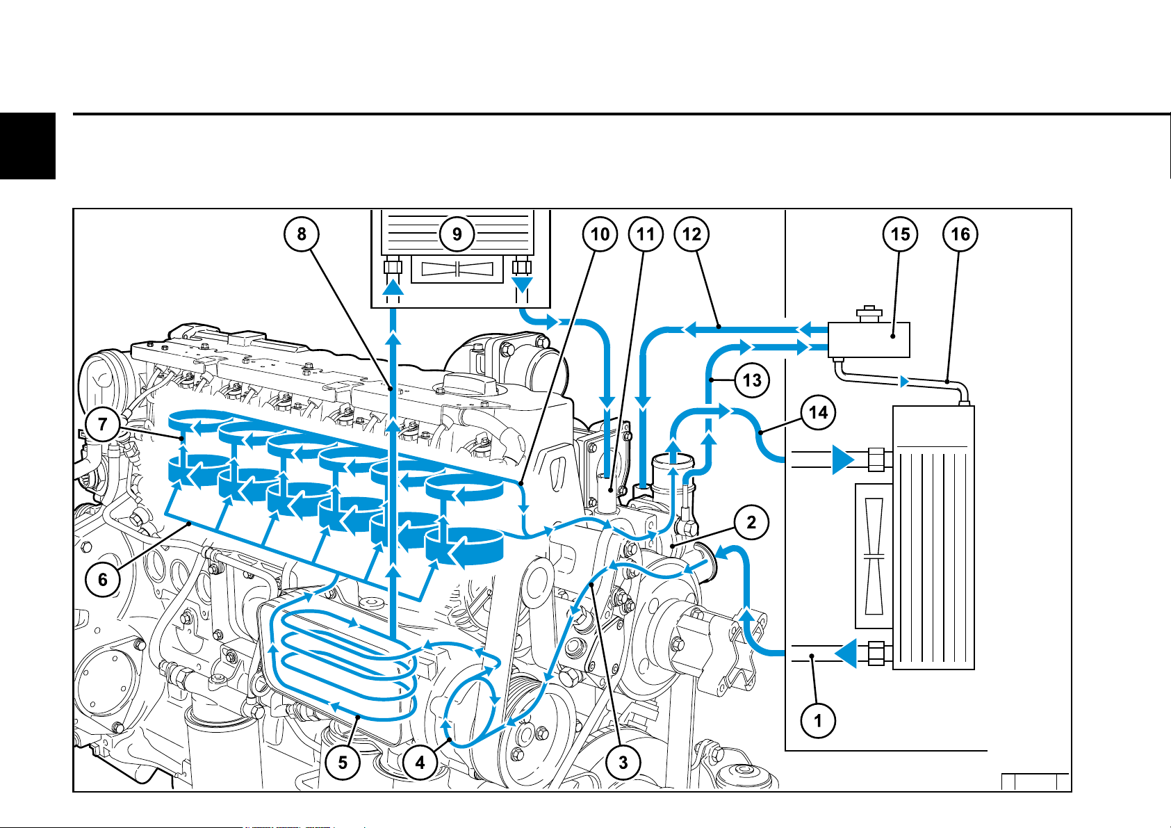
2.5.1 Coolant diagram
(example)
2.5 Coolant circuit
© 2005
© 43 897 4

2.5 Coolant circuit
1 Coolant outlet at the cooler
2 Thermostat
3 Coolant feed line to pump
4 Coolant pump
5 Lube oil cooler
6 Cylinder cooling
7 Cylinder head cooling
8 Coolant inlet to heating
9 Heating
10 Coolant to thermostat
11 Heating connection
12 Compensation line
13 Ventilation line to compensation tank
14 Coolant outlet to cooler
15 Compensation tank
16 Compensation line to heat exchanger
Engine description
2
© 2005
Engine description
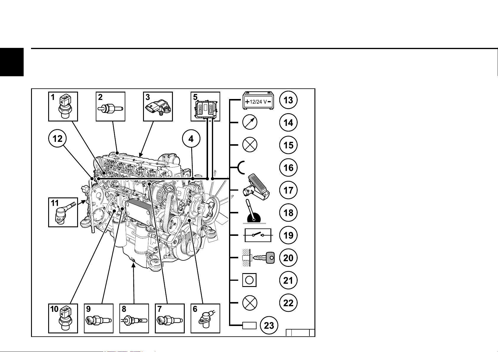
2.6 Electrics
2
2.6.1 Electrical cable connections
for monitoring
1 Solenoid valve EGR (optional)
2 Coolant temperature
3 Charge air pressure/temperature
transmitter
4 Connection facility example:
Control unit not mounted on the engine
5 Engine control unit
6 Speed governor via crankshaft
7 Rail pressure, on side of rail
8 Oil level transmitter (optional)
9 Oil pressure transmitter
10 Fuel pressure
11 Speed governor via camshaft
12 Central plug (for engine control)
13 Power supply (battery)
14 Multifunction displays
15 Outputs (configurable, e.g. for lamps,
torque (PWM), speed, engine running
signal, etc.)
16 Inputs (configurable)
(PWM/digital/analogue)
17 Accelerator pedal
18 Hand throttle (optional)
19 Switch functions (optional, e.g. for P factor,
controller type, roof curves, fixed
speeds, (etc. also multistage
switches))
20 Key switch
Start/stop
21 Diagnosis button
22 Fault light with blink code
23 Diagnosis interface / CAN-Bus
© 2005
© 43 926 0

2.6 Electrics
Other application-side components (depending on the application)
z Water trap fuel filter, see chap. 6.2.3
z Override key, see chap. 3.3.1 (for temporary bypassing of the engine protection
functions)
z Coolant level transmitter
z Separate engine stop switch
z Fan control
z Switch for brake contact, engine brake, clutch
z Drive speed sensor, drive speed control unit
(+ - keys, for speed increase reduction)
z Cold start aid control lamp, see chap. 3.2.1
If there is a serious fault, e.g. the heating flange draws current although the control unit
does not control it, this lamp flashes. The power supply to the heating flange must then
be disconnected separately (overheating protection heating flange).
Engine description
2
© 2005

3.1 Initial commissioning
3.2 Starting
3.3 Operation monitoring
3.4 Shutting down
3.5 Operating conditions
Operation
3
© 2005
Operation
3.1 Initial commissioning
3
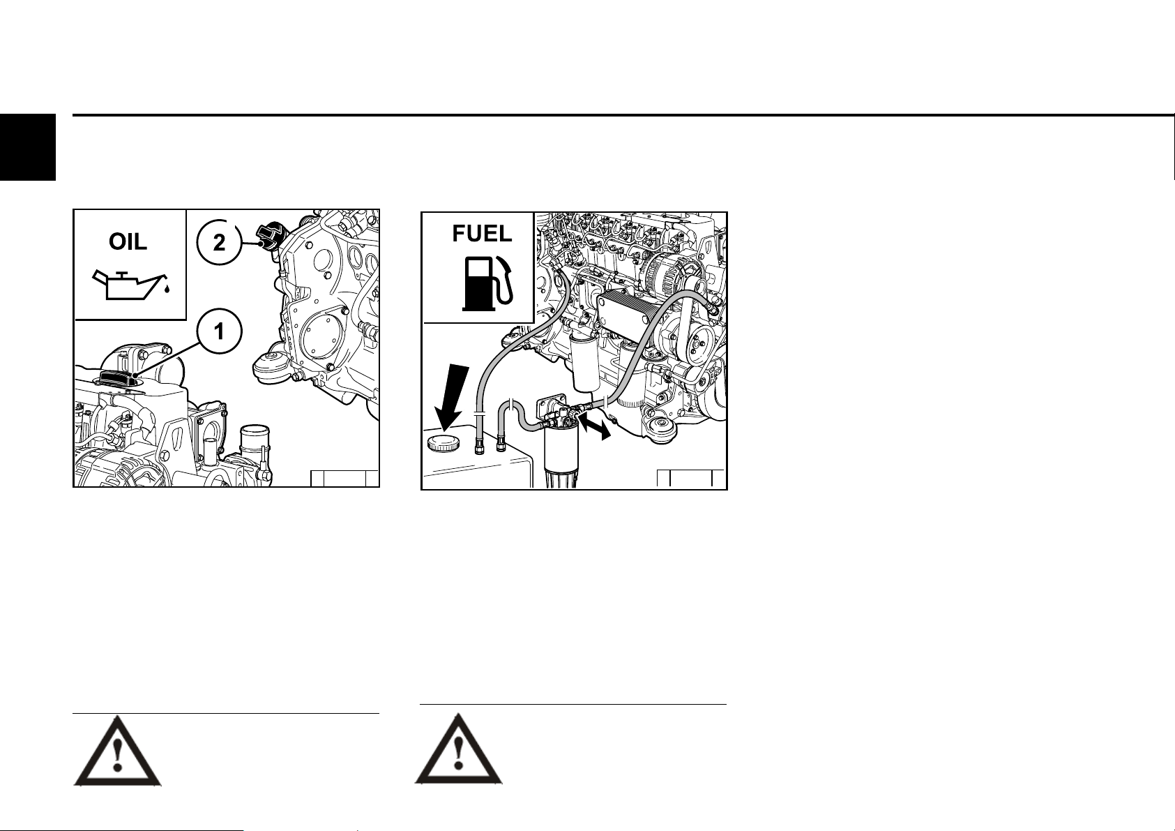
3.1.1 Filling engine oil
© 43 838 2
The engines are generally supplied without oil
filling.
Fill engine with lube oil through the oil filler (1)
on the cylinder head cover. Alternatively, you
can fill on the wheel box (2) or on the side of
the crankcase.
For oil filling amount see 9.1.
For quality and viscosity of oil see 4.1.
3.1.2 Filling fuel
© 43 843 2
Only use clean, standard, branded diesel fuel. For
fuel quality see 4.2.
Depending on the outdoor temperature, use
either summer or winter diesel fuel.
Bled the fuel low pressure system after
filling, see 6.2.3.
Additional venting of the fuel system by
a 5 minute trial run in idle or low load is
absolutely essential.
© 2005
Oil may not be filled into the dust
collecting tank of the preseparator, if this is present.
Only re-fuel when the engine is not
running!
Pay attention to cleanliness!
Do not spill any fuel!
3.1 Initial commissioning
Operation
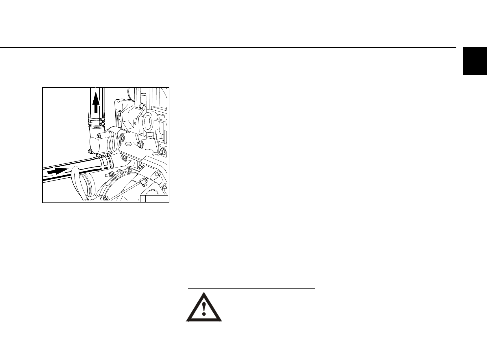
3.1.3 Filling / bleeding
cooling system
© 43 846 0
z Connect connection coolant outlet 1 and coolant
inlet 2 to the cooling system. Connect the lead
line from the compensation tank to the water
pump or to the coolant inlet pipe 2.
z Connect the bleed lines from the engine and
poss. from the cooler to the compensation
tank.
z Fill the cooling system through the
compensation tank.
z Close the compensation tank with the valve.
z Start the engine and run warm until the
thermostat opens (line 1 heats up).
z Engine run with open thermostat 2 - 3 minutes.
z Check the coolant level in the compensation
tank and top up the coolant if necessary.
z Repeat the process with engine start if
necessary.
Never operate the engine without
coolant (not even briefly).
3.1.4 Other preparations
3
z Check battery and cable connections, see
6.7.1.
z Trial run
- After preparations carry out a short
trial run of approx. 10 min.
Do not fully load the engine.
During and after the trial run
- Check engine for tightness.
With engine not running
- Check oil level, re-fill oil if necessary, see
6.1.2
- Check V-belt, re-tighten if necessary, see
6.5.
z Running-in
Check the oil level twice a day during the
running-in phase.
After the running-in phase, checking once a
day is sufficient.
© 2005
3
Operation
3.2.1 Electrical starting
3.2 Starting
without cold start aid
Before starting make sure that
there is nobody in the engine/
work machine danger area.
After repairs: Check that all
protective equipment is
mounted and all tools have been removed
from the engine.
When starting with heating plugs/heating
flange, do not use additional start aids (e.g.
injection with start pilot)! Danger of accidents!
z Engine is electronically controlled by
Example: EMR3 (electronic engine control)
- engine is programmed and supplied with
the necessary function configurations.
z As far as possible separate engine from
driven devices by disconnecting.
z Engine connector plug must be connected
by the customer (e.g in driver’s cab/
device) to at least:
- Supply voltage
- Torque output
- Speed output.
z Warm up the engine for approx. 30 seconds
at a low idling speed.
z Do not run up the engine immediately to
high idling speed / full load operation from
cold.
If the starter is connected by a relay on
the EMR3,
- the maximum starting time is limited by
the EMR3.
- the pause between two start attempts
is given by the EMR3.
© 26 411 0
- If the touch start function is programmed, a
short start command with the ignition key
suffices in position 2 or, if available, by a start
button.
The start is then continued automatically by the
EMR3.
- For special applications, the EMR3 can be
programmed by data record so that the control
unit performs other automatic start attempts if
the engine fails to start.
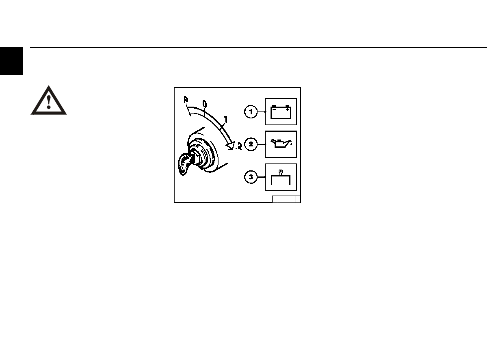
z Insert key
- Step 0 = no operating voltage.
z Turn key to the right
- Step 1 = operating voltage,
- Warning lights light up.
z Turn the key further to the right against the
spring load.
- Step 2 = start
z Release key as soon as the engine starts up.
- Warning lights go out.
Start the engine for a maximum of 20 seconds
uninterrupted. If the engine does not start up, wait
for one minute and then repeat the starting
process. If the engine does not start up after two
starting processes, determine the cause as per
fault table (see 7.1).
If the engine does not start and the diagnostic lamp
flashes, the EMR3 system has activated the start
lock to protect the engine.
The start lock is released by switching off the
system with the ignition key for about 30 seconds.
© 2005
3.2 Starting
Operation
with cold start aid
Heating plug/heating flange
© 26 411 0
z Insert key.
- Step 0 = no operating voltage.
z Turn key to the right.
- Step 1 = operating voltage,
- Warning lights 1+2+3 light up.
- Pre-heat until heating indicator goes out. If the
pre-heating indicator flashes, there is an
error, e.g. pre-heating relay sticking which
can fully discharge the battery at standstill.
- Engine is ready for operation.
z Turn the key further to the right against the
spring load to
- Step 2 = start
z Release key as soon as the engine starts up.
- Warning lights go out.
3
Caution: Engine must start within 30 seconds, if
not, repeat the starting process.
© 2005
Operation
3.3 Operation monitoring
3
The EMR3 system monitors the engine condition
and itself.
The states are indicated by the diagnostic
lamp.
Lamp test:
z The diagnostic lamp lights for about 2s after
ignition (ignition lock stage 1).
Steady light:
z There is an error in the system or a variable of
the engine (temperature, pressure, etc.) is in
the warning area. Depending on the error, the
performance of the engine may be reduced by
the EMR3 to protect the engine so that it is not
in danger.
Fast flashing:
z Attention, the engine is in danger and
must be switched off.
z Depending on the application, the
control unit switches the engine off
automatically.
z The control unit may also specify an idle speed
to cool the engine before shutting down.
z There may be a start lock after stopping the
engine.
z Additional control lamps e.g. for oil pressure or
oil temperature may be on.
z The override key can bypass the reduction in
performance to avoid critical situations, as
well as delay the automatic shutdown or
bypass a start lock. This overwriting of the
engine protection functions is logged in the
control unit.
z The start lock is released by switching off the
system with the ignition key for about 30
seconds.
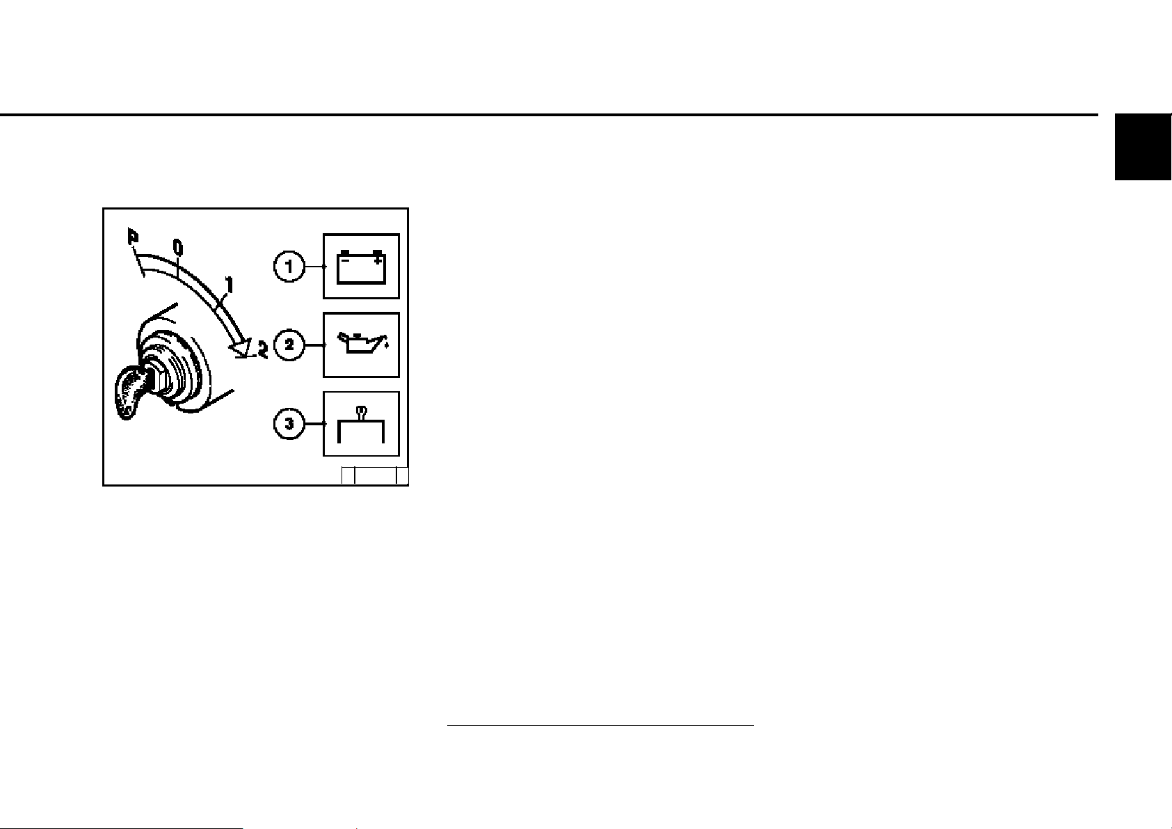
3.3.1 Engine oil pressure
Oil pressure light
© 25 752 1
z The oil pressure light comes on for about 2s
after switching on the system.
z The oil pressure light must be off when the
engine is running.
Oil pressure gauge
© 25 754 0
z Oil pressure gauge shows the lube oil pressure
(minimum lube oil pressure, see chap. 9.1).
© 2005

3.3 Operation monitoring
Operation
3.3.2 Coolant temperature
© 26 246 0
z The needle of the temperature display should
always be in the green area, and only as an
exception in the yellow/green area. If the
needle rises into the orange area the engine is
getting too hot. Switch off the engine and
determine the cause as per fault table
(see 7.1).
3.3.3 Coolant level
3
minmin
© 26 291 1
z Light on coolant level display comes on (contact
is via float switch/ level probe if coolant level
is below minimum):
Switch off the engine and determine the cause
as per fault table (see 7.1).
z Function check of coolant level:
- Coolant level OK: Light goes out
© 2005

3
Operation
3.4.1 Electrical shutdown
3.4 Shutting down
© 26 411 0
z Turn the key to the left (to step 0) and
remove. Warning lights go out.
Note:
The control unit remains active for about another
40 seconds to save the system data (lag) and
then switches itself off.
Avoid shutting down from full load
operation if possible (coking/
blockage of the remaining oil in the
turbocharger bearing housing).
Lube oil is no longer supplied to the turbocharger!
Run the engine after relieving the load for about
one minute at low idling speed.
© 2005
3.5 Operating conditions
3.5.1 Winter operation
Operation
3
z Lube oil viscosity
- Select the viscosity (SAE class)
according to the ambient temperature
before starting the engine, see 4.1.2.
- Observe shorter oil change times when
operating below -10 °C, see 6.1.1.
z Diesel fuel
- Below 0 °C use winter fuel, see 4.2.2.
z Coolant
- Mixing ratio anti-freeze /
water for lowest temperature
(max. - 35 °C), see 4.3.1.
z Additional maintenance work
- Check the fuel container weekly for
contaminations, clean if necessary.
- If necessary, adjust the oil filling of the oil
bath air filter (as engine oil) according to
the outside temperature.
z Cold start aids
- When there is a frost, start with heating
plugs if necessary (see 3.2.1).
This does not only lower the starting limit
temperature, but also simplifies starting at
temperatures which do not actually
require a starting aid.
z Battery
- A well-charged battery is a
prerequisite for a good cold start,
see 6.7.1.
- Heating the battery to approx. 20 °C
(dismantle and store in a
warm room) lowers the starting limit
temperature by 4-5 °C.
© 26 248 0
© 2005

3
Operation
3.5.2 High ambient temperature,
high altitude
z When the altitude or ambient temperature
increases, the air density decreases.
This impairs the maximum engine
performance, exhaust quality, temperature
level and, in extreme cases, the starting
performance.
For transient operation, usage up to 1500 m
altitude and a temperature of 30 °C is
permissible, for stationary operation 1000 m
altitude and a temperature of 40 °C is
permissible.
When using the engine under adverse
conditions (high altitude or high
temperature) the amount of fuel power
injected is reduced and the amount of fuel
injected and with it the engine power.
z In case of doubt regarding engine usage,
please ask your engine or device supplier
whether necessary fuel stop reduction
has been carried out in the interest of operational safety, service life and exhaust
quality (smoke!), or contact your service
representative.
3.5 Operating conditions
© 25 901 1
© 2005

4.1 Lube oil
4.2 Fuel
4.3 Coolant
Operating substances
4
© 2005

4
Operating substances 4.1 Lube oil
General
Modern diesel engines place very high demands
on the lube oil to be used. The specific engine
performances which have increased constantly
over the last few years lead to an increased
thermal load on the oil and also the oil is more
exposed to contamination due to reduced oil
comsumption and longer oil change intervals. For
this reason it is necessary to observe the
requirements and recommendations described
in this instruction manual in order not to shorten
the life of the engine.
Lube oils always consist of a basic oil and an
additive package. The most important tasks of a
lube oil (e.g. wear protection, corrosion protection,
neutralization of acids from combustion products,
prevention of coke and soot deposits on engine
parts) are assumed by the additives. The
properties of the basic oil are also decisive for the
quality of the product, e.g. with regard to thermal
load.
Mixing of engine oils should be avoided because
the worst properties of the mixture are always
dominant. Basically all engine oils are mixable so
that a complete lube oil change from one oil type
to another is unproblematical under the aspect of
mixability.
Thelube oil quality has a considerable influence
on the life, performance and thus also on the costeffectiveness of the engine.
It basically applies that: the better the lube oil
quality, the better these properties.
The lube oil viscosity describes the flow
behavior of the lube oil dependent on the
temperature. The lube oil viscosity has no influence
and effect on the lube oil quality.
Synthetic lube oils are used increasingly and
have advantages. These oils have a better
temperature and oxidation stability as well as a
relatively low cold viscosity. Since some processes
relevant to the definition of the lube oil change
intervals are not essentially dependent on the
lube oil quality (such as the entry of soot and other
contaminations), the lube oil change interval
when using synthetic lube oils may not be
increased in relation to the specifications of the
lube oil change intervals section 6.1.1.
Biodegradable lube oils may be used in
DEUTZ engines if they meet the requirements of
this operating manual.
© 2005

4.1 Lube oil Operating substances
4.1.1 Quality
Lube oils are classified by DEUTZ according to
their performance and quality class (DQC : Deutz
QualityClass). It basically applies that the lube oils
are more efficient or higher quality with ascending
quality class (DQC I, II, III, IV).
The annex (- 02, - 05) specifies in what year the
classification was created.
Lube oils according to other, comparable
specifications can be used as long as they meet
the DEUTZ requirements. In regions in which
none of these qualities is available, please contact
the DEUTZ Service responsible.
The following lube oils are prescribed for the
engines of this operating manual:
TCD 2012 / 2013 2V
with open crankcase bleeding:
DQC II - 05
DQC III - 05
4
DEUTZ lube oil quality classes DQC I - 02 DQC II - 05 DQC III - 05 DQC IV - 05
ACEA classification E2 - 96 E3 -96 / E4 - 99 / Table
(Association des Constructeurs E5 - 02 E6 - 04 T 4-1-4
Européen d’Automobiles) or according
E7 - 04 to table
T 4-1-3
or API classification CF / CF - 4 CG - 4 / - -
(American Petroleum Institute) CH-4 / CI-4
or worldwide classification - DHD - 1 - -
The best results are achieved with DEUTZ
lube oils. These can be ordered
from DEUTZ Service with the order
number.
DEUTZ lube oil DQC II - 05 DQC III - 05
quality classes
Lube oil type DEUTZ Öl TLS - 15W-40 D DEUTZ Öl TLX - 10W-40 FE
DQC IV - 05
Container Order no. Container Order no.
5 liter 0101 6331 5 liter 0101 6335
20 liter 0101 6332 20 liter 0101 6336
209 liter 0101 6333 209 liter 0101 6337
Tank store 0101 6334 Tank store 0101 6338
© 2005

Operating substances 4.1 Lube oil
4
DEUTZ lube oil quality level DQC III-05
Manufacturer Lube oil type SAE class Availability
DEUTZ DEUTZ oil TLX-10W40FE 10W-40 Europe
ADDINOL ADDINOL Super Truck MD 1048 10W-40 Europe, Asia
ADDINOL Ultra Truck MD 0538 5W-30 Europe, Asia
AGIP Agip Sigma Ultra TFE 10W-40 worldwide
Autol Valve Ultra FE 10W-40 Germany
ARAL Aral MegaTurboral 10W-40 worldwide
Aral SuperTurboral 5W-30 worldwide
AVIA TURBOSYNTH HT-E 10W-40 Germany
BAYWA BayWa Super Truck 1040 MC 10W-40 Southern Germany
BayWa Turbo 4000 10W-40 Southern Germany
BP OIL International BP Vanellus E7 Plus 10W-40 Europe
BP Vanellus E7 Supreme 10W-40 Europe
BP Vanellus C8 Ultima 5W-30 Europe
Bucher AG MOTOREX FARMER 10W-40 Europe
Castrol Castrol Enduron Plus 5W-40 Europe, America, Australia, South Africa
Castrol Enduron 10W-40 Europe, America, Australia, South Africa
Castrol Elexion 5W-30 USA
CEPSA EUROTRANS SHPD 10W-40 Spain, Portugal
CHEVRON Chevron Delo 400 Synthetic 5W-40 North Amerika
ESSO Essolube XTS 501 10W-40 Europe
FUCHS EUROPE Fuchs Titan Cargo MC 10W-40 worldwide
Fuchs Titan Unic Plus MC 10W-40 worldwide
MOBIL OIL Mobil Delvac 1 SHC 5W-40 Europe, SE Asia, Africa
Mobil Delvac 1 5W-40 worldwide
Mobil Delvac XHP Extra 10W-40 Europe, SE Asia
OMV AG OMV super Truck 5W-30 Europe
OMC truck FE plus 10W-40 Europe
Ravensberger Ravenol Performance Truck 10W-40 Germany
Lube oil refinery
Salzbergen Wintershall TFG 10W-40 Europe varies
Texaco Ursa Super TDX 10W-40 Europe
Ursa Premium FE 5W-3 0 Europe
TOTAL TOTAL RUBIA TIR 8600 10W-40 worldwide
© 2005
T 4-1-3 Release list for DEUTZ lube oil quality class DQC III - 05
EXPERTY 10W-40 worldwide

4.1 Lube oil Operating substances
DEUTZ lube oil quality level DQC IV-05
Manufacturer Lube oil type SAE class Availability
FUCHS EUROPE Fuchs Titan Cargo SL 5W-30 worldwide
SHELL International Shell Rimula Ultra 5W-30 Europe, code country-specific, varies
Shell Rimula Ultra 10W-40 Europe, code country-specific, varies
T 4-1-4 Release list for DEUTZ lube oil quality class DQC IV - 05
4
© 2005

4
Operating substances 4.1 Lube oil
4.1.2 Quality
The ambient temperature at the installation
site or area of application of the engine is
decisive for the choice of the right viscosity
class. Too high a viscosity can lead to starting
difficulties, too low a viscosity can endanger
the lubrication effect and cause high lube oil
consumption. At ambient temperatures below
40°C the lube oil must be pre-heated (e.g. by
storing the vehicle or machine in a shed). The
viscosity is classified according to SAE.
Multipurpose oils should be used basically.
Single purpose oils can also be used in
closed, heated rooms at temperatures >5 °C.
The specified lube oil qualities must also be
single purpose oils of course.
Depending on the ambient temperature we
recommend the following common viscosity
classes:
© 2005
only with engine pre-heating
30 298 1

4.2 Fuel Operating substances
4.2.1 Quality
The following fuel specifications are
permitted:
z Diesel fuels according to DIN EN 590
z US diesel fuel according to ASTM D 975
Grade-No 1-D and 2-D
z Japanese diesel fuel JIS K 2204 Grade 1
Fuel and Grade 2 Fuel with lubricating
properties according to diesel fuel EN
590 (HFFR max. 460 micrometer
according to EN ISO 12156)
Use commercially available diesel fuels with a
sulfur content below 0.5%. If the sulfur content
is higher, the lube oil change intervals must be
reduced (see 6.1.1).
If other fuels are used which do not meet the
requirements of this instruction manual, the
warranty will be voided.
The certification measurements to satisfy the
legal emission limits are performed with the test
fuels defined by law. These correspond to the
diesel fuels according to EN 590 and ASTM D 975
described in this operating manual. No emission
values are guaranteed with the other fuels
described in this instruction manual.
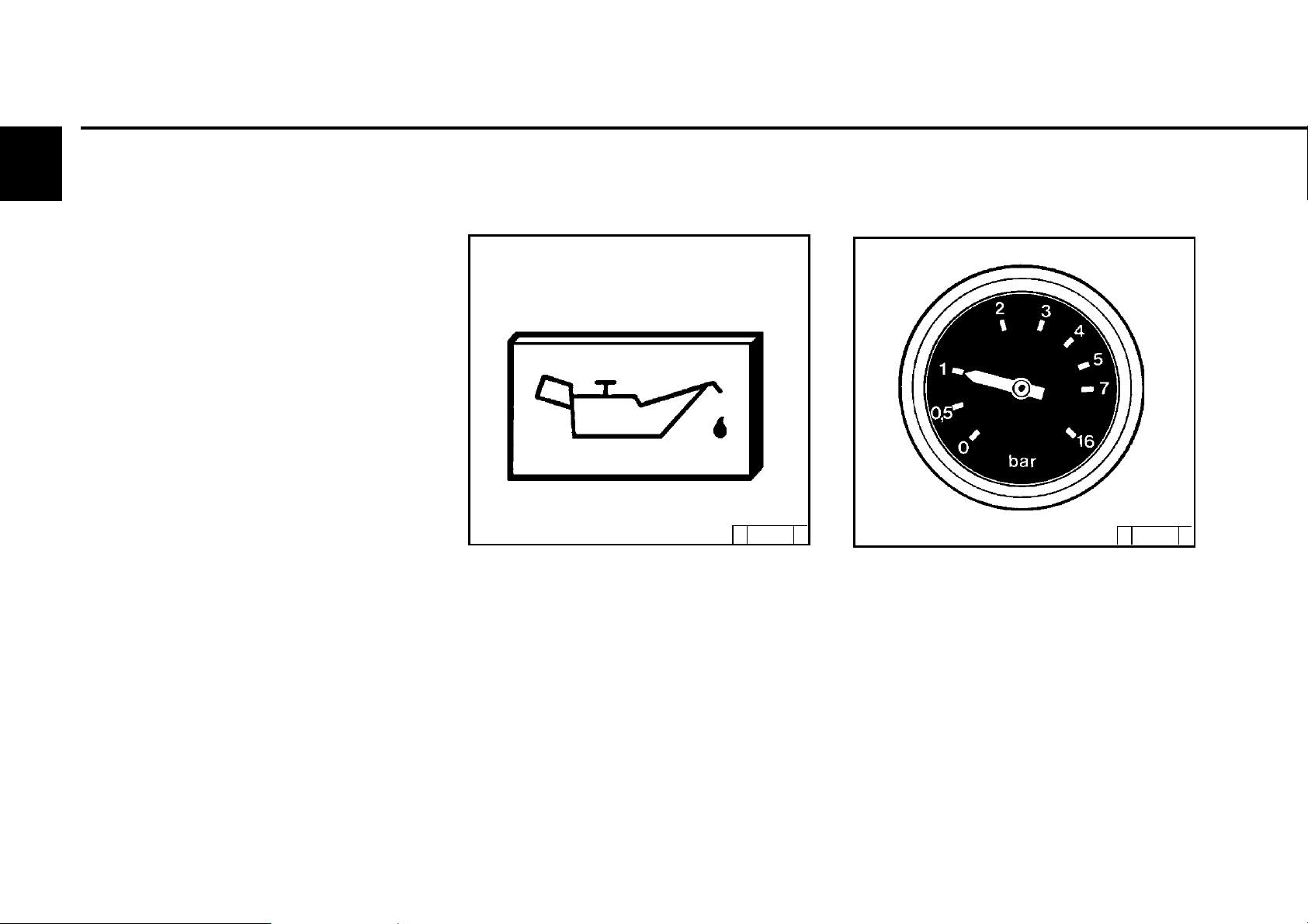
4.2.2 Winter fuel
For the engines TCD 2012/2013 2V and
TCD 2012/2013 4V which are operated
with fuel according to ASTM D 975 1-D/
2-D, adding paraffin is not permissible.
At low ambient temperatures paraffin
discharges can lead to blockages in the fuel
system and cause operating faults. Use winter
fuel at outside temperatures below 0 °C (to
-20 °C) (generally offered by petrol stations
in good time before the cold season begins).
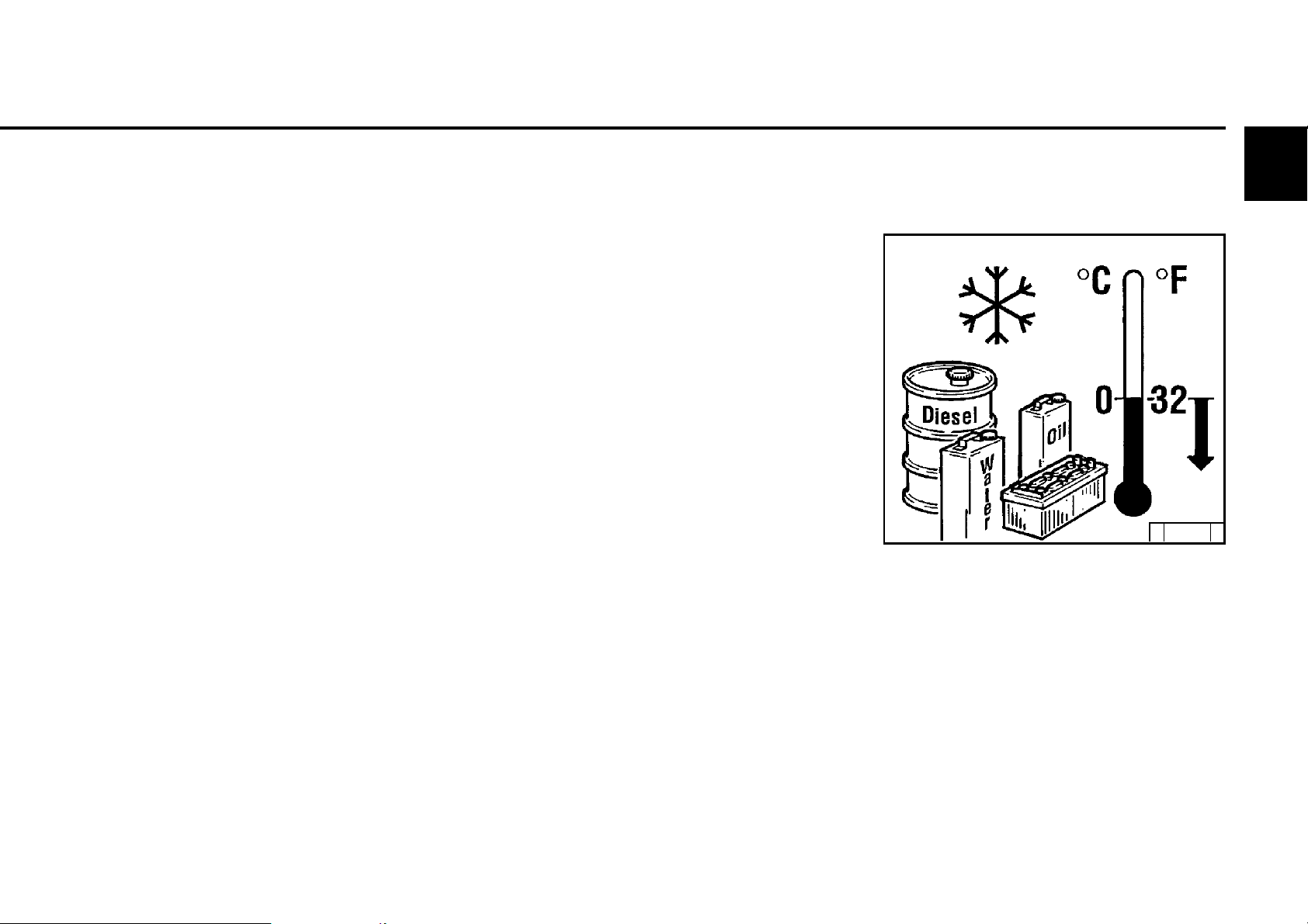
z Paraffin should be added at temperatures
below -20 °C. The mixing ratios required
are as per the diagram on the right.
z Special diesel fuels can be used for arctic
climates to -44 °C.
If it is necessary to use summer diesel fuel
under 0 °C, paraffin can also be added up to
30 % as per the diagram on the right.
Generally, sufficient resistance to cold can
also be achieved by adding a flow ameliorant.
For questions regarding this please contact
your DEUTZ partner.
Diagram key:
I Summer diesel fuel
I I Winter diesel fuel
A Outside temperature
B Paraffin mixing proportion
Only carry out mixing in the tank!
First pour in the necessary
amount of paraffin, then the
diesel fuel. Addition of normal
and super petrol is not
permitted.
4
© 43 923 0
© 2005

Operating substances 4.3 Coolant
4
4.3.1 General
In liquid-cooled engines, the coolant must be
conditioned and monitored otherwise the engine
may incur damage due to:
z corrosion,
z cavitation,
z freezing.
The correct water quality is important for
conditioning the coolant. Basically, clear, clean
water within the following analysis values must
be used:
Analysis values min. max.
ph value at 20 °C 6.5 8.5
Chloride ion content[mg/dm3] - 100
Sulfate ion content[mg/dm3] - 100
The water must be treated if it deviates from the
analysis values.
z pH value too low:
Addition of diluted caustic soda or caustic
potash solution. Small sample mixtures are
advisable.
z Total hardness too high:
Mix with softened water
z Total hardness or carbon hardness too low:
Mix with harder water
z Chloride and / or sulfate too high:
Mix with softened water
*2
Softened water is a distilled water, pH neutral
condensate or water treated with ion
exchangers.
*2
*3
*2
Total hardness *1[°dGH] 3 12
1
*
carbonate hardness proportion of total
hardness min 3 dGH.
Water quality data are obtainable from the
local waterworks.
A test case can be requested from DEUTZ
Service (order no. 1213 0382) for checking
your water quality.
© 2005
*3
Harder water is available in most cases in the
form of drinking water (city water).

4.3 Coolant Operating substances
4.3.2 Coolant preparation
The coolant for liquid-cooled DEUTZ compact
engines is conditioned by mixing an antifreeze
with ethylene-glycol-based corrosion protection
inhibitors into the water.
The best results are achieved with DEUTZ cooling
system preservatives:
Container Order no.
5 liter container 0101 1490
20 liter container 0101 6416
210 liter container 1221 1500
This cooling system is free from nitrite,
amine, phosphate and adapted to the materials in
our engines. Order from your DEUTZ Service
f the DEUTZ cooling system preservative is not
available, a coolant according to T 4-1-5 can be
used.
Coolants of product group A or B respectively can
be mixed.
Coolants of product group A may not be mixed
with coolants of product group B.
4
The cooling system must be monitored regularly,
see 5.1. This includes checking the concentration
of the cooling system preservative, as well as
inspecting the coolant level.
The inspection of the concentration of cooling
system preservative can be carried out with
standard testing devices (e.g. refractometer).
Cooling system W ater Cold protection
preservative percentage up to
percentage
min. 35 % 65% -22 °C
40 % 60% -28 °C
max. 45 % 55% -35 °C
At temperatures below -35°C, please consult
your responsible DEUTZ Service.
It is possible to use other cooling system
preservatives (e.g. chemical corrosion
preservatives) in exceptional cases. Consult
DEUTZ Service.
The mixing of nitrite based cooling
system preservatives with aminebased agents forms nitrosamines
which are hazardous to the health!
Cooling system preservatives must be disposed
of in an environmentally friendly manner.
© 2005

5.1 Maintenance schedule
5.2 Maintenance diagram
5.3 Maintenance work carried out
Maintenance
5
© 2005

Maintenance 5.1 Maintenance schedule
5
check= z set= clean=L renew=
⇓ check 2x daily before or during the 1st trial run, during the running-in phase or
when commissioning new and overhauled engines
⇓ every 10 oh or daily
in operating hours (oh) every year(s)
E10 E20 E30 E40 E45 E50 E60 E70
500 1,000 1,500 3,000 6,000 12,000 1 2
zz
1)
z
zz
zzz
zz
zz L
zz
zz
zzz
zz
zz
zz
1)
z
z
z
Activity
Lube oil level, if necessary re-fill 6.1.2
Lube oil (oil change intervals depending on engine application and oil quality), see TR 0199-99-3002
Oil filter cartridge 6.1.3
Fuel filter cartridge 6.2.1
Electronic injector check via EMR3
Fuel filter insert1) (fuel pre-filter) 4.2
Coolant (additive concentration) 4.3.1/2/3
Coolant level –
Intake air filter
Charge air cooler (drain lube oil/condensation)
Check function of heating plug / heating flange
Battery and cable connections 6.7.1
Engine monitoring, warning system
Valve clearance / contol piston clearance (exhaust gas return) 6.6.1
V-belt (re-tighten if necessary) 6.5.1
V-rib belt/tension pulley (renew when wear limit reached) 6.5.1
Crankcase pressure bleed valve
Engine tightness (visual inspection for leaks) –
Engine mounting (renew in case of damage) 9.2
Fastenings, hose connections / clamps
General overhaul
(if available, maintenance as per maintenance display)
Industrial engines
The engine maintenance times given are maximum permissible job
times. Depending on the usage circumstances, shorter maintenance
times may be necessary. Observe the instruction manual of the
equipment manufacturer.
# Maintenance only to be carried out by authorised service personnel
Section
6.1.1/ 6.1.2
#
6.4.3 /6.4.4
2)
3.3
#
#
–
#, 5.1.1
1)
The maintenance interval must be halved for contaminated fuel or poor quality fuel.
2)
If the warning system (light/siren) is activated, the fuel pre-filter must be emptied immediately.
© 2005

5.1 Maintenance schedule Maintenance
check= z set= clean= L renew=
max. permissible job times in operating hours (oh) every
check 2x daily before or during the 1st trial run, during the running-in phase or
⇓
when commissioning new and overhauled engines
⇓ every 10 oh or daily
in operating hours (oh) every year(s)
E10 E30 E40 E70
500 5,000 12,000 1 2
z
z L
z L
Lube oil
Injector
Charge air cooler (drain lube oil/condensation)
Charge air cooler inlet surface (clean if necessary) #
Crankcase bleeding valve
Exhaust turbocharger compressor outlet -
Activity
(oil change intervals depending on engine application and oil quality), see TR 0199-99-3002
Enhancements or modifications
for engines with EPA acceptance
The engine maintenance times given are maximum
permissible job times. Depending on the usage
circumstances, shorter maintenance times may be
necessary. Observe the instruction manual of the
equipment manufacturer.
# Maintenance only to be carried out by
authorised service personnel
5
Section
6.1.1/ 6.1.2
#
#
#
© 2005

5.1 Maintenance schedule Maintenance
5.1.1 Standard maintenance schedule
Intervals Deutz maintenance Activity Execution by:
at/ after
50 oh E 10 after commissioning and E 50-E 70 authorised specialists
10 oh or daily E 20 daily inspection round the user / authorised specialists
500 oh E 30 inspection authorised specialists
100 0 oh E 40 intermediate overhaul authorised specialists
150 0 oh E 45 extended intermediate overhaul authorised specialists
3 000 oh E 50 partial overhaul authorised specialists
5 000 oh (EPA) E 60 extended partial overhaul authorised specialists
6 000 oh E 60 extended partial overhaul authorised specialists
12 000 oh
*)
and service schedules
E 70 general overhaul authorised specialists
5
*) approximate value, depends on the type of engine application and/or regular engine maintenance.
Please contact your responsible DEUTZ Service partner.
© 2005

5
Maintenance 5.2 Maintenance diagram
The maintenance diagram shown on this
page is supplied with every engine in selfadhesive form. It should be stuck onto a well
visible location on the engine or equipment.
Check that this is the case!
If not, request a replacement from your engine
or equipment supplier!
The maintenance schedule is decisive for
standard maintenance, see 5.1.
© 2005
All maintenance work should
only be carried out when the
engine is not running.

5.3 Maintenance work carried out Maintenance
Op. hrs.
50-150
125
375
625
875
1125
1375
1625
1875
*
Date
Signature / stamp Op. hrs. Date
-
250
500
750
1000
1250
1500
1750
2000
Signature / stamp
5
2115
2375
* after commissioning new and overhauled engines
The maintenance work carried out methodically can be recorded in the table and confirmed.
2250
2500
2750
© 2005

Maintenance 5.3 Maintenance work carried out
5
Op. hrs.
2875
3125
3375
3625
3875
4125
4375
4625
4875
Date Signature / stamp
Op. hrs. Signature / stamp
3000
3250
3500
3750
4000
4250
4500
4750
5000
Date
5125
5375
5625
The maintenance work carried out methodically can be recorded in the table and confirmed.
© 2005
5250
5500
5750

5.3 Maintenance work carried out Maintenance
Op. hrs.
5875
6125
6375
6625
6875
7125
7375
7625
7825
Date
Signature / stamp Op. hrs. Date
6000
6250
6500
6750
7000
7250
7500
7750
8000
Signature / stamp
5
8125
8375
8625
The maintenance work carried out methodically can be recorded in the table and confirmed.
8250
8500
8750
© 2005

Maintenance 5.3 Maintenance work carried out
5
Op. hrs.
8875
9125
9375
9625
9875
10125
10375
10625
10875
Date Signature / stamp
Op. hrs. Signature / stamp
9000
9250
9500
9750
10000
10250
10500
10750
11000
Date
11125
11375
11625
The maintenance work carried out methodically can be recorded in the table and confirmed.
© 2005
11250
11500
11750

Care and maintenance work
6.1Lubrication system
6.2Fuel system
6.3Cooling system
6.4Combustion air filter
6.5Belt drive
6.6Setting work
6.7Add-on parts
6
© 2005

Care and maintenance work 6.1 Lubrication system
6
6.1.1 Oil change intervals
z The oil change times depend on the engine
application and the quality of the lube oil.
z If the oil change times are not reached
within a year, the oil change should be
carried out at least 1x yearly.
z The following conditions apply for the table
– Sulphur content max. 0.5 % of weight
for diesel fuel.
– Constant ambient temperature -10 °C
(+14 °F)
z For fuels
– with sulphur content > 0.5 to 1%
or
– Constant ambient temperatures < -10 °C
(+14 °F)
z For fuels with a sulphur content higher
than 1% ask your responsible
service representative.
z If the lube oil change intervals are planned
in terms of operating hours, the lube oil
change intervals for installed engines
6.1.1.1 apply.
Carry out oil changes on warm engine when the
engine is not running (lube oil temperature < 80 °C).
© 2005

6.1 Lubrication system Care and maintenance work
6.1.1.1 Lube oil change intervals for installed engines
Lube oil quality
Deutz lube oil quality class DQC I-02 DQC II-05 DQC III-05 DQC iV-05
ACEA specification E2-96 E3-96/E5-02/E07-04 E4-99/E6-04 E4-99/E6-04
see chap 6.1.1.3 only fully synthetic
API specification CF/CF-4 CG-4/CH-4/ CI-4 - -
worldwide specification - DHD-1 - -
special DEUTZ release list - - see chap 4.1.2.1 -
Standard lubricant code designation EO... EO...C - -
for building machines and building vehicles EO...A, EO...B
Engine Engine version Lube oil change intervals in oh
series
6
TCD 2012 Crankcase ventilation:
L04/06 2V open - 500 500 500
TCD 2013 Crankcase ventilation:
L04/06 2V open - 500 500 500
© 2005

Care and maintenance work 6.1 Lubrication system
6
6.1.2 Checking oil level,
changing engine oil
6.1.2.1 Checking oil level
© 25 729 0
z Position the engine or vehicle so as to be level.
– Engine warm:
Switch off the engine, wait for 5 minutes and
check the oil level.
– Engine cold:
Check oil level.
z Extract oil dipstick.
z Wipe with a fibre-free, clean cloth.
z Insert until it stops and extract again.
z Check oil level and re-fill to "MAX" if necessary.
– If the oil level lies just above the "MIN"
line marking, re-filling is necessary.
© 2005
The oil level may not fall short of the "MIN“ line
marking.
6.1.2.2Changing engine oil
© 26 022 0
z Warm up the engine.
z Position the engine or vehicle so as to be level.
– Lube oil temperature approx. 80 °C.
z Switch off engine.
z Position oil drip cup under the engine.
z Unscrew oil drain screw.
© 26 023 0
z Drain off oil.
z Screw in oil drain screw with new sealing ring
and tighten. (For tightening torque
see 9.2).
z Fill lube oil
– For quality / viscosity data see 4.1.
– For filling quantities, see 9.1
z Check oil level, see 6.1.2.1
Caution when draining hot oil:
danger of scalding!
Collect the used oil, do not allow to
seep into floor! Dispose of
according to instructions!

6.1 Lubrication system Care and maintenance work
6.1.3 Changing oil filter
© 25 880 0
z When anti-rotation lock is installed:
Loosen clamping screws and remove
tightening clamps from below.
z Loosen lube oil filter cartridge with standard
tool and unscrew.
z Collect any oil which may run out.
© 25 881 0
z Clean the sealing surface of the filter support
for any dirt there may be.
z Lightly oil the rubber seal of the new lube oil
cartridge.
z Screw on the cartridge by hand until the seal
makes contact.
6
© 25 882 0
z Tighten the lube oil filter cartridge with a three-
quarter turn (about 10 Nm).
z Check the seal of the lube oil cartridge for
tightness.
z Check oil level, see 6.1.2.
Careful with hot oil:
danger of scalding!
© 2005

Care and maintenance work 6.1 Lubrication system
6
6.1.4 Cleaning / changing
oil filter (cup)
© 30 0 74 1
z Switch off engine.
z Loosen lube oil filter cover 1 with two or three
turns and wait for 30 seconds.
z Unscrew lube oil filter cover 1 with paper filter
cartridge 5 in anti-clockwise direction.
z Carefully loosen paper filter cartridge 5 from
the guide 4, which is inserted in the housing 3,
from above.
© 43 937 0 © 300 74 0
z Collect any lube oil which may run out.
z Crease the paper filter cartridge 5 in the
collection vessel slightly at the side until the
cartridge is released from the clip 6.
z Clean the sealing surface of the filter support
and the lube oil filter cover 1 as well as the guide
4 of any dirt there may be
z Change the round sealing ring 2 and lightly oil.
z Press new paper filter cartridge 5 into the clip
6 and insert carefully in the guide 4 together.
z Screw the lube oil filter cover 1 tight in clockwise
direction (25 Nm).
z Start the engine.
z Check lube oil filter assembly for leaks.
z Check engine oil level and top up if necessary.
© 2005
Careful with hot oil:
Danger of scalding
Dispose of used oil in an
environmentally friendly way.

6.1 Lubrication system Care and maintenance work
6
© 2005

Care and maintenance work 6.2 Fuel system
6
Regulations for working on the fuel system
Engine must be switched off!
Smoking and naked lights
prohibited!
No injection/high pressure pipes
may ever be disconnected
when the engine is running.
Caution when handling hot fuel!
Pay attention to absolute cleanliness when
refueling and working on the fuel system!
Clean the vicinity of the components
concerned carefully. Blow damp areas dry
with compressed air.
Observe the safety regulations and national
regulations for handling fuels.
Dispose of leaked fuel and filter elements
according to regulations. Do not allow fuel to
seep into the ground.
After working on the fuel system, bleed it,
conduct a test run and check for leaks.
Additional venting of the fuel system by
a 5 minute trial run in idle or low load is
absolutely essential.
Additional regulations for DEUTZ Common
Rail Systems
Danger to life! Never work on
the fuel system with the engine
running. The system is under
high pressure!
Do not stand near to a leak in the
high pressure system because fuel jet can
cause severe injury! After switching off the
engine, wait 30 seconds before working on
the fuel system. In the event of leaks in the fuel
system contact your DEUTZ Service
immediately!
Cleanliness hints and measures for
handling DEUTZ Common Rail Systems
Pay attention to extreme cleanliness due to
the high-precision technology!
The fuel system must be tight and closed.
Inspect visually for leaks/damage in the
system.
Clean the engine and engine compartment
thoroughly and dry before starting work.
Cover engine compartment areas from which
dirt could be loosened with fresh, clean foil.
Work on the fuel system may only be carried
out in an absolutely clean environment. Air
contamination such as dirt, dust, moisture
etc. must be avoided.
© 2005

6.2 Fuel system Care and maintenance work
6.2.1 Changing fuel filter
© 25 880 0
zClose fuel stopcock.
zLoosen fuel filter cartridge with standard tool
and unscrew.
zCollect any fuel which may run out.
zClean the sealing surface of the filter support
for any dirt there may be.
zLightly oil the rubber seal of the filter support.
© 25 881 0
zLightly oil the fuel filter cartridge or wet with
diesel fuel.
zScrew on the cartridge by hand until the seal
makes contact.
6
© 25 882 0
zTighten the fuel filter cartridge with a three-
quarter turn (10 Nm).
zOpen fuel stopcock.
zCheck for tightness.
No open fire when working on
the fuel system! Do not smoke!
Pay attention to cleanliness as
the fuel system (rail) is very
sensitive!!!
Venting of the fuel system is
necessary, see chapter 6.2.3.
© 2005

Care and maintenance work 6.2 Fuel system
6
6.2.2 Cleaning / changing fuel
filter (cup)
© 30 074 0
z Switch off engine.
z Loosen fuel filter cover 1 with two or three
turns and wait for 30 seconds.
z Unscrew fuel filter cover 1 with paper filter
cartridge 5 in anti-clockwise direction.
z Carefully loosen paper filter cartridge 5 from
the guide 4, which is inserted in the housing 3,
from above.
© 2005
© 43 937 0
z Collect any fuel which may run out.
z Slightly bend paper filter cartridge 5 sideways
in the collecting vessel until the cartridge is
loosened from clamp 6.
z Clean the sealing surface of the filter support
and the fuel filter cover 1 as well as the guide
4 of any dirt there may be.
© 43 938 0
z Change the round sealing ring 2 and lightly oil.
z Press new paper filter cartridge 5 into the clip
6 and insert carefully in the guide 4 together.
z Tighten the fuel filter cover 1 in clockwise
direction (25 Nm).
z Start the engine.
z Check fuel filter attachment for tightness.
Only work on the fuel system
when the engine is switched off.
Wait at least 30 seconds.
No open fire! Do not smoke!
Dispose of used fuel in an environmentally friendly manner.
Venting of the fuel system is necessary, see chapter 6.2.3.

6.2 Fuel system Care and maintenance work
6.2.3 Fuel pre-filter, changing /
bleeding filter insert
© 43 848 1
Filter change:
z Close fuel stopcock (for high tanks).
z Position fuel collecting vessel beneath fuel
pre-filter.
z Loosen drain cock (7) and drain water + fuel
completely.
z Unscrew filter cartridge (5) together with
water collecting vessel (8) in anti-clockwise
direction and remove.
z Loosen water collecting vessel (8) from old
filter cartridge (5) in anti-clockwise direction
and remove.
z Empty remaining fuel into the fuel collecting
vessel and clean water collecting vessel (8).
z Screw water collecting vessel (8) onto the
new filter cartridge (5) in clockwise direction.
z Clean any dirt from the sealing surface of the
new filter cartridge (5) and the reverse side
of the filter head
z Wet the sealing surfaces of the filter cartridge
(5) slightly with fuel and screw back onto the
filter head in clockwise direction (17-18 Nm).
z Open the fuel stopcock and bleed the system
(see "Bleeding fuel system").
z Dispose of collected fuel and old filter cartridge
(5) properly.
Bleeding fuel system:
z Unlock the bayonet plug of the fuel hand
pump (3) by pressing and turning
anti-clockwise at the same time. The pump
plunger is now pushed out through the spring.
Turn the shutdown lever of the ther-
mostat valve (4) by approx. 45° in
clockwise direction until it is felt to
engage.
z Pump until a very strong resistance is felt and
pumping becomes very slow.
z Now carry on pumping a few more times (the
return pipe must be filled).
z Start the engine and run for about 5 minutes in
idle or low load. Check the pre-filter for leaks.
z Perform some more pumping movements.
(The return line must be filled).
z Turn the shutdown lever of the thermostat
valve (4) by approx. 45° in anti-clockwise
direction until it is felt to engage.
z Lock the bayonet plug of the fuel hand pump
(3) by pressing and turning clockwise at the
same time.
1 Fuel supply to pump
2 Fuel return from control block FCU
Fuel Control Unit)
(
3 Fuel hand pump with bayonet
plug for locking and unlocking
4 Thermostat valve with shutdown lever
5 Filter cartridge
6 Connection facility for electrical
water level sensor
7 Drain cock
8 Water collecting vessel (bowl)
9 Fuel inlet from fuel tank
10 Fuel return to fuel tank
A Connection for electr. warning lamp / siren
Only work on the fuel system
when the engine is switched off.
No open fire! Do not smoke!
Dispose of used fuel in an environmentally friendly manner.
6
© 2005

Care and maintenance work 6.3 Cooling system
6
6.3.1 Cleaning intervals
z The cooling system soiling depends on thetype
of engine application.
z The risk of soiling is increased by oil and fuel
residues on the engine. Therefore pay particular
attention to tightness when operating under
high dust exposure.
z Increased soiling occurs, for example, during:
- Building site application from high dust content
of air.
- Harvesting application from high proportion of
chaff and chopped straw, for example, in the
area of the work machine.
z Due to the various application conditions, the
cleaning intervals must be defined according
to each case. Therefore, the cleaning intervals
given in the table below can be used as
guidelines.
Checking or
cleaning intervals
Guideline oh
2000 Ships, electronic units in
1000 Vehicles on paved roads
500 Tractors, fork lift trucks, drivable
250 Vehicles on building sites and
125 Agricultural machinery, tractors
© 2005
Engine application
enclosed spaces, pumps
electronic units
unpaved roads, building
machines, compressors, mining
equipment.
with harvesting application.
6.3.2 Cleaning cooling system
© 43 901 0
Cleaning with compressed air
z Blast out the engine with compressed air. Do
not damage any components.
z Rinse out the loosened dirt with a water jet.
© 43 902 0
Cleaning with cold cleaner
z Spray the engine with standard cold cleaner
and leave to work for approx. 10 minutes.
z Spray the engine clean with an acute water jet
(do not spray the water jet directly at sensitive
engine parts, e.g. generator, cabling, electronic components, fan drive).

6.3 Cooling system Care and maintenance work
© 43 903 0
Cleaning with steam or hot water
z Remove oil and greasy residues with a gentle
jet setting (do not spray directly on sensitive
engine parts, e.g. generator, wiring, electricalcomponents, fan drive).
6
z Warm up the engine so that the water residues
evaporate.
External cooling
z For external coolers: Cleaning as per
specifications of the cooling system manufacturer.
Injection pressure: maximum 100 bar and at a
distance of 1 meter!
© 2005

Care and maintenance work 6.3 Cooling system
6
6.3.3 Emptying cooling system
© 43 839 0
z Open cooler cover.
z Position collecting dish underneath locking
screw 1.
z Remove locking screw 1 on the crankcase.
z Drain off coolant.
z Re-tighten locking screw 1.
z If locking screw 1 is not accessible, the cooling
system can be emptied on the engine oil cooler
(coolant channel).
Caution when draining hot
coolant: danger of scalding!
Collect coolant when draining
off. Dispose of according to
© 2005
instructions!
6.3.4 Filling / bleeding
cooling system
© 39 850 1
z Open cooler cover.
z Loosen locking screw item 1 (chap.6.3.3).
z Pour in coolant until the maximum mark or
the filling limit (system heating valve must
be open, if present).
z Tighten locking screw item 1(chap.6.3.3).
z Close cooler cover.
z Start engine and warm up until the thermostat
opens.
z Switch off engine.
z Check the coolant level with the engine cold
and re-fill if necessary.
z Close cooler cover.
z The cooling system (if constructed under
consideration of our installation guidelines) is
bled automatically after filling.
Never operate the engine
without coolant (not even
briefly).

Care and maintenance work 6.4 Combustion air filter
6.4.1 Cleaning intervals
z The soiling of the combustion air filter de-
pends on the dust content of the air and the
selected filter size. If a high dust exposure
is to be expected, a cyclone separator can
be connected to the combustion air filter.
z The cleaning intervals cannot be generally
defined. They must be defined depending
on each case.
z If dry air filters are used, cleaning should
only be carried out according to the maintenance display or maintenance switch.
z Filter maintenance is required when on the:
- Maintenance display
the red service field 1 is fully visible
when the engine is not running.
- Maintenance switch
the yellow warning light lights up
when the engine is running.
6
© 25 885 1
z After completion of the maintenance work
push the reset button on the maintenance
display. The maintenance display is ready
for operation again.
© 2005

Care and maintenance work 6.4 Combustion air filter
6
6.4.2 Emptying cyclone preseparator
© 25 886 0
z Loosen wing nut 1 and lift housing cover 2.
z Remove the dust container 3 from the base of
the cyclone 4 and empty. Clean foliage, straw
and the like from the cylone base.
z Place the dust container 3 on the base 4 and
tighten the housing cover 2 with wing nut 1.
6.4.3 Cleaning oil bath air filter
© 25 887 1
z Turn off the engine and wait approx. 10 min
until the oil has run out of the filter housing 1.
z Loosen quick fasteners 2 and remove oil pan
3 with filter insert 4, if possible loosen filter
insert on the dividing point with the aid of a
screwdriver. Do not damage rubber seal 5!
z Remove soiled oil and sludge, clean oil pan.
z Clean filter insert 4 in diesel fuel and allow to
drip dry thoroughly.
z In the event of heavy soiling, clean filter hou-
sing 1.
z Visually inspect rubber seals 5 and 6 and
renew if necessary.
z Fill up the oil pan with engine oil up to the oil level
mark (arrow) (for viscosity see 4.1.2).
z Place the oil pan with the filter insert on the filter
housing and close the plugs.
Never fill the dust container with oil, replace
damaged containers!
© 2005
Never clean the filter in petrol!
Dispose of used oil according to
instructions!

6.4 Combustion air filter Care and maintenance work
6.4.4 Dry air filter
Dust discharge valve
© 25 888 1
z Empty the dust discharge valve 1 by squee-
zing the discharge slot in the direction of the
arrow.
z Clean the discharge slot occasionally.
z Remove any stuck on dust residues by squee-
zing the upper area of the valve.
Filter cartridge
© 25 889 0
z Open clamping bracket 1.
z Remove filter hood 2 and pull out filter cartridge 3.
z Clean filter cartridge, renew after a year at the
latest.
z Clean filter cartridge 3.
- Blast out from the inside out with dry compressed air (max. 5 bar), or
- beat out (only in extreme cases). Do not
damage the cartridge, or
- wash according to manufacturer’s specifications.
6
z Check filter cartridge for damage to the filter
paper (shine light through) and damage to the
seal. Exchange if necessary.
z Renew the safety cartridge 4 after 5 filter
maintenances, after 2 years at the latest
(never clean!).
To d o thi s:
- Loosen the hexagonal nut 5 and pull out
the cartridge 4.
- Insert new cartridge, re-mount hexagonal
nut and tighten.
z Insert filter cartridge 3, close hood 2 and
secure clamping bracket 1.
Never clean filter cartridge with
petrol or hot liquids!
© 2005

Care and maintenance work 6.5 Belt drive
6
6.5.1 Checking V-belt
2013 example
© 43 894 0
z Visual inspection of entire length of V-belt for
damages.
z Renew damaged V-belts.
z Check the belt tension of new V-belts after 15
minutes running time.
© 26 261 1
z To check the V-belt tension
- Use a tension measuring device (see 9.3).
- Lower indicator arm 1 into the measuring
device.
- Lay the guide 3 between two belt pulleys
on the V-belt 2. The stop should lie sideways.
- Press the button 4 at right angles to the
V-belt 2 steadily, until the spring is heard or felt
to unlock.
- Carefully lift the measuring device, without
altering the position of the indicator arm 1.
- Read off the measured values on the in
tersection (arrow), scale 5 and the indicator
arm 1. For setting values see 9.1.
- If necessary, re-tighten and repeat
measurement.
© 2005
Only test / tighten / change V-belts
when the engine is not running.
If necessary, re-mount V-rib belt
guard.

6.5 Belt drive Care and maintenance work
6.5.2 Changing V-rib belt
© 31 814 4
z Push tension roller 1 with ratchet 3 in direction
of arrow until locking pin 4 can be fixed in the
mounting hole. V-rib belt 2 is now tension-free.
z First pull the V-rib belt 2 from the smallest roller or
from the tension roller.
z Fit new V-rib belt 2.
z Hold ratchet 3 in the opposite direction to the
arrow and remove pin 4.
z Loosen the tension pulley in the opposite
direction to the arrow until the V-rib belt is tight,
at the same time checking that the V-rib belt is
positioned correctly in its guides.
6.5.3 Checking wear limit
6
of V-rib belt
© 43 851 0
z The wear limit of the V-rib belt is checked as
follows:
z Check the distance between the projection
of the moving tension arm and the contact
with the fixed tensioner housing.
z If the distance "a" is less than 3 mm, the V-rib belt
should be changed.
Only test / tighten / change when
the engine is not running.If neces-
sary, re-mount V-belt guard.
© 2005

Care and maintenance work 6.6 Setting work
6
6.6.1 Checking valve clearance,
setting if necessary
© 43 831 1
z Before setting the valve clearance allow the
engine to cool down for at least 30 minutes: Oil
temperature below 80 °C.
z Place the turning gear (see chap. 9.3) over the
fastening screws of the belt pulleys.
z Turn over engine until the valve overlap is
achieved, cylinder no. 1.
The cylinders to be set are specified in the
setting schematic, see chap. 6.6.3.
Special tools for valve setting
see chap. 9.3
z Loosen lock nut 1
z Place rotation angle disc and socket wrench
insert 4 on the valve clearance setting screw 2.
z Fix magnet 5 to the rotation angle disc 3.
z Turn the rotation angle disc 3 clockwise to the
stop (rocker arm without clearance) and set
scale to zero.
z Turn the rotation angle disc anti-clockwise until
you reach the specified rotation angle size:
Engine 2012
IN = inlet valve 75°
EX = outlet valve 120°
Engine 2013
IN = inlet valve 90°
EX = outlet valve 150°
© 43 849 0
z Hold rotation angle disc 3 tight against
twisting.
z Tighten the lock nut 1.
z Perform the setting on every cylinder (see
chap. 6.6.3).
© 2005

6.6 Setting work Care and maintenance work
6
© 44 304 0
Valve clearance setting inlet valve
in exhaust gas return line (EGR):
z Loosen lock nut 6.
z Place rotation angle disc 3 with crow's foot
wrench 8 on valve clearance setting screw
7 on the inlet valve.
z Fix magnet 5 to the rotation angle disc 3.
z Turn the rotation angle disc 3 clockwise to the
stop (rocker arm without clearance) and set
scale to zero.
z Turn the rotation angle disc anti-clockwise until
you reach the specified rotation angle size.
Engine 2012
IN = inlet valve 75°
Engine 2013
IN = inlet valve 90°
© 44 305 0
z Hold rotation angle disc 3 tight against twisting.
z Tighten the lock nut 6.
z Perform the setting on every inlet valve (see
chap. 6.6.3)
© 2005

Care and maintenance work 6.6 Setting work
6
6.6.2 Setting control piston
clearance in exhaust gas
recirculation (EGR)
© 43 830 1 © 43 832 0
z After setting the valve clearance, the control
piston clearance should be set as follows:
z Place the turning device over the fastening
screws of the belt pulley.
z Turn engine until reaching the valve overlap,
cylinder no. 1 The cylinders to be set are
specified in the setting diagram, see chap.
6.6.3
z Loosen lock nut 1.
z Place the rotation angle disc and socket wrench
insert on the setting screw 2
z Fix the magnet of the rotation angle disc.
z Turn the rotation angle disc clockwise to the
stop (control piston without clearance) and set
scale to zero.
z Turn the rotation angle disc counter-clockwise
until you reach the specified rotation angle.
Control piston x : 144°
z Tighten the lock nut 1.
z Perform the setting on every control piston
(see chap. 6.6.3)
Special tools for valve setting see chap. 9.3
© 2005

6.6 Setting work Care and maintenance work
6.6.3 Diagram for setting valve /
control piston clearance
Engine TCD 2012/2013 L04 2V
Ignition sequence: 1–3–4–2
Valves Cylinder
overlap 1 3 4 2
set to 4 2 1 3
Valve operlap: Outlet valve not yet closed, inlet
valve starts opening.
At fully open outlet valve, the inlet
valve opens briefly by about 2 mm.
This is not the valve overlap.
6
Engine TCD 2012/2013 L06 2V
Ignition sequence: 1–5–3–6–2–4
Valves Cylinder
overlap 1 5 3 6 2 4
set to 6 2 4 1 5 3
Valve operlap: Outlet valve not yet closed, inlet
valve starts opening.
At fully open outlet valve, the inlet
valve opens briefly by about 2 mm.
This is not the valve overlap.
© 2005

Care and maintenance work 6.7 Add-on parts
6
6.7.1 Battery
6.7.1.1 Checking battery and cable
connections
© 25 895 0
z Keep the battery clean and dry.
z Loosen soiled connection terminals.
z Clean the battery poles (+ and -) and terminals,
and grease with an acid-free and acid-resistant grease.
z Ensure that the terminal connections contact
well when assembling. Tighten the clamping
screws by hand.
6.7.1.2 Checking the acid level
© 24 232 3 © 25 896 0
z Remove sealing caps 1.
z If checking inserts 2 are available:
The liquid level should reach to their bottom.
z Without checking inserts:
The liquid level should reach 10-15 mm above
the upper edge of the plate.
z If necessary, re-fill with distilled water.
z Screw sealing caps back on.
6.7.1.3 Checking acid density
z Measure the acid density of individual cells
with a standard acid testing device.
The measured values (see table overleaf)
indicate the charge status of the battery. The
acid temperature when measuring should be
20 °C if possible.
© 2005

6.7 Add-on parts Care and maintenance work
Acid density
in [kg/ l]
Charge level
6
Normal
1.28
1.20
1.12
Tropics
1.23
1.12
1.08
The gases released by the battery
are explosive! Avoid sparks and
open fire in the vicinity of the
battery! Do not allow acid to get on
skin or clothes!
Wear protective glasses!
Do not place any tools on the
battery!
discharged, charge immediately
well charged
half charged, re-charge
© 2005

Care and maintenance work 6.7 Add-on parts
6
6.7.2 Three-phase current
generator
Notes on three-phase current system:
z Do not interrupt the connections between the
battery, generator and governor when the
engine is running.
z If, however, an engine must be started and
operated without battery, the connection governor / generator is to be separated before
starting.
z Do not swap battery connections.
z Replace defective charging warning light im-
mediately.
z When cleaning engine: Do not spray water/
steam jet directly at generator!
Warm up the engine so that the water residues
evaporate.
z Under no circumstances may the voltage of a
three-phase current system be tested by
tapping against the earth cable.
z When carrying out electrical welding work,
clamp the earth terminal of the welding device
directly to the part to be clamped.
6.7.3 Transportation suspension
© 43 842 0 © 43 841 1
z Only use the correct suspension equipment
for engine transportation. Suspension equipment must be adjustable for the engine centre
of gravity.
z Fastening devices cannot be fixed safely over
the centre of gravity.
z Fastening devices can slip, engine capsizes.
z Short fastening devices cause bending mo-
ments in the suspension. This can damage the
suspension.
z Disconnect battery and three-phase current
generator.
z Remove the control unit.
© 2005
Only use correct suspension
equipment!
Engine can fall.
Danger to life!

6
© 2005

Faults, causes and remedies
7.1 Fault table
7.2 Engine management
7
© 2005

7
Faults, causes and remedies
z Faults are often caused by incorrect operation
or maintenance of the engine.
z For every fault, check whether or not all
operating and maintenance specifications
have been observed.
z A corresponding fault table can be found
overleaf.
z If you cannot recognise the cause of a fault
or cannot remedy a fault yourself, please
contact your DEUTZ Service.
© 2005
Before starting make sure that
there is nobody in the engine/
work machine danger area.
For repairs:
Caution: Separate battery
connection!

7.1 Fault table
Faults Action
Faults, causes and remedies
Engine doesn't start up, or starts up with difficulty
Engine doesn't start up and diagnosis light is blinking Check C
Engines starts up, but runs irregularly or misfires Set S
Engine gets too hot. Temperature warning system is activated Change Ch
Engine lacks power
Engine lacks power and diagnosis light is lit up Clean Cl
Engine doesn't work on all cylinders Fill up F
Engine has no, or too little, oil pressure Lower L
Engine has too high oil consumption Engine electronics E*
Engine smoulders - blue * Identify fault by
- white monitoring the blink
- black code or fault memory
Cause
z
zz
zz
zz
zz zz
zzz
z
zz z
zz z
zz z
z
zz
z
z zzz z
zz
z
Not disconnected (if possible)
Starting limit temperature not reached
Engine shutdown lever is still in stop position (shutdown magnet defective)
Oil level too low
Oil level too high
Engine is tilted too far
Set throttle to halfway (only with mech. regulators)
Air filter soiled / exhaust turbocharger defective
Air filter maintenance switch / display defective
Charge air line leaking
Cool water pump defective (V-rib belt torn or loose)
Charge air cooler soiled
Coolant heat exchanger soiled
V-belt/V-rib belt torn or loose
(fuel pump in belt drive)
Cool air heating / heat short circuit
Battery defective or not charged
Section
Operation
Combustion air
Cooling system
Electrics
7
C
C
C
F
L
C / S
C / S
C / Ch
C
C / Ch
C
C / Cl
C / Cl
C / W
C
C
© 2005
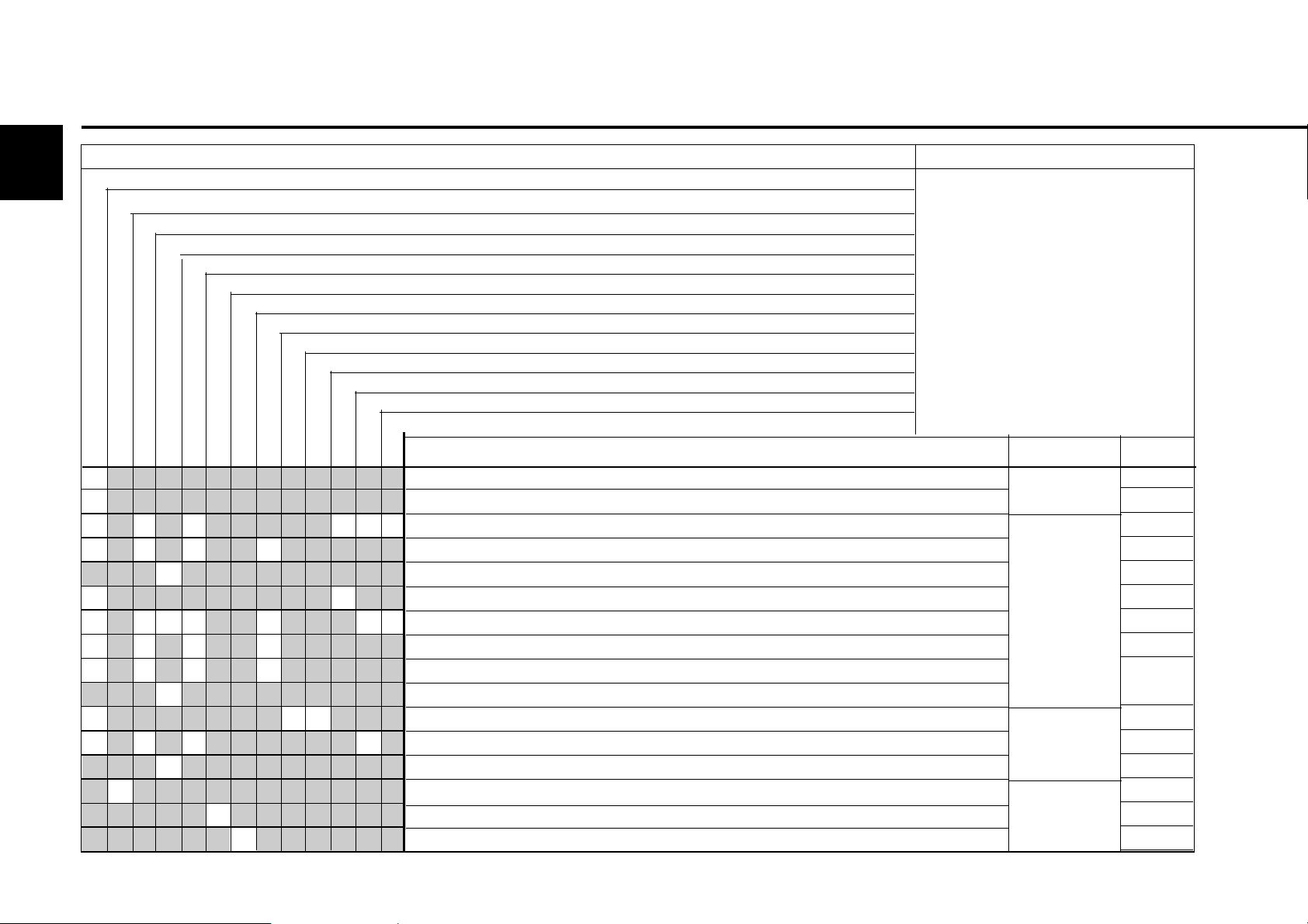
7
Faults, causes and remedies
Faults Action
Engine doesn't start up, or starts up with difficulty Check C
Engine doesn't start up and diagnosis light is blinking Set S
Engines starts up, but runs irregularly or misfires Change Ch
Engine gets too hot. Temperature warning system is activated Clean Cl
Engine lacks power Fill up F
Engine lacks power and diagnosis light is lit up Lower L
Speed changes are possible + diagnostic light is lit up Engine electronics E*
Engine has no, or too little, oil pressure * Identify fault by monitoring the
Engine has too high oil consumption blink code or fault memory
Engine has too high oil consumption
Engine smoulders - blue
- white
- black
Cause Section
7.1 Fault table
z
z
zzz zz
zzz z
z
zz
zzzz z zz
zzz z
zzz z
z
zzz
zzz z
z
z
z
z
© 2005
Starter, circuit cable connections loose or oxidised
Starter defective or pinion doesn't mesh
Valve clearance incorrect
Injection line leaking
Ventilation line blocked (coolant heat exchanger)
Heating plug defective
Injector defective
Air in fuel system
Fuel filter / fuel pre-cleaner soiled
Oil filter defective
Incorrect SAE class or quality of engine lube oil
Fuel quality does not comply with instruction manual
Lack of cooling water
Engine electronics prevent start
Engine electronics reduce power
Engine electronics has detected a system error and activates an equivalent speed
Electrics
Engine
Operating
substance
Electronics
C
C
S
C
C / Cl
C
C / Ch
C / Ch
C/ Cl/
Ch
Ch
Ch
C / Ch
C / Cl
C / E
C / E

7.2 Engine management
Faults, causes and remedies
7.2.1 Engine protection function of
the electronic engine
controller EMR3
Depending on the design of the monitoring
functions, the EMR3 can protect the engine
against damage in certain fault situations by
monitoring compliance with the important limit
values during operation and checking the correct
functioning of the system components. Depending
on the severity of a detected fault, the engine may
continue running with restrictions, whereby the
fault lamp lights steadily or the fault lamp indicates
a serious system fault by flashing. In this case,
the engine must be switched off as soon
as it is safe to do so.
Depending on the engine configuration, the
flashing fault lamp can have the following meaning:
z Request to the operator to shut down
Caution: Failure to heed this will lead to
loss of warranty!
z Autom. shutdown of the engine after a brief
warning time, poss. connected with a start
prevention.
z To cool the engine, forced operation at low
idling speed, poss. with automatic shutdown.
z Start prevention. (see also chap. 3.3)
When the fault is corrected the light
goes out. For some faults it is
necessary to switch off the ignition,
wait for 30 s and then switch the
ignition back on.
7.2.2 Using the diagnosis button
With the diagnosis button (1) the fault at hand can
be read out as a blink code. The diagnosis button
(1) and the fault light (2) can be found on the
vehicle driving stand.
Faults are indicated by a blinking or continuous
illumination of the fault light (2). More precise
information regarding all existing faults can be
read out in the form of a blink code, only when the
engine is not running, in the following manner:
After actuating the diagnosis button (1) for at
least one second, the fault light (2) goes out and
the first fault is, after releasing the key displayed
as a blink code. Analyse the blink code as per the
table on the following page. After the fault blink
code has been displayed the fault light (2) goes
out for five seconds.
Then the next existing fault (i.e. the following one
in the fault memory) can be shown by actuating
the diagnosis button (1) again. If the last existing
fault has been shown, by actuating the diagnosis
button (1) once more the first fault will be shown
again.
7.2.3 Table of fault blink codes
© 43 929 1
The possible blink codes, their meaning and
measures for correcting faults can be found in
the table on the following page. The blink code
values in the first column indicate the number of
preliminary short blink signals (illuminated duration
approx. 0.4 s), the number of subsequent long
blink signals (illuminated duration approx. 0.8 s)
as well as the number of concluding short blink
signals. The code 2-1-4 for the fault "overspeed"
is made up of two short, one long and four short
blink signals, for example. If a fault cannot be
corrected by the measures given in the table
please contact your service representative
responsible.
7
© 2005

Faults, causes and remedies
7.2 Engine management
7
Blinkcode Function / Component Error
Short Long Short
0.4s 0.8s 0.4s
1 2 3 Output to coolant temperature light Signal faulty, Overtemperature control unit
1 2 6 Hand accelerator Signal faulty / implausible
1 2 8 Suction air temperature sensor Signal faulty
1 3 3 Gear oil temperature sensor Signal faulty
1 3 4 Monitoring rail pressure Signal implausible, pressure / pressure deviation outside the permissible range
1 3 5 Output to oil pressure warning lamp Signal faulty, overtemperature control unit
Output to valve Signal faulty, overtemperature control unit
of the fuel measuring unit
1 3 6 Monitoring air filter Air pressure behind filter too low
1 3 7 Output to actuators Short circuit to battery
1 3 8 Output to actuators Short circuit to ground
1 4 2 Output to engine operating lamp Signal faulty, overtemperature control unit
1 4 3 Multi-step switch 1 / 2 / 3 Signal faulty / implausible
1 4 4 Oil temperature sensor Signal faulty / implausible
Monitoring the oil temperature Temperature outside the nominal range
1 4 5 Monitoring override switch Signal implausible
1 4 6 Rail pressure limiting valve Valve open / pressure surge necessary / do not open after pressure surge
1 4 7 Rail pressure sensor Signal faulty, pressure deviation outside the permissible range
© 2005

7.2 Engine management
Faults, causes and remedies
Blinkcode Function / Component Error
Short Long Short
0.4s 0.8s 0.4s
2 1 2 Monitoring camshaft/crankshaft No camshaft signal, no crankshaft signal
2 1 3 Monitoring camshaft/crankshaft Deviation between the camshaft and crankshaft signal
2 1 4 Engine protection: Overspeed/override status implausible
2 1 6 Fuel low pressure sensor Signal faulty
Monitoring fuel low pressure Fuel low pressure outside the nominal range
2 1 9 Output to adjuster exhaust valve engine brake Signal faulty, overtemperature control unit
2 2 2 Input accelerator 1 (PWM) PWM signal faulty
2 2 3 Charge air pressure sensor Signal faulty
Monitoring charge air pressure Charge air pressure outside the nominal range
2 2 4 Oil pressure sensor Signal faulty / implausible
2 2 5 Coolant temperature sensor Signal faulty / implausible in comparison with the oil temperature, CAN signal invalid
2 2 6 Input accelerator 1 (analog) Signal faulty / implausible
2 2 7 Fuel temperature sensor Signal faulty
7
2 2 8 Water level sensor in the fuel filter Signal faulty
Monitoring fuel filter water level Max. water level exceeded
© 2005

Faults, causes and remedies
7.2 Engine management
7
Blinkcode Function / Component Error
Short Long Short
0.4s 0.8s 0.4s
2 3 1 Monitoring oil pressure Pressure outside the nominal range
2 3 2 Monitoring coolant temperature Temperature above the nominal range
2 3 3 Monitoring suction intake air temperature Temperature above the nominal range
2 3 5 Monitoring coolant state Level below the nominal range
2 3 7 Monitoring fuel temperature Temperature outside the nominal range
2 3 8 Output to the fan adjuster 1 / 2 Signal faulty, overtemperature control unit
Monitoring fan speed Speed outside the nominal range
2 4 1 Monitoring combustion Misfiring detected in one or more cylinders
2 6 1 Monitoring output to actuators Relay does not open or opens too late, short-circuit to ground
2 6 3 Output to cold start aid Signal faulty, relay defective, jammed or connected incorrectly, short-circuit
2 7 1 CAN-Bus Timeout of one or more send messages, bus inactive
2 8 2 Sensor supply voltage 1 / 2 / 3 Voltage outside the nominal range
2 9 2 Atmospheric pressure sensor Signal faulty / implausible
© 2005

7.2 Engine management
Faults, causes and remedies
Blinkcode Function / Component Error
Short Long Short
0.4s 0.8s 0.4s
3 1 4 Hydraulic oil temperature sensor Signal faulty
Monitoring hydraulic oil temperature Temperature outside the nominal range
3 1 8 Monitoring battery Voltage outside the nominal range
3 2 8 Output to cold start aid indicator lamp Signal faulty, overtemperature control unit
4 1 4 Output to external EGR actuator Signal faulty
4 1 5 Output to external EGR actuator Signal faulty, overtemperature control unit
4 1 6 Output to external EGR actuator Signal faulty
4 1 7 Oil wear meter Critical time reached
7
© 2005

7
Faults, causes and remedies
Blink code Function / Component Error
Short Long Short
0,4s 0,8s 0,4s
5 1 2 Output to start relay Signal faulty, overtemperature control unit
5 1 3 Output to error lamp Signal faulty, overtemperature control unit
5 1 4 Monitoring terminal 15 No signal detected
5 1 5 Monitoring terminal 50 Permanent signal detected
5 2 1 Speed measurement Implausible drive speed
5 2 8 Output to internal engine brake Signal faulty
All other blink codes: Please contact your service partner
Behavior in case of error signal faulty / implausible: Perform function test on the parts concerned; check wiring and plugs for short-circuits, breaks,
corrosion.
7.2 Engine management
© 2005

Engine corrosion protection
8.1 Corrosion protection

Engine corrosion protection 8.1Corrosion protection
8
8.1 Corrosion protection
If the engine should be shut down for a long
period of time, corrosion protection will be
necessary in order to prevent rust formation.
The measures described here apply for a
shutdown period of up to approx. 6 months.
Before the engine is commissioned again the
corrosion protection should be removed.
z Corrosion protection oils according to
specification:
- MIL-L 21260B
- TL 9150-037/2
- Nato Code C 640 / 642
z Recommended cleaning agent for removal of
corrosion protection:
- Petroleum benzine (hazard class A3)
Protecting engine from corrosion:
z Clean engine (possibly with cold cleaner).
z Warm up the engine and switch off.
z Drain off engine oil, see chapter 6.1.2 and pour
in corrosion protection oil.
z Drain off coolant, see 6.3.3.
z Pour in corrosion protection agent, see above.
z Drain fuel from container (tank).
z Make fuel mixture from 90 % diesel fuel and 10 %
corrosion protection oil and fill up tank.
z Leave the engine running for approx. 10
minutes.
z Switch off engine
z Turn over the engine manually several times.
When turning over with a starter position the
shutdown lever in the Stop position.
z Remove V-belt 4, pack up and store.
© 30 083 1
z Spray the V-belt pulley 5 with corrosion
protection agent.
z Seal intake openings 1 and exhaust openings 3.
z Lightly apply corrosion protection agent to the
coolant nozzle 2 and seal.
z Drain off corrosion protection agent.
Note: Fuel tank/supply line to the engine
should also be sealed, so that the
sensitive rail system is protected
against dirt and dust. Protect the
electronics from moisture/
corrosion.
Removing engine corrosion protection:
z Remove corrosion protection agent from
grooves of V-belt pulley 5.
z Assemble V-rib belt 4 or V-belt, see 6.5.2.
z Remove plugs from intake opening 1, exhaust
opening 3 and coolant inlet/outlet 2.
z Pour in coolant see 6.3.3
z Connect fuel tank / supply line to the engine. Pay
attention to cleanliness here.
z Start up the engine.

9.1 Engine and setting data
9.2 Screw tightening torques
9.3 Tools
Technical data
9
© 2005

9
Technical data 9.1 Engine and setting data
Engine type ----------------------------- TDC 2012 L04 2V ----------------- TDC 2012 L06 2V ---------------------------
Number of cylinders ---------------------------------------- 4 --------------------------------------- 6--------------------------------------Cyl. arrangement ----------------------------------------------------------- In-line --------------------------------------------------------Bore [mm] ------------------------------------------------------------ 101 ---------------------------------------------------------Stroke [mm] ------------------------------------------------------------ 126 ---------------------------------------------------------Total displacement [cm
Compression ratio [ε] ------------------------------------------------------------- 18 -----------------------------------------------------------
Working principle / combustion procedure -------------------- Four stroke diesel with charging and direct injection ---------------------------------Charge air cooler --------------------------------- without/with ------------------------------ with -----------------------------------Charge air cooler temperature outlet
at rated power [°C] ------------------------------------------------------------- 50 -----------------------------------------------------------
Direction of rotation ----------------------------------------------------- rotation to left ---------------------------------------------------Injection system
Deutz Common Rail (DCR) --------------------------------- DCR + PLD ------------------------------ DCR -----------------------------------Pump Line Nozzle (PLD)
Weight TDC 2012 without cooling system
according to DIN 70020-A [approx.kg] --------------------------------------- 410 ------------------------------------ 530 ------------------------------------Engine performance according to ISO 3046 [kW] -------------------------------------------------------------
Max. nominal speed [1/min] ----------------------------------------------------------- 2400 --------------------------------------------------------Valve clearance inlet/ exhaust, see 6.6.1 [mm] ----------------------------------------- 0.3/0.5
Setting with special tool
Ignition pressure [bar] ------------------------------------------------------------ 160 ---------------------------------------------------------Start of pumping [°KW before TDC] ------------------------------------------------------------Engine ignition sequence ------------------------------------ 1-3-4-2 ---------------------------- 1-5-3-6-2-4 ------------------------------V-belt tension ------------------------------------------------ pre-tighten/re-tighten ----------------------------------------------Generator [N] ----------------------------------------------------- 650 / 400
Fuel pump - coolant pump [N] ------------------------------------------------------ 650 / 400
V-rib belt tension: ------------------------------------------- Spring-loaded tension pulley ------------------------------------------
3
] -------------------------------------- 4038 ---------------------------------- 6067 ------------------------------------
1
). -----------------------------------------------------------
+0.1/
angle degree 75/120 ----------------------------------------
1
). -----------------------------------------------------------
± 50
. ----------------------------------------------------
± 50
. ----------------------------------------------------
1)
Engine power, speed and start of pumping, among other things, are stamped on the engine company plate, see also 2.1.
2)
The V-rib belt has a spring-loaded tension pulley which tightens automatically and is not re-tightened: see ch. 6.5.2
© 2005

9.1 Engine and setting data Technical data
Engine type ----------------------------- TDC 2012 L04 2V -----------------TDC 2012 L06 2V ---------------------------
Cooling ----------------------------------------- Liquid-cooled / cooling system protection --------------------------Coolant quantity
(only engine content without cooler)[approx.ltr.] --------------------------------------- 5.6 ------------------------------------- 7.3 -------------------------------------
Permissible continuous coolant temperature engine outlet [°C ] --------------------------------------------------------------
max.110 ------------------------------------------------------Temperature difference between
Coolant inlet/outlet [°C] ----------------------------------------------------------- 4 to 8 --------------------------------------------------------Start of thermostat opening at [°C] ------------------------------------------------------------- 86 ----------------------------------------------------------Thermostat fully open at [°C] ------------------------------------------------------------ 102 ---------------------------------------------------------Coolant pre-heating -------------------------------------------------------------(4. ------------------------------------------------------------
Lubrication ----------------------------------------------- Forced feed lubrication --------------------------------------------Oil SAE ------------------------------------------------------ see chap. 4 ---------------------------------------------------Maximum oil temperature in oil tray [°C] ------------------------------------------------------------ 125 ---------------------------------------------------------Minimum oil pressure in warm state (114 °C)
and low idling [bar] ------------------------------------------------------------ 0,8 ----------------------------------------------------------Initial oil filling quantity without filter max. [approx.ltr.] -------------------------------------- 15
min. [approx.ltr.] -------------------------------------12.5
Initial oil filling quantity with filter max. [approx.ltr.] ------------------------------------- 15.5
min. [approx.ltr.] -------------------------------------- 13
3)
. ---------------------------------- 26 3). ------------------------------------
3)
. -------------------------------- 23.53). -----------------------------------
3)
. -------------------------------- 26.53). -----------------------------------
3)
. ----------------------------------- 24 3). ------------------------------------
9
3)
Approximate values can vary depending on version. The upper oil measurement marking is always decisive.
4)
Only necessary for winter operation, see 3.5.1.
--------------------
© 2005

9
Technical data 9.1 Engine and setting data
Engine type ----------------------------- TDC 2013 L04 2V ----------------- TDC 2013 L06 2V ---------------------------
Number of cylinders ---------------------------------------- 4 --------------------------------------- 6--------------------------------------Cyl. arrangement ----------------------------------------------------------- In-line --------------------------------------------------------Bore [mm] ------------------------------------------------------------ 108 ---------------------------------------------------------Stroke [mm] ------------------------------------------------------------ 130 ---------------------------------------------------------Total displacement [cm
Compression ratio [ε] ------------------------------------------------------------- 18 -----------------------------------------------------------
Working principle / combustion procedure -------------------- Four stroke diesel with charging and direct injection ---------------------------------Charge air cooler ----------- without/with ------------------------------------------------------------------- without/with --------Charge air cooler temperature outlet
at rated power [°C] ------------------------------------------------------------- 50 -----------------------------------------------------------
Direction of rotation ----------------------------------------------------- rotation to left ---------------------------------------------------Injection system
Deutz Common Rail (DCR) [bar] ---------------------------------- DCR+PLD ------------------------------- DCR ------------------------------------
Pump Line Nozzle (PLD)
Weight TDC 2013 without cooling system
according to DIN 70020-A [approx.kg] --------------------------------------- 450 ------------------------------------ 590 ------------------------------------Engine performance according to ISO 3046 [kW] ------------------------------------------------------------Max. nominal speed [1/min] ----------------------------------------------------------- 2300 --------------------------------------------------------Valve clearance inlet / exhaust, see 6.6.1 [mm] ----------------------------------------- 0.4/0.6
Setting with special tool
Ignition pressure [bar] ------------------------------------------------------------ 160 ---------------------------------------------------------Start of pumping [°KW before TDC] ------------------------------------------------------------Engine ignition sequence ------------------------------------ 1-3-4-2 ---------------------------- 1-5-3-6-2-4 ------------------------------V-belt tension:
Generator [N] ----------------------------------------------------- 550 / 300
Fuel pump - coolant pump [N] ------------------------------------------------------ 550 / 300
Compressor [N] ------------------------------------------------------ 650 / 400
V-rib belt tension: ------------------------------------------- Spring-loaded tension pulley ------------------------------------------
3
] -------------------------------------- 4761 ---------------------------------- 7142 ------------------------------------
1
). -----------------------------------------------------------
+0.1/
/ angle degree 90/150 ---------------------------------------
1
). -----------------------------------------------------------
± 50
. ----------------------------------------------------
± 50
. ----------------------------------------------------
± 50
. ----------------------------------------------------
1)
Engine power, speed and start of pumping, among other things, are stamped on the engine company plate, see also 2.1.
2)
The V-rib belt has a spring-loaded tension pulley which tightens automatically and is not re-tightened: see ch. 6.5.2
© 2005

9.1 Engine and setting data Technical data
Engine type ----------------------------- TDC 2013 L04 2V ----------------- TDC 2013 L06 2V ---------------------------
Cooling ----------------------------------------- Liquid-cooled / cooling system protection --------------------------Coolant quantity
(only engine content without cooler)[approx.ltr.] --------------------------------------- 7.2 ------------------------------------- 9.8 -------------------------------------
Permissible continuous coolant temperature engine outlet [°C] --------------------------------------------------------------
max.105 ------------------------------------------------------Temperature difference between
Coolant inlet/outlet [°C] ----------------------------------------------------------- 4 to 8 --------------------------------------------------------Start of thermostat opening at [°C] ------------------------------------------------------------- 86 ----------------------------------------------------------Thermostat fully open at [°C] ------------------------------------------------------------ 102 ---------------------------------------------------------Coolant pre-heating -------------------------------------------------------------
(4
. ------------------------------------------------------------
Lubrication ----------------------------------------------- Forced feed lubrication --------------------------------------------Oil SAE ------------------------------------------------------ see chap. 4 ----------------------------------------------------Maximum oil temperature in oil tray [°C] ------------------------------------------------------------ 125 ---------------------------------------------------------Minimum oil pressure in warm state (114 °C)
and low idling [bar] ------------------------------------------------------------ 0.8 -----------------------------------------------------------
3)
Initial oil filling quantity without filter max. [approx.ltr.] -------------------------------------- 15
min. [approx.ltr.] -------------------------------------12.5
Initial oil filling quantity with filter max. [approx.ltr.] ------------------------------------- 15.5
min. [approx.ltr.] -------------------------------------- 13
. ---------------------------------- 26 3). ------------------------------------
3)
. -------------------------------- 23.53). -----------------------------------
3)
. -------------------------------- 26.53). -----------------------------------
3)
. ----------------------------------- 24 3). ------------------------------------
9
3)
Approximate values can vary depending on version. The upper oil measurement marking is always decisive.
4)
Only necessary for winter operation, see 3.5.1.
© 2005

9
Technical data 9.2 Screw tightening torques
Installation Pre-tightening Re-tightening Total Comments
[Nm] 1st step 2nd step 3rd step 4th step
Cylinder head cover – – – – – 9 ± 1 Nm M6
Lock nut Valves – – – – – 20 ± 2 Nm Nut with inner square
Front face mounting foot – – – – – 280 Nm M16 x 85 –10.9
– – – – – 280 Nm M16 x 40 –10.9
Oil drain screw aluminium tray – – – – – 55 Nm M 18x 1.5 with Cu ring
Oil drain screw sheet metal oil tray
© 2005
– – – – – 55 Nm M 18x 1.5 with Cu ring
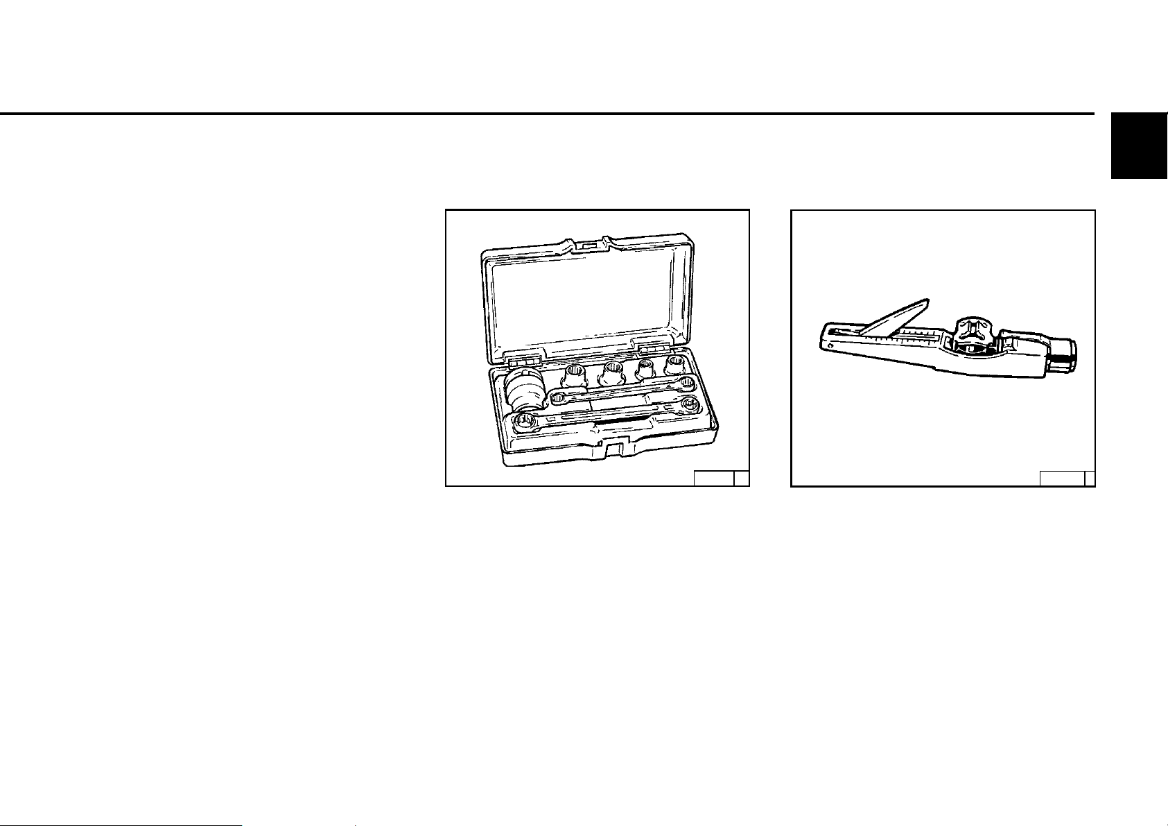
9.3 Tools Technical data
Ordering tools
The special tools listed in this chapter must be
ordered from:
FA.WILBÄR
Postfach 14 05 80
D-42826 Remscheid
http://www.deutz-tools.com
TORX V-belt tension measuring
device
25899 0
Order No. 8189
For engines of series 2012/2013, the TORX
screw system BN. 8189, amongst others, is
used.
This system was introduced due to its many
advantages:
Order No. 8115
Measuring device for checking the prescribed
V-belt tensions
9
©26 002 0
z Excellent screw accessibility.
z High transfer of force when loosening and
tightening.
z Slipping or broken wrenches and the risk
of injury associated with this is practically
impossible.
© 2005

Technical data 9.3 Tools
9
Rotation angle disc
© 43 202 1
Order No. 8190
Rotation angle disc for setting the valve/
control piston clearance.
Socket wrench insert
© 44 306 0 © 44 307 0
Order No. 8193 (5 mm) valve clearance
Order No. 8194 (4 mm) control piston
clearance. Wrench inserts for rotation angle
disc.
Crow's foot wrench
Order No. 8199
Crow's foot wrench for rotation angle disc
8190 in connection with commercially
available square bar extension.
© 2005

9.3 Tools Technical data
Turning gear
© 35 423 1
Order No. 100 330
For turning over the engine (as add-on on
the torsional vibration damper).
9
© 2005
 Loading...