


II DISASSEMBLY/REASSEMBLY
CAMSHAFT LOBE SPECIFICATIONS |
|
|||
NOTE: The camshaft shown in the fig |
||||
However, the cam lobes are identica |
||||
engines. The cam lobes are slightly |
||||
shown in the data below. |
|
|
||
H- F2/3/4M 1008 = Valve Lobe (intake |
||||
H- BF4M 1008, Intake Lobe |
= 29.438 |
|||
H- BF4M 1008, Exhaust Lobe |
= 29.778 |
|||
H- USEABLE Limit (All Models) |
= Min |
|||
H1 |
-Injection Lobe (All Models) |
= 28 |
||
H1 |
-Injection Lobe USEABLE Limit = 28 |
|||
LOBE IDENTIFICATION: |
|
|
||
A1No. 1 IntakeA2No. 2 IntakeA3No. 3 Intake |
||||
S1No. 1 ExhaustS2No. 2 ExhaustS3No. 3 Exhaust |
||||
I1No. 1 InjectionI2No. 2 InjectionI3No. 3 Injecti |
||||
CYLINDER HEAD REMOVAL |
|
|
||
Remove all cylinder head bolts, the |
||||
crankcase. Do not pry excessively, |
||||
with a hammer in attemptsdlooseto breakfrom |
||||
head gasket. Do not damage the pre- |
||||
the handling process. |
|
|
||
INSPECTION: Thoroughly clean the cy |
||||
solvent. Dry with compressed air. I |
||||
Check cylinder head warpage using |
||||
and precision feeler gauges. Hold t |
||||
head deck and check corner-to-corne |
||||
four(4) equidistant zonesrpage.Theis maxim0.10 |
||||
If warpage exceeds 0.10 mm, |
the cy |
|||
maximum of 0.20 mm. |
|
|
||
NOTE: Remove pre-combustion chamber |
||||
VALVE REMOVAL |
|
|
|
|
Components: |
4Spring |
|
|
|
1Valve Stem |
|
|
||
2Valve Seal |
5Spring Cap |
|
|
|
3Spring Seat |
6Collets |
|
|
|
Place the cylinder head on suitable |
||||
chambers do not touch the top of th |
||||
head is oriented as shown. Using a s |
||||
tool and acting5),on compressthespringthecapvalv( |
||||
that the6) colletscanbe removed( while the s |
||||
compressed state. WARNING: Valve spr |
||||
amount of energy while under compr |
||||
valve springs |
under compressionableeyewi |
|||
protectioncylinderexhaust° planessohead.thatAfter90.Removethethecylindercolletsthevalvesheadare. i
each valve according to cylinder nu reinstalled in the identical positi
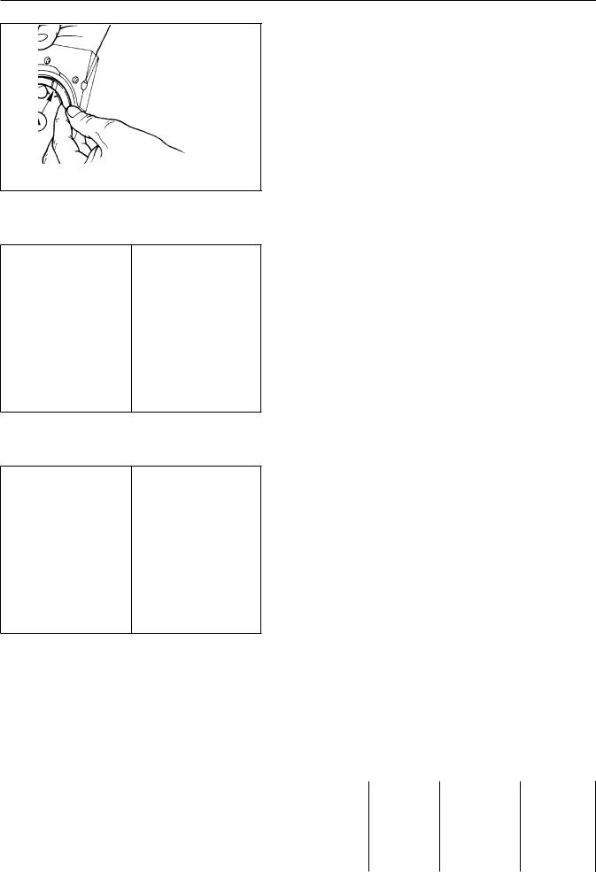
VALVE STEM SEAL INSTALLATION
Following cleaning of the cylinder the valves/ valve seats, install the wooden spacers to prevent pre-chamb head as shown. Soak new valve stem five(5) minutes. Liberally lubricat oil. Using special tool 1460-047, pl of the 1460-047 tool. Carefully pus stem and over the valve guide. Do no to drive the seals intoed placemust.beThepar to the valve.
© 2001 / 0297 9985 |
44 |

DISASSEMBLY/REASS
VALVE SPRINGS
INSPECTION:
Clean all valve springs in solve the springs for surface cracks normal direction of operation wi flat surface. Make sure that bo the springs seats are not parall Measure the free height of the free height should be 45.6 mm (n 43.5 mm, discard the spring.
VALVE SPECIFICATIONS:
INTAKE VALVE: Base Material: X Zone 1 - Chrome Plated C= 33.00 mm (F2/3/4M 1
α C=1=° 603430'.°4045'/mm60(F4M 1008
EXHAUST VALVE: Zone 2 - Weld Jo Zone 3 - Chrome Plated Zone 4 - Base Material Zone 5 - Base Material UNI 3992
D= 29.00 mm (F2/3/4M 1
α D=45°= 30'30° .2045'/45mm (F4M 1008
VALVE CLEANING: The face and lo power cleaned via an electric b VALVE STEM!
VALVE GUIDES / VALVE GUIDE BORE |
|||
Both intake and exhaust valve gu |
|||
are made from phosphoric gray |
|||
dimensional specifications are a |
|||
A |
= |
36.4 - 36.6 mm |
|
B |
= |
11.045 - 11.054mm |
|
C |
= |
11.000 - 11.018mm |
|
D |
= |
5.80 - |
6.20 mm |
E |
= |
9.75 - |
9.85 mm |
Valve guides are supplied in fi |
|||
standard valve guides is require |
|||
NOTE: 0.50mm oversizedOD) arevalavailabesgu |
|||
valve guides areC) used,from abovedimensionmus |
|||
by 0.50mm. |
|
||
VALVE GUIDE |
INSTALLATION GUI |
||
INSTALLATION VALVE/VALVE GUIDE |
|||
Deutz does not provide installa |
|||
recommends that valve guide rep |
|||
shop specializing in cylinder he |
|||
Whether newly installed or exist |
|||
to the following: |
|||
A |
= |
39.5 - 40.0 mm |
|
B |
= |
7.005 - |
7.020mm |
C |
= |
6.960 - |
6.990mm |
B-C= |
0.015 - |
0.050 mm; USAGE L |
|
45 |
© 2001 / 0 |

II DISASSEMBLY/REASSEMBLY
VALVE SEATS
Valve seats are supplied fully fini valve seats is required or recommen operation as part of valvenot installprovid installation tools for valve seats. replacement be done by a suitable s work. Whether newly installed or ex head interface must conform to the
For F2/3/4M 1008, BF4M 1008
EXHAUST VALVEA SEAT:=34.020 - 34.045 mm
α B1==° 593453'.° 10660- 34.115 mm INTAKE VALVE CSEAT:= 30.020 - 30.041 mm
α D ==° 443053'.° 10845- 30.116 mm
For F2/3/4M 1008 F
EXHAUST VALVEA SEAT:=35.220 - 35.245 mm
α B1==° 593553'.° 30660- 35.315 mm INTAKE VALVE CSEAT:= 31.220 - 31.241 mm
α D ==° 3153'44.° 30845- 31.316 mm
VALVE RECESS and SEAT SEALING WIDT
Invert the cylinder head as shown w suitable supports. Installvalvespringsthe valve.L the valve stems with clean engine o on the valve to valve seat interfac Wipe off all excess lapping compoun lapping and measure theS)widthas shownof thb the gray lap line.
For F2/3/4M 1008, BF4M 1008
SEALING SWIDTH)= 1.(6 - 1.7 mm; USEABLE L VALVE RECESSD) = 0.5( - 0.8 mm; USEABLE L With the valve resting in the cylin to determineD)thethatrecessthe valve( face cylinder head deck.
If valve recess or valve thesalingabovea specifications, replace the valves/
For F2/3/4M 1008 F
SEALING SWIDTH)= 1.(6 mm; USEABLE Limit =
VALVE RECESSD) = 0(.7 - 1.0 mm; USEABLE L
PRE-COMBUSTION CHAMBER-OVERVIEW
Components of the Pre-combustion ch 1Pre-combustion Chamber
2Glow Plug
3Pre-combustion Chamber Ring Nut
4Cylinder Head
NOTE: Pre-combustion chambersF2/3/4Mare100i and BF4M 1008.
© 2001 / 0297 9985 |
46 |

DISASSEMBLY/REASS
NOTE: THE PRE-COMBUSTION CHAMBER REQUIRE REMOVAL OR SERVICE AN DISTURBED UNLESS ABSOLUTELY NECE PRE-COMBUSTION CHAMBERS AS PART OR VALVE JOB. FURTHER, DEUTZ REC COMBUSTION CHAMBERS BE INSTALLE EXISTING PRE-CHAMBERS IS REQUI PROCEDURES DETAIL PRE-CHAMBER RE TION SHOULD SERVICE BE REQUIRED.
PRE-COMBUSTION CHAMBER RING NUT
As shown in the diagramheatprethe-comb chamber is secured to the cylind2) may be removed by securing the c mannerresting on wooden block chambers, then using special to loosen and remove2). the ring nut (
PRE-COMBUSTION CHAMBER REMOVAL
Remove the glow plug(s) from th 1460-030 into the pre-combustion comprised of1) shaft/endandslide2). (hammerMakesur( shaft/end1) portion( of the special t the pre-combustion chamber. Car hammer2) up( the special tool shaf end of the tool. The hammer effe pre-combustion chamber. preFollowin-comb chamber, unscrew the pre3) -frcombustthe tool.
WARNING: SPECIAL TOOL 7107-030 PROTECTION SHOULD BE WORN TION. GREAT CARE SHOULD BE THE PINCHING OF YOUR HAND SLIDE HAMMER IMPACTS THE T
PRE-COMBUSTION CHAMBER INSTALLA
Carefully clean all carbon from in the cylinder head. Do not us clean the pre-combustion chambe may be used to assist in carbon Introduce a new pre-combustion that the side hole of the prealigns with the glow plug hole chamber alignment tool 7107-031 hole, through the pre-chamber s chamber ring nut tool- 7107tall-027and the pre-combustion chamber ring steps100 Nm, then 180 Nm. Reinstall the glow plug. Torque
OIL PAN REMOVAL / INSTALLATION
REMOVAL: Drain the oil from the Gently, without deforming the p using a small bar(1). Numerous a around the perimeter of the pan releases from the crankcase.
INSPECTION/ CLEANING: Thoroughl and dry with compressedheairoil. Rempa from the oil pan and crankcase. cracks, dents, etc.. Inspect th clogging. Inspect the oil drain oil pan mounting flange on a f Repair or replace as required.
INSTALLATION: Install a new oil 7091 Silicone around the perimet as shown. Allow the silicone to Torque the oil pan bolts to 10 N
47 |
© 2001 / 0 |
II DISASSEMBLY/REASSEMBLY
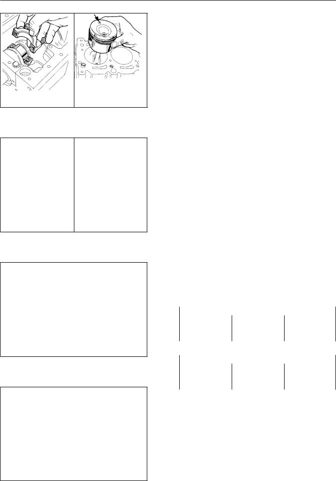
PISTON REMOVAL:Rotate the engine to BDC. |
|||||
the top of the cylinder bore. If a w |
|||||
cylinder bore, removedgethereamer”ridge .withRe |
|||||
the connecting rod cap as shown. Us |
|||||
and slowly push on the connecting r |
|||||
Do not allow the connecting rod to |
|||||
crankshaft rotation may be required |
|||||
connecting rod for purposes of push |
|||||
until the piston oil ring is outsid |
|||||
from the cylinder bore as shown. Ma |
|||||
connecting rod with respect to cyli |
|||||
the connecting rod cap to the conne |
|||||
GENERAL PISTONB/FMNOTES:1008/F pistons a |
|||||
the F2/3/4M 1008. BF4M 1008 piston |
|||||
1008, but is fitted with a special |
|||||
the BF4M 1008. |
|
|
|
||
PISTON / CONNECTING ROD DISASSEM |
|||||
INSPECTION |
|
|
|
||
Carefully remove and retain the pist |
|||||
using a suitable awl and a small s |
|||||
gram). Do not damage the snap ring s |
|||||
Push the piston wrististonpin farndencoughnne |
|||||
rod to be separated. NOTE: If requi |
|||||
with a soft faced drift to assist |
|||||
required, place the piston on a pro |
|||||
the piston is not damaged during th |
|||||
the drift to contact the piston pin |
|||||
INSPECTION: Clean the piston and pi |
|||||
compressed air. Inspect the piston |
|||||
localized overheating. Carefully re |
|||||
carbon from the piston top. Clean t |
|||||
using a suitable ring groove cleani |
|||||
MEASUREMENT: MeasureQ) theof thediameterpiston |
|||||
distanceA)-9 (mm from the bottom of the |
|||||
piston ring land/ ring clearance as |
|||||
PISTON CLASS, WEIGHT IMBALANCE an |
|||||
MARKINGS |
|
|
|
||
As part of the high quality standard |
|||||
B/FM 1008/F engines as a function o |
|||||
piston classesA, B,. TheexistC piston- |
class is |
||||
bottom of the piston as shown in th |
|||||
logo on the bottom of the piston cr |
|||||
piston is GENUINE DEUTZ. |
|
|
|||
PISTON CLASS DETAILS (F2/3/4M |
1008 |
||||
|
|
|
|||
CLASS Ø Cylinder (mm) |
Dimension |
||||
Ø Piston |
|||||
|
|
|
|
|
|
A |
71.990 - 72.000 |
71.930 - 71.94 |
|||
B |
72.000 - 72.010 |
||||
71.940 - 71.95 |
|||||
C |
72.010 - 72.020 |
||||
71.950 |
- 71.96 |
||||
PISTON CLASS DETAILS (F2/3/4M |
1008 |
||||
|
|
||||
CLASS Ø Cylinder (mm) |
Dimension |
||||
Ø Piston |
|||||
A |
74.990 - 75.000 |
74.930 - 74.94 |
|||
B |
75.000 - 75.010 |
||||
74.940 - 74.95 |
|||||
C |
75.010 - 75.020 |
||||
74.950 |
- 74.96 |
||||
REPLACEMENT PISTONS (SPAREReplacementPARTS):pi are supplied with pistonstonringsclassre. Replacement pistonsA.arePistonsuppliedB andclasseC as are reserved for production engines as 0.50mm and 1.00mm and are suppli of the oversized diameter. DO NOT F DARD PISTONS ON OVERSIZED PISTONS. FOR OVERSIZED PISTONS ON STANDARD P PISTON BALANCE: Weigh all pistons t engine. The total differencelightestinandweighe piston should not exceed 4 grams. W within a single engine. The total lightest and heaviest piston should
© 2001 / 0297 9985 |
48 |
DISASSEMBLY/REASS
CYLINDER INSPECTION / DIMENSION
Thoroughly clean the cylinders Alternately, completely clean th compressed air. Remove all carb carefully remove any excessive cylinder using a suitable “RIDGE for general wear, scoring, galli
shownfour(4)Using.aThepositions°calibratedintervalspistonringboreat45X),contact1each),2gauge,)while(and3)ofasz(t
skirt only contactZ). areaDimensionalis show follows:D = 71.990 - 72A.-000(Allmm,B/FMCLASS1 If the cylinder is foundatanyto bemas7 point, bore the cylinder by 0.50 found to be in specification,edor bellbuboring is suggested. NOTE:runningTo decl measure the piston skirt as det cylinder boreZ). Thein zonepiston( running difference between the two (2) d
CYLINDER CLASS
The cylinder class (at time of deck of the crankcase as shown i asA, B,dependingC on the exact cyl NOTE: Replacement pistonsA. Ifareupona sembly, the existing pistons can classA depending on the cylinder d
CYLINDER SURFACE FINISH
Proper cylinder surface finish optimal engine performance. The rebuild is greatly affected by respect to surface finish. After inspection of the cylinde should be power honed. A “BEAD” that do not require boring. Eng power honed as part of the bori material, the diameter-checkedof the cyas above following honing.
Theas shownhoninginoperationthe diagramshould.The°prof
0.5-1.0 mm.
POST HONING CLEANING: Deutz str cylinders be washed with hot wa following honing. Finish the cle with clean water, then dry the c exposed surfaces, especially the with clean engine oil to prevent NOTE: DO NOT USE EMERY CLOTH, S CYLINDER IN ATTEMPTS TO CREATE A BY HAND MOTION.
49 |
© 2001 / 0 |

II DISASSEMBLY/REASSEMBLY
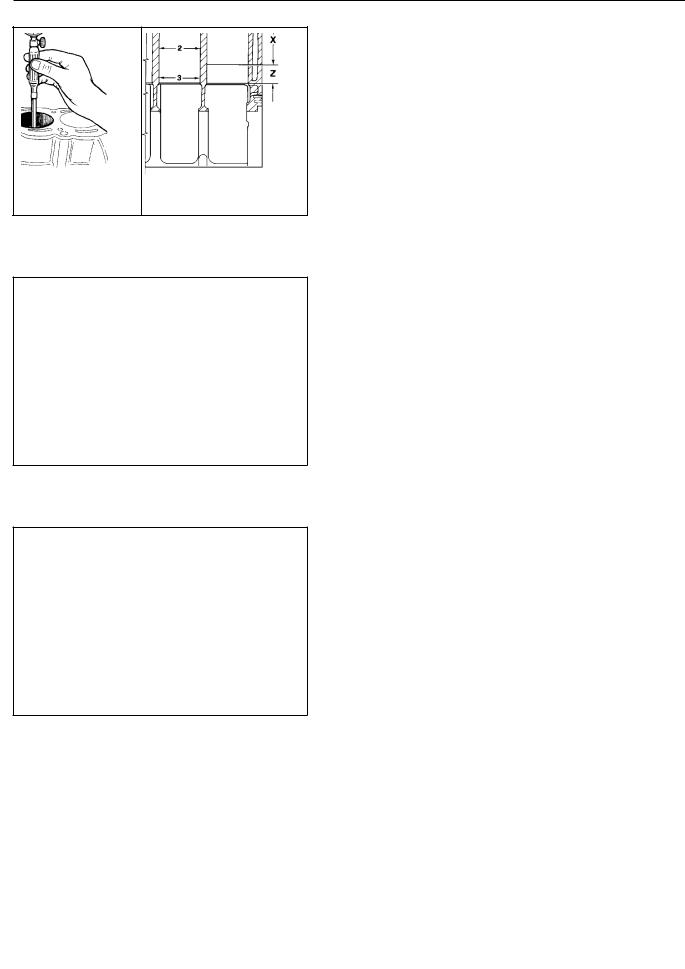
PISTON RING END GAP |
|
|
|||
Prior to installing piston rings on |
|||||
the cylinder bore, approximately 25 |
|||||
deck as shown. A piston turned upsid |
|||||
the rings to the 25mm depth so that |
|||||
can be had. Use a feeler gage(A) to |
|||||
specifications are as follows: |
|
||||
1st piston ring(compression)LE Limit= 0=.251.-0 |
|||||
2nd piston ring(compression)LE Limit= 0=.251.-0 |
|||||
3rd piston ring(oil scraper)LE Limit= =0.125.0- |
|||||
NOTE: If the ring gap is less than |
|||||
secure the ring in a soft jaw vise a |
|||||
ring, re-checking the end gap period |
|||||
is |
achieved. |
Remove all endsburrsbefromore |
|||
installation. |
|
|
|
||
PISTON RING TO PISTON LAND CLEARAN |
|||||
With reference to the diagrams, meas |
|||||
clearance using a feeler gage. If |
|||||
operated within and engine, the pi |
|||||
cleaned as described on page 36. |
|||||
The specifications forlearancepiston areringast |
|||||
A |
= |
0.090 - 0.125 mm |
|
|
|
B |
= |
0.050 - 0.085 mm |
|
|
|
C |
= |
0.040 - 0.075 mm |
|
|
|
Replace the piston and/or piston ri |
|||||
land clearance exceeds the specific |
|||||
PISTON RING ASSEMBLY LOCATION |
|
||||
With reference to the diagram, care |
|||||
the piston. |
|
|
|
||
A |
= Top Compression Ring (Tapered / |
||||
B = No. 2 Compression Ring (Tapered / |
|||||
C |
= Oil Control Ring (Internal Spri |
||||
D |
= Chrome Plated Portion of Top Co |
||||
E |
= Chrome Plated Portion of Oil Co |
||||
NOTE: As shown on the diagram, inst |
|||||
“top”, “UP” or any other markings f |
|||||
CONNECTING ROD / CONNECTING RO |
|||||
SPECIFICATIONS |
|
|
|||
INSPECTION / SET-UP: Remove the conn |
|||||
connecting rod bearingginsertsrod and. bearClea |
|||||
in solvent, then dry with compresse |
|||||
for nicks, gouges and potential str |
|||||
bushing for scratches andoverheatingindication.D |
|||||
the connecting rod if any doubt con |
|||||
the connecting rod exists. Inspect |
|||||
wear, dis-coloration, scatches and |
|||||
rod bearings if any doubt exists. I |
|||||
inserts (whether new or existing) i |
|||||
the connecting rod cap.rodSeecapageorient41 |
|||||
and torque specificationsimensional.The fol |
|||||
specifications for a fully)andassembltorqu |
|||||
connecting rod. Replace the connect |
|||||
bearings if dimension conformance t |
|||||
Dim. |
|
SPECIFICATION |
NOTES |
||
A = 126.48 - 126.520 mm |
BF4M 1008 = |
||||
B = |
|
18.015 - 18.025 mm |
|||
C = |
|
40.021 - 40.050 mm |
(Cap Torqued |
||
D = |
|
17.996 - 18.000 mm |
BF4M 1008 = |
||
E= |
|
50.900 - 51.100 mm |
BF4M 1008 = |
||
B-D= |
0.015 - |
0.039 mm USEABLITY |
|||
NOTE: If the small end bushing is r be aligned
© 2001 / 0297 9985 |
50 |

DISASSEMBLY/REASS
CONNECTING ROD ALIGNMENT
Check the alignment of the conne to the connecting rod journal di a suitable fixture as shown or mandrel in V-blocks as shown. method is used, center the wris bore so that an equal amount of side of the connecting rod. Whi seated in the wrist pin bushing, both sides of the connectingthodis rodus down on the wrist pin as shown a Maximum Axial Mis-alignmentimit==.015. Minor mis-alignment may be corr working the connecting rod betw ATTEMPT TO CORRECT MIS-ALIGNMEN TRAINED AND EXPERIENCED.
PISTON WRIST PIN INSTALLATION /
After thoroughly cleaningng androd described in the previous, liber bore and wrist pin bushing with piston and connecting rod as sh piston and through the connectin use a hammer or drift Ifpinhandto insfo install the wrist pin, investiga Install the piston pin retaining ring are oriented as shownaldistancein th the piston centerline and the o equal on both sides. The snap ri after installation by carefully awl atA)point. (
CONNECTING RODPISTON ASSEMBLY
Weigh the connecting rod / pist given engine. The maximum allowa lightest and heaviest assembly i If the 10 gram differential in pistons and/ or connecting rods grams or less.
PISTON / CONNECTING ROD INSTALL
With reference to the cylinder b page 38 and the information pres rings and connecting nectingrods,instarod Rotate the engine so thatorpiston/the re rod installation is at BDC. Clea rod journal with clean engine o Install the upper and lower con Liberally coat the connecting ro
theringringswristendwithgappincleanisaxis)locatedengineand °thaton±oil° 10the.froallRot
120Compress° relativethetopistoneach otherrings. with
piston so that the turbulence ch correspond to the pre-combustio Gently lower the piston / conne taking extreme care not to cock the connecting rod from contact center of the piston with the w guiding the connecting rod over
51 |
© 2001 / 0 |
|
II |
DISASSEMBLY/REASSEMBLY |
|
|
|
|
||||||||
|
|
|
|
|
|
CONNECTING BEARING / ROD CAP INSTA |
||||||||
|
|
|
|
|
||||||||||
|
|
|
|
|
|
Install the connecting rod bearing |
||||||||
|
|
|
|
|
|
connecting rod cap. Make sure that t |
||||||||
|
|
|
|
|
|
the connecting rod and connecting ro |
||||||||
|
|
|
|
|
|
etc. Insert the bearing inserts so |
||||||||
|
|
|
|
|
|
with the slot in the connecting rod |
||||||||
|
|
|
|
|
|
bearing completely into the connect |
||||||||
|
|
|
|
|
|
Liberally oil the bearings with cle |
||||||||
|
|
|
|
|
|
rod cap onto the connecting rod maki |
||||||||
|
|
|
|
|
|
slot locks on the connecting rod cap |
||||||||
|
|
|
|
|
|
the connecting rod. |
|
|
|
|
||||
|
|
|
|
|
|
Torque the connecting rod bolts to |
||||||||
|
|
|
|
|
|
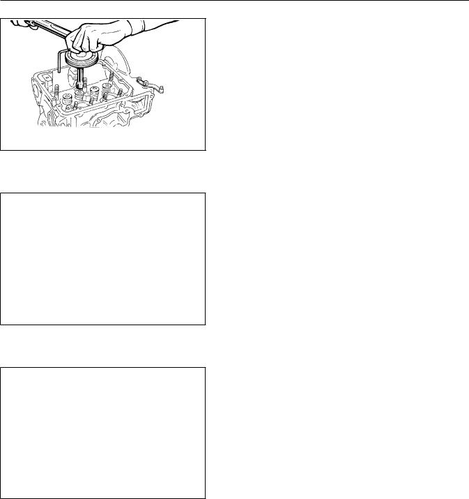
PISTON PROTRUSION |
|
|
|
|
||||
|
|
|
|
|
|
|
|
|
||||||
|
|
|
|
|
|
Rotate each cylinder to exact TDC. |
||||||||
|
|
|
|
|
|
use of a dial indicator mounted to |
||||||||
|
|
|
|
|
||||||||||
|
|
|
|
|
|
piston height as a function of cran |
||||||||
|
|
|
|
|
|
After TDC is established,themeasurepisto |
||||||||
|
|
|
|
|
|
(A) from the cylinder deck plane usin |
||||||||
|
|
|
|
|
|
The height should be measured on a |
||||||||
|
|
|
|
|
|
pin axis as |
shown. |
Recorde theTDC pr |
||||||
|
|
|
|
|
|
establishment |
and piston protrusion |
|||||||
|
|
|
|
|
|
recording the value for protrusioneachcylin |
||||||||
|
|
|
|
|
|
measured will be used to establish |
||||||||
|
|
|
|
|
|
as presented below. |
|
|
|
|
||||
|
|
|
|
|
|
HEAD GASKET SELECTION/ INSTALLATIO |
||||||||
|
|
|
|
|
|
Three(3) separate head gasket thic |
||||||||
|
|
|
|
|
|
1008/F engines depending on the me |
||||||||
|
|
|
|
|
||||||||||
|
|
|
|
|
|
measured above. The head gaskets ar |
||||||||
|
|
|
|
|
|
the edge locatedB) as atdetailedpoint (below. H |
||||||||
|
|
|
|
|
|
provided with “0 notch”, “1 notch” |
||||||||
|
|
|
|
|
|
For F2/3/4M 1008, BF4M 1008 |
|
|||||||
|
|
|
|
|
||||||||||
|
|
|
|
|
|
A (mm) |
PROTRUSION) |
|
No. of |
hole |
||||
|
|
|
|
|
|
(PISTON |
|
|||||||
|
|
|
|
|
|
Head Clearance (mm) |
|
|
|
|
|
|||
|
|
|
|
|
|
0.97 - 1.006 |
|
|
0.39 - |
0.48 |
||||
|
|
|
|
|
|
1.07 - 1.116 |
|
|
||||||
|
|
|
|
|
|
1.17 - 1.225 |
|
|
0.40 - |
0.48 |
||||
|
|
|
|
|
|
For F2/3M 1008 F |
|
|
|
|||||
|
|
|
|
|
|
|
|
|
|
|
|
|||
|
|
|
|
|
|
A (mm) |
|
|
|
|
|
|
|
|
|
|
|
|
|
|
(PISTON |
PROTRUSION) |
|
No. |
of |
hole |
|||
|
|
|
|
|
||||||||||
|
|
|
|
|
|
Head Clearance (mm) |
|
|
|
|
|
|||
|
|
|
|
|
0.82 - 0.091 |
|
|
0.55 - |
0.63 |
|||||
|
|
|
|
|
|
0.92 - 1.101 |
|
|
||||||
|
Match the piston protrusion dimension determined |
|
||||||||||||
|
above |
with A)dimensionfrom the( |
chart1..02Install- 1.210the |
0.55 - |
0.63 |
|||||||||
|
|
|
||||||||||||
|
corresponding head gasket. If a head gasket cannot be |
|||||||||||||
|
chosen based upon the |
pistonFor F4Mprotrusion1008 F |
measured, |
|
||||||||||
|
|
rod bearings, wrist |
|
|||||||||||
|
check |
the |
connecting |
rod length, |
|
|||||||||
|
|
|
|
|
|
A (mm) |
the problem. |
|
||||||
|
pin bushing, etc. for the cause of |
|
||||||||||||
|
|
|
|
|
|
(PISTON |
PROTRUSION) |
|
No. |
|
of |
Notches |
||
|
|
|
|
|
|
Head Clearance (mm) |
|
|
|
|
||||
|
Completely |
clean the |
deck surface of oil, old |
gasket |
|
|||||||||
|
|
|
|
|
0.82 - 0.191 |
|
|
|
|
|
|
|||
|
material, varnish, coolant, etc. Remove all traces |
of |
||||||||||||
|
fluid from the cylinder head bolt bores. Install0.52the- |
head0.61 |
||||||||||||
|
|
|
|
|
0.92 - 1.201 |
|
|
|
|
|
|
|||
|
gasket so that the gasket aligns with the deck dowels |
|
||||||||||||
|
and the brand name or “TOP” printed on the gasket |
|
||||||||||||
|
faces up. |
|
|
1.02 - 1.310 |
|
|
0.53 - |
0.61 |
||||||
|
|
|
|
assist in the identification of the |
||||||||||
|
108 |
|
109 |
|
|
|||||||||
|
|
52 |
|
|
|
|
|
|
|
|
||||
|
© 2001 / 0297 9985 |
|
|
|
|
|
|
|
|
|||||
DISASSEMBLY/REASS
CYLINDER HEAD INSTALLATION
Cylinder head bolts are tighten method as opposed to the traditi the bolts are pre-loaded, then bolts are tensioned exactly the initial pre-load stretches the b PREPARATION: Clean the cylinder gasket material, rust, etc. Clea all gasket material, boltdeposits,thread the length of the head bolts. 90.5mm. Each time the bolts are DO NOT USE HEAD BOLTS WITH MEASU OR GREATER. In general terms, he times before replacement. Libera bolt head thrust area and washer the instructions on page 41. Ge crankcase aligning the index do wrench with a dividing head as s
CYLINDER HEAD TIGHTENING PROCE F2/3M 1008 F:
FIGUREA = F2M 1008, F2M 1008 F FIGUREB = F3M 1008, F3M 1008 F STEP 1: Torque the head bolts to
STEPSTEPshown3:2:. RotateRotate eacheach headhead° |
(cbobolockwt,t,ii |
° |
(clockw |
NOTE: NO POST OPERATION RE-TORQUEAD IS REQUIRED OR RECOMMENDED.
CYLINDER HEAD TIGHTENING PROCE 1008 F, BF4M 1008
STEP 1: Torque the head bolts to
STEPSTEPshown3:2:. RotateRotate eacheach headhead° |
(cbobolockwt,t,ii |
° |
(clockw |
NOTE: NO POST OPERATION RE-TORQUE OF THE CYLINDER HEAD IS REQUIRED OR RECOMMENDED.
|
|
|
53 |
© 2001 / 0 |
|
II DISASSEMBLY/REASSEMBLY
|
|
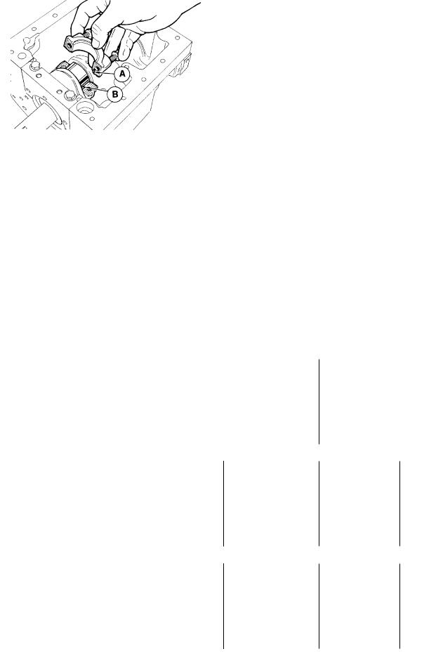
MAIN BEARING CAPS / BEARINGSCENT |
|||||
|
|
||||||
|
|
The center main caps are referenced |
|||||
|
|
crankcase as shown to allow replace |
|||||
|
|
position of removal. The reference n |
|||||
|
|
figure at the left. Always repositi |
|||||
|
|
NOTE: If main bearings areollowingintend |
|||||
|
|
disassembly, mark the bearing posit |
|||||
|
|
INSPECTION / CLEANING: Clean the ma |
|||||
|
|
and dry with compressed air. Remove |
|||||
|
|
the bearing seats. Check/ clean all |
|||||
|
|
all |
impurities. Flush theolventoil befopass |
||||
|
|
assembling the crankshaftg.capsInspecand |
|||||
|
|
crankcase for cracks, signs of over |
|||||
|
|
main bearings for wear and signs of |
|||||
|
|
etc. Thoroughly scrub, but do not d |
|||||
|
|
||||||
|
|
(back side) of the main bearings if |
|||||
|
|
main bearings if any doubt exists. |
|
||||
|
|
BEARING INSTALLATION / TORQUEltheSPECIFmain |
|||||
|
|
bearings (upper and lower) into the |
|||||
|
|
aligning the “tang” on the bearing |
|
||||
|
|
Liberally oil the bearing surface w |
|||||
|
|
bearing caps with reference to orig |
|||||
|
|
the main bearing caps to 60 Nm in 1 |
|||||
|
|
FRONT / REAR MAIN BEARING CAPS / B |
|||||
|
|
The front and rear main bearings o |
|||||
|
|
designed with2) lateralinstalledsealsbetween( |
the |
||||
|
|
bearing cap and the crankcase saddl |
|||||
|
|
replaced each time the main bearing |
|||||
|
|
clean the main bearing cap and crank |
|||||
|
|
and lubricate the main bearings as |
|
||||
|
|
bearings (rear main only) as descri |
|||||
|
|
seals onto |
the 1)main.Liberallyaring lubricacap( |
||||
|
|
the seals. Place the special shims ( |
|||||
|
|
figure between the crankcase and th |
|||||
|
|
||||||
|
|
bearing into place. Remove the shim |
|||||
|
|
front and rear main bearing caps to |
|||||
|
|
installation, the lateral seal mus |
|||||
|
|
crankcaseA)planesatthe(front and rear fa |
|||||
|
|
0.5-1.0 mm pastB)thetooilalowpancomplplanete( |
|||||
|
|
||||||
|
|
material in excess of 1.00 mm with |
|||||
|
|
installation of the rear seal suppo |
|||||
|
|
small amount of RTV Silicone to the |
|||||
|
|
MAIN BEARING CLEARANCE |
|
|
|||
|
|
Ideally, main bearing clearanwingcetualis |
|||||
|
|
measurement of the main bearing jo |
|||||
|
|
diameters. “PLASTIGAGE” however,kand |
c |
||||
|
|
reasonably |
accurate determination |
o |
|||
|
|
view and understand thetheinstructions“PLASTIGAG |
|||||
|
|
kit. Invert (if possible) the engi |
|||||
|
|
directed away from the main bearing |
|||||
|
|
cap in question. Clean all oil from |
|||||
|
|
using a spray solvent. Place a smal |
|||||
|
|
main bearingA)as. Installshownatand( torque t |
|||||
|
|
60 Nm. DO NOT ROTATE THE ENGINE!. R |
|||||
|
|
||||||
|
|
cap and compare the width of the co |
|||||
|
|
the “KEY” provided with the PLASTIG |
|||||
|
|
the bearing clearance. |
|
|
|||
|
|
PISTON COOLING JETSTheBF4M 1008: en |
|||||
|
|
equipped with cooling jets which sp |
|||||
|
|
the piston providing additional engi |
|||||
|
|
to the crankcase directly adjacent |
|
||||
|
|
COMPONENTS: |
SPECIFICATIONS: |
|
|
||
|
|
1 Washer |
A = 0.80 - 0.85mm |
|
|
||
|
|
2 Nozzle |
B = 34 mm |
|
|
||
|
|
3 Washer |
C = 150 mm |
|
|
||
|
|
654 CheckSpringBanjoBallBoltα D=°=516 mm |
|
|
|||
|
|
INSPECTION / CLEANING / INSTALLATION |
|||||
|
|
damage and clogging1.),3Using),( affixnew2)thewashn |
|||||
|
|
to the crankcase4). Slowlywith brotatelt( the en |
|||||
|
|
cylinder). Adjust the2) sopositionthat noofcot |
|||||
|
|
made with the piston at BDC and the |
|||||
|
|
||||||
|
|
the piston bottom4). Torque the bolt |
|
||||
© 2001 / 0297 9985 |
|
54 |
|
|
|
|
|
DISASSEMBLY/REASS
THRUST BEARINGS |
|
|
|
Thrust bearings on the B/FM 1008 |
|||
main bearing cap and the crankc |
|||
consists of four(4) separate th |
|||
segments are supported by the c |
|||
are supported by the rear main |
|||
bearing segments act upon the cr |
|||
INSPECTION: Thoroughly clean th |
|||
bearing socket and the crankcase |
|||
the thrust bearings for indicat |
|||
and |
general condition. Inspect |
||
galling, scratches, pitting, etc |
|||
INSTALLATION: Liberally coat the |
|||
clean engine oil and install by |
|||
crankcase thrust |
bearing socket |
||
The |
bearings must |
be installedsurface, as |
|
by |
oil Agrooves)is oriented( |
toward the |
|
The main bearing cap thrust bear bearing reliefs and indexed wit diagram. The thrust bearings mus (A) face the crankshaftatthrustthe hrusu with clean engine oil, then ins instructions presented on page 4 (crankcase side) do not include locational index.
CRANKSHAFT END PLAY
After installing allearings,mabearinthe end play may be measured.
1. Push the crankshaft toward th
2. Using a feeler gage, measure bearing wear surface and the cra SPECIFICATIONS:
A = 0.130 - 0.313mm (Wear Limit B = 23.05 - 23.10mm (Wear Limit If the crankshaft end play exce engine with oversize thrustgrindbe crankshaft thrust surfaces. The application of oversize bearings surfaces.
|
|
THRUST SURFACE SPECIFICATIONS- |
||||||||
|
|
CORRECTIONS |
|
|
|
|
||||
|
|
Depending on the condition/ wid |
||||||||
|
|
facesB) (above figure)C ofandofthewidma |
||||||||
|
|
thrust bearing socket/ thrust b |
||||||||
|
|
end play can be corrected in se |
||||||||
|
|
and 0.2mm oversized thrust1),bearisid2) |
||||||||
|
|
or both. The following table pr |
||||||||
|
|
thrust bearing width, ringthrustcapsur/ |
||||||||
|
|
and crankshaft thrust surface wi |
||||||||
|
|
TABLE KEY: |
|
|
|
|
|
|||
|
|
A |
= |
Crankshaft End Play (resul |
||||||
|
|
B |
= |
Width of crankshaft thrust |
||||||
|
|
|
|
|
|
|
|
|||
|
|
THRUST |
BEARING |
B (mm) |
A (m |
|||||
|
|
COMBINATION |
(mm) |
|||||||
|
|
|
|
|
|
|
|
|
||
|
|
Standard |
22.787-22.920 |
23.050- |
||||||
|
|
|
|
|
|
|
||||
|
|
0.1 mm (both sides) 22.987-23.120 2 |
||||||||
|
|
0.1 mm (one sides) |
0.130- .31 |
|||||||
|
|
23.087-23.220 2 |
||||||||
|
|
0.2 mm (one sides) |
|
|
|
|
||||
|
|
0.2 mm (both sides) 23.187-23.320 2 |
||||||||
|
|
|||||||||
55 |
|
|
|
|
© 2001 / 0 |
|||||
II DISASSEMBLY/REASSEMBLY
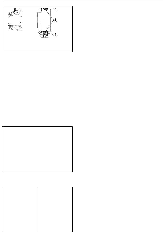
CRANKSHAFT SEALS - FRONT and REAR
The front seal for the B/FM 1008/F oil pump assembly. The rear oil sea support. Deutz recommends that oil from the supporting bores. The oil upon inspection, signs of hardening exterior or dry rot is noted.
SEAL DETAILS:
A Seal Support
B Seal
1 Installation depth plane (initial)
2 Installation depth plane (initial)
3 Crankshaft wear surfacefront
4 Crankshaft wear surfacerear INSTALLATION: Remove the oil pump upon front or rear seal replacement seal supporting bore, aprefullythe sealclean non abrasive manner, the wear surfac seal in clean engine oil.Coatfortheapproxicran with clean engine oil. Using a suit push the seal into the bore until t planes1) or2)(. (Reinstall the oil pump or gaskets as required. Torque the rear Nm. Torque the oil pump retaining b NOTE: If the wear surface of the cra at the initial installation depth r the bore an additional 2 mm using a
CRANKSHAFT LUBRICATION DRILLINGS-
The lubrication drillings for the F in the diagram. The lubrication dr BF4M 1008 are very similar to the F CLEANING: Remove2) byplugssuitableat ( means crankshaft in solvent to loosen any the drillings1) and2) by( (blowing with compres brushes, etc.. 2Cap)withthe newdrillingsplugs. at
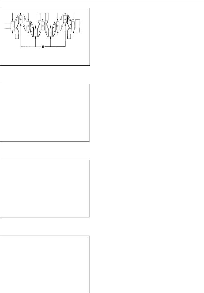
CRANKSHAFT JOURNAL INSPECTION / ME
INSPECTION: Inspect each journal ( scoring, grooves and generalkshaft wearormac.R as required. See page 456for dimens
MEASUREMENT:withintervalsa calibratedaroundWith thereferencemicrometercircumferenceeachto.° Eachjournthedj
position shown on the left most dia two seperate parts of the given dia journal and once near the fillet of
© 2001 / 0297 9985 |
56 |
DISASSEMBLY/REASS
CRANKSHAFT JOURNAL SPECIFICATIO
For F2/3/4M 1008, BF4M 1008
A = Main Journals = 47.984 - 48.
For F2/3/4M 1008 F
A = Main Journals = 50,981 - 51.
For B/FM 1008/F
B = Rod Journals = 39.984 - 40.0
UNDERSIZED BEARINGSROD and MA |
|
Undersized connecting rod and m |
|
0.25 and 0.50mm. Use of thelrequun |
|
the nominal size of the rod/ ma |
|
0.50 mm respectively. |
|
MAIN and CONNECTING ROD BEARING |
|
The dimensions shown reflect cl |
|
inserts. |
|
For F2/3/4M 1008, BF4M 1008 |
|
C = Main Bearings = 47.9848.-05548. |
|
C-A= 0.022 - 0.074 mm (WEAR Limit |
|
For F2/3/4M 1008 F |
|
C = Main Bearings = 51,02351,098- |
|
C-A= 0.023 - 0.078 mm (WEAR Limi |
|
For B/FM 1008/F |
|
D = Rod Bearings = 40.02140.-1040. |
|
D-B= 0.021 - 0.066 mm (WEAR Limi |
|
HYDRAULIC PUMP PTO- (No. 3 PTO) |
|
All B/FM 1008/F diesel engines |
|
driveA) as( shown. The hydraulic dr |
|
the engine camshaft. |
|
Hydraulic |
pump adaptations for |
BOSCH pumps are available. |
|
DRIVE SPECIFICATIONS: |
|
Speed Ratio: 1 : 2, or 1/2 engin |
|
Maximum Torque = 37 Nm, irrespec |
|
NOTE: |
37 Nm @ 3600 r/min c |
HYDRAULIC DRIVE COMPONENTSNo. |
||
1 |
Splined Drive- (Bolts to Camsh |
|
2 |
Pump Drive Gear (Attaches to P |
|
3 |
O-Ring |
|
4 |
Pump Support (Bolts to Cylinde |
|
5 |
O-Ring |
the ecc |
The splined1) alsodriveincludes( |
||
The splined drive must be bolted 80 Nm. The pump2) mustdrivebegeartorqued( pump input shaft. Check with th specifications at the input shaf
57 |
© 2001 / 0 |
 Loading...