

26 472
Operation Manual
912
913
1 Gerade

Safety guidelines / Accident prevention
● Please read and observe the information
given in this Operation Manual. This will
enable you to avoid accidents, preserve the
manufacturer’s warranty and maintain the
engine in peak operating condition.
● This engine has been built exclusively for
the application specified in the scope of
supply, as described by the equipment manufacturer and is to be used only for the
intended purpose. Any use exceeding that
scope is considered to be contrary to the
intended purpose. The manufacturer will
not assume responsibility for any damage
resulting therefrom. The risks involved are
to be borne solely by the user.
● Use in accordance with the intended purpose also implies compliance with the conditions laid down by the manufacturer for
operation, maintenance and servicing. The
engine should only be operated by personnel trained in its use and the hazards involved.
● The relevant accident prevention guidelines
and other generally accepted safety and
industrial hygiene regulations must be observed.
● When the engine is running, there is a risk of
injury through:
- turning/hot components
- engines with positive ignition
- ignition systems (high electrical voltage)
You must avoid contact at all times!
● Unauthorized engine modifications will invalidate any liability claims against the manufacturer for resultant damage.
Manipulations of the injection and regulating
system may also influence the performance
of the engine, and its emissions. Adherence
to legislation on pollution cannot be guaranteed under such conditions.
● Do not change, convert or adjust the cooling
air intake area to the blower.
The manufacturer shall not be held responsible for any damage which results from
such work.
● When carrying out maintenance/repair operations on the engine, the use of DEUTZ
original parts is prescribed. These are specially designed for your engine and guarantee perfect operation.
Non-compliance results in the expiry of the
warranty!
● Maintenance and cleaning of the engine
should only be carried out when the engine
is switched off and has cooled down.
You must ensure that the electrical systems
have been switched off and the ignition key
has been removed.
Accident prevention guidelines concerning
electrical systems (e.g. VDE-0100/-0101/0104/-0105 Electrical protective measures
against dangerous touch voltage) are to be
observed.
When cleaning with fluids, all electrical components are to be covered impermeably.
00_GB.p65 04.02.2002, 14:232

Engine
Serial Number
Please enter the engine serial number here. This
number should be quoted when inquiring about
Customer Service, Repairs or Spare Parts (see Section
2.1).
Operation Manual
912
913
0297 9690 en
All rights reserved. Technical modifications required
to improve our engines are reserved with regard to
specification data and other technical information
contained in this Operation Manual. No parts of this
Manual may be reproduced in any form or by any
means without our written approval.
3 Gerade

Foreword
Dear Customer,
1
Air / liquid-cooled DEUTZ engines are designed for a
large number of applications. Consequently, a wide
range of variants are offered to meet the requirements
of specific cases.
Your engine is appropriately equipped for the
installation concerned, which means that not all of
the components described in this Operation Manual
are necessarily mounted to your engine.
We have endeavoured to highlight any differences so
that you will be able to locate the operating and
maintenance instructions relevant to your engine
quickly and easily.
Please read this Manual before starting your engine,
and always observe the operating and maintenance
instructions.
We are available to help with any additional inquiries
Sincerely,
DEUTZ AG
4 4

Index
1 General
2 Engine Description
2.1 Model
2.1.1 Rating Plate
2.1.2 Rating Plate Location
2.1.3 Engine Serial Number
2.1.4 Cylinder Numbering
2.1.5 Direct Injection
2.1.6 Two-stage Combustion
2.2 Engine Illustrations
2.2.1 Service Side F4L 912
2.2.2 Exhaust Side F4L 912
2.2.3 Service Side BF4L 913
2.2.4 Exhaust Side BF4L 913
2.3 Lube Oil Circuit
2.3.1 Lube Oil Circuit FL 912/913
2.4 Fuel System Schematic
2.4.1 Fuel Circuit
2.5 Engine Cooling
2.5.1 Regulation of Coolant Flow using the
Exhaust Thermostat
2.5.2 Regulation of Coolant Flow using the
Exhaust Thermostat and Solenoid
3 Engine Operation
3.1 Commissioning
3.1.1 Adding Engine Oil
3.1.2 Filling Oil Bath Air Cleaner
3.1.3 Adding Fuel
3.1.4 Ventilation
3.1.5 Other Preparations
3.1.6 Additional Maintenance Work
3.1.7 Selector Switch for Oil Heater
3.2 Starting
3.2.1 Electric Starting
3.3 Monitoring Systems
3.3.1 Engine Oil Pressure
3.3.2 Engine Temperature
3.3.3 Cooling Fan Drive
3.4 Stopping
3.4.1 Mechanical Shutdown
3.4.2 Electrical Shutdown
3.5 Operating Conditions
3.5.1 Winter Operation
3.5.2 High Ambient Temperatures, High Altitude
4 Operating Media
4.1 Lube Oil
4.1.1 Quality Grade
4.1.2 Viscosity
4.2 Fuel
4.2.1 Quality Grade
4.2.2 Winter-Grade Fuel
5 Routine Maintenance
5.1 Maintenance Schedule
5.2 Maintenance Chart
5.3 Maintenance Work Completed
6 Service and Maintenance
6.1 Lube Oil System
6.1.1 Oil Change Intervals
6.1.2 Checking Oil Level / Changing Oil Level
6.1.3 Changing Oil Filter
6.1.4 Changing the Partial-Flow Oil Filter Insert
6.2 Fuel System
6.2.1 Changing Fuel Filter
6.2.2 Fuel Precleaner Cleaning the Fuel Filter
6.3 Cooling System
6.3.1 Cleaning Intervals
6.4 Combustion Air Filter
6.4.1 Cleaning Intervals
6.4.2 Emptying Cyclone Type Precleaner
6.4.3 Cleaning Oil Bath Air Cleaner
6.4.4 Dry Type Air Cleaner
6.5 Belt Drives
6.5.1 Checking V-Belts
6.5.2 Changing the Fan V-Belt
6.5.3 Tensioning Alternator Belts
6.5.4 Changing Alternator Belts
6.5.5 Checking Warning System
6.5.6 Tensioning and Changing Air Compressor
V-Belts
6.5.7 Air Compressor Design with Double
V-Belt
6.6 Adjustments
6.6.1 Checking / Adjusting Valve Clearance
6.7 Accessories
6.7.1 Battery
6.7.2 Three-Phase Alternator
6.7.3 Lifting Tackle
6.8 Cleaning the Engine
6.8.1 Cleaning the Engine
6.9 Additional Maintenance
6.9.1 Checking the Mountings
6.9.2 Checking the Function of the
Heating Pipe
6.9.3 Checking the Function of the Flame
Glowing System
7 Faults, Causes and Remedies
7.1 Diagnosis Chart
8 Engine Preservation
8.1 Preservation
8.1.1 Preserving Engine
8.1.2 Removing Engine Preservatives
9 Technical Specifications
9.1 Engine Specifications and Settings
9.2 Torque Wrench Settings
9.3 Tools
10 Service
AZ-TD3/Vo 19.7.96 5
1
26 472
6 6
General
DEUTZ Diesel Engines
are the product of many years of research and
development. The resulting know-how, coupled
with stringent quality standards, guarantee their
long service life, high reliability and low fuel
consumption.
It goes without saying that DEUTZ Diesel Engines
meet the highest standards for environmental
protection.
Beware of Running Engine
Shut the engine down before carrying out maintenance or repair work. Ensure that the engine cannot
be accidentally started. Risk of accidents.
When the work is complete, be sure to refit any
panels and guards that may have been removed.
Never fill the fuel tank while the engine is running.
Observe industrial safety regulations when running
the engine in an enclosed space or underground.
Care and Maintenance
Sound care and maintenance practices will ensure
that the engine continues to meet the requirements
placed on it. Recommended service intervals must
be observed and service and maintenance work
carried out conscientiously.
Special care should be taken under abnormally
demanding operating conditions.
Safety
This symbol is used for all safety
warnings. Please follow them
carefully. The attention of operating
!
personnel should be drawn to these
and accident prevention regulations laid down by
law must also be observed.
safety instructions. General safety
Asbestos
Service
1
Please contact one of our authorized service
representatives in the event of breakdowns or for
spare parts inquiries. Our trained specialists will
carry out repairs quickly and professionally, using
only genuine spare parts.
Original parts from DEUTZ AG are always produced
in accordance with state-of-the-art technology.
Please turn to the end of this manual for further
service information.
California
Proposition 65 Warning
Diesel engine exhaust and some of its constituents are known to the State of California to
cause cancer, birth defects, and other reproductive harm.
9690en_K01_neu 18.08.2000, 14:56 Uhr7
DEUTZ original parts are asbestosfree.
7 Gerade
7 Gerade

1
8 8
9690en_K01_neu 18.08.2000, 14:56 Uhr8

2.1 Model
2.2 Engine Illustration
2.3 Lube Oil Circuit
2.4 Fuel System Schematic
2.5 Engine Cooling
Engine Description
2
9
9 Gerade
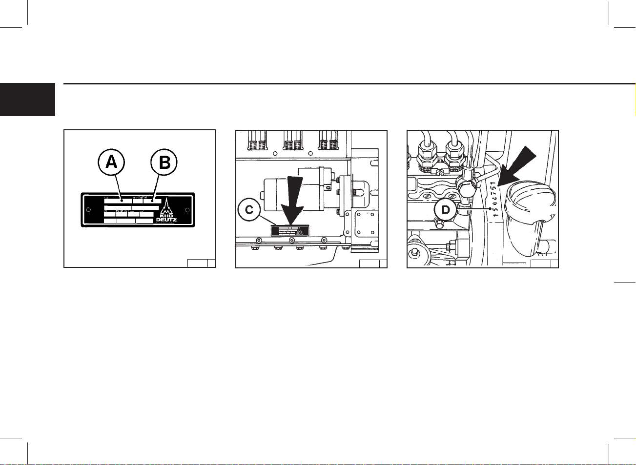
Engine Description 2.1 Model
2.1.1 Rating Plate
2
The model A, the engine serial number B and the
performance data are stamped on the rating plate.
The model and engine serial number must be given
when ordering parts.
25 611 2
2.1.2 Rating Plate Location 2.1.3 Engine Serial Number
24 587 1 24 552 1
The rating plate C is attached to the crankcase;
depending on the design, a second rating plate may
be attached to the air duct.
The engine serial number D is stamped on the
crankcase as well as the rating plate.
10
10
2.1 Model Engine Description
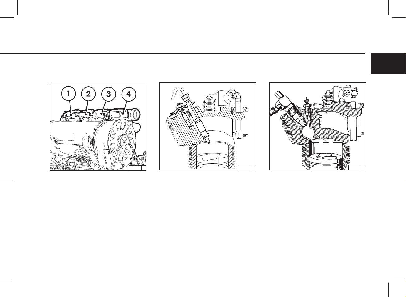
2.1.4 Cylinder Numbering
24 858 1
Cylinders are numbered consecutively, beginning
at the flywheel end.
2.1.5 Direct Injection
FL 912
21 878 3 26 045 0
Engines with direct injection are used where high
performance is required.
2.1.6 Two-stage Combustion
FL 912W
Engines with two-stage combustion are used where
it is particularly important to keep exhaust emissions
to an absolute minimum.
2
11
11 Gerade
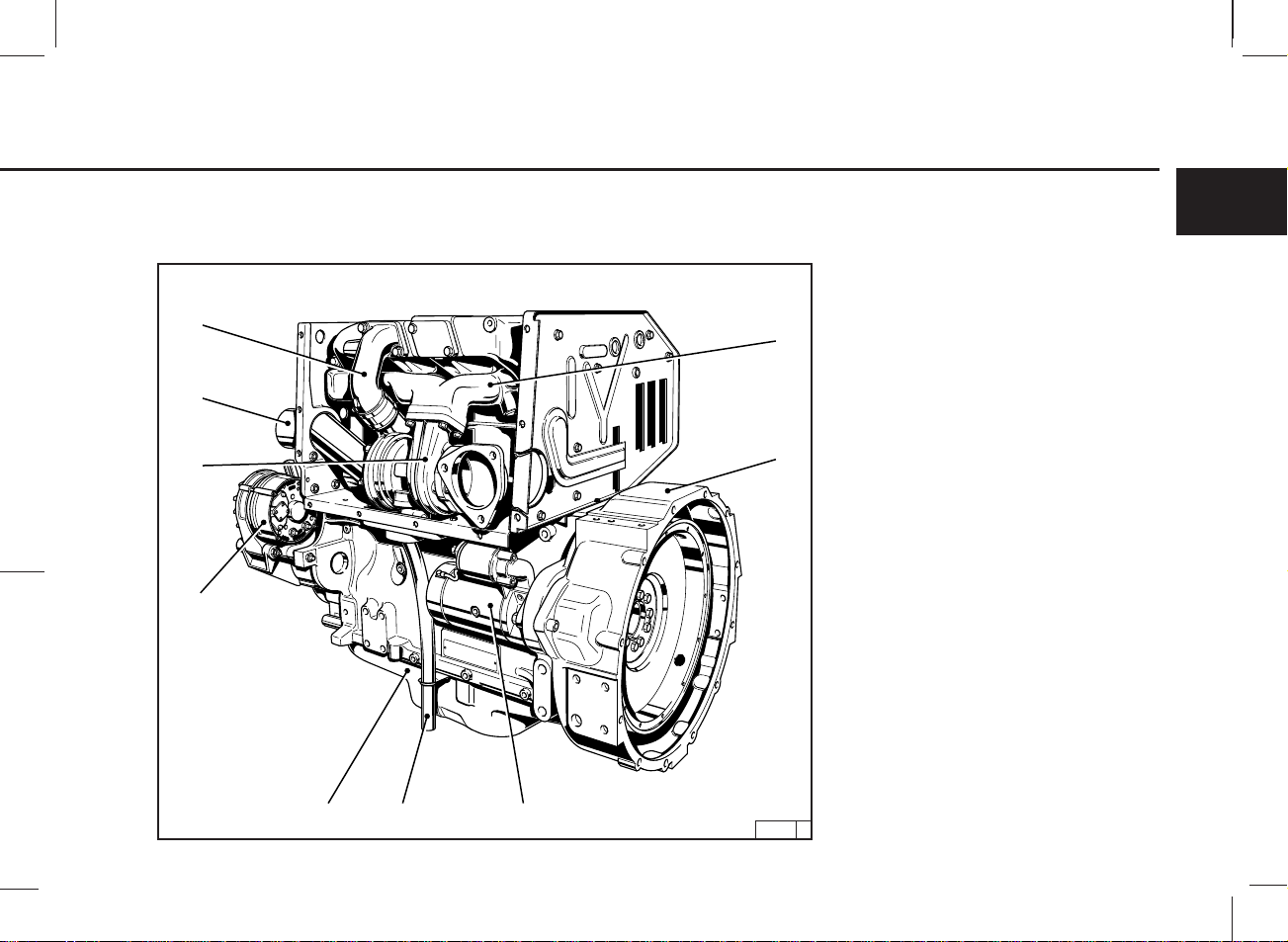
Engine Description 2.2 Engine Illustrations
2.2.1 Service Side
2
15
14
13
12
F4L 912
1 Fan
2 V-belt (fan)
3 Injection pump
4 V-belt (alternator)
5 V-belt pulley
6 Tension roller
7 Oil fill point
8 Oil pan
1
2
9 Oil drain plug
10 Fuel pump
11 Oil dipstick
12 Lube oil filter
13 Easy-change fuel filter
14 Air duct cover
15 Cylinder-head cover
3
4
5
12
12
6
7891011
24 856 2
2.2 Engine Illustrations Engine Description
2.2.2 Exhaust Side
F4L 912
16
17
18
19
20
21
22
2
16 Air-intake pipe
17 Exhaust manifold pipe
18 Screen
19 Alternator
20 Starter
21 Engine mounting
22 Crankcase
23 Crankcase ventilation
13
23
24 857 1
13 Gerade
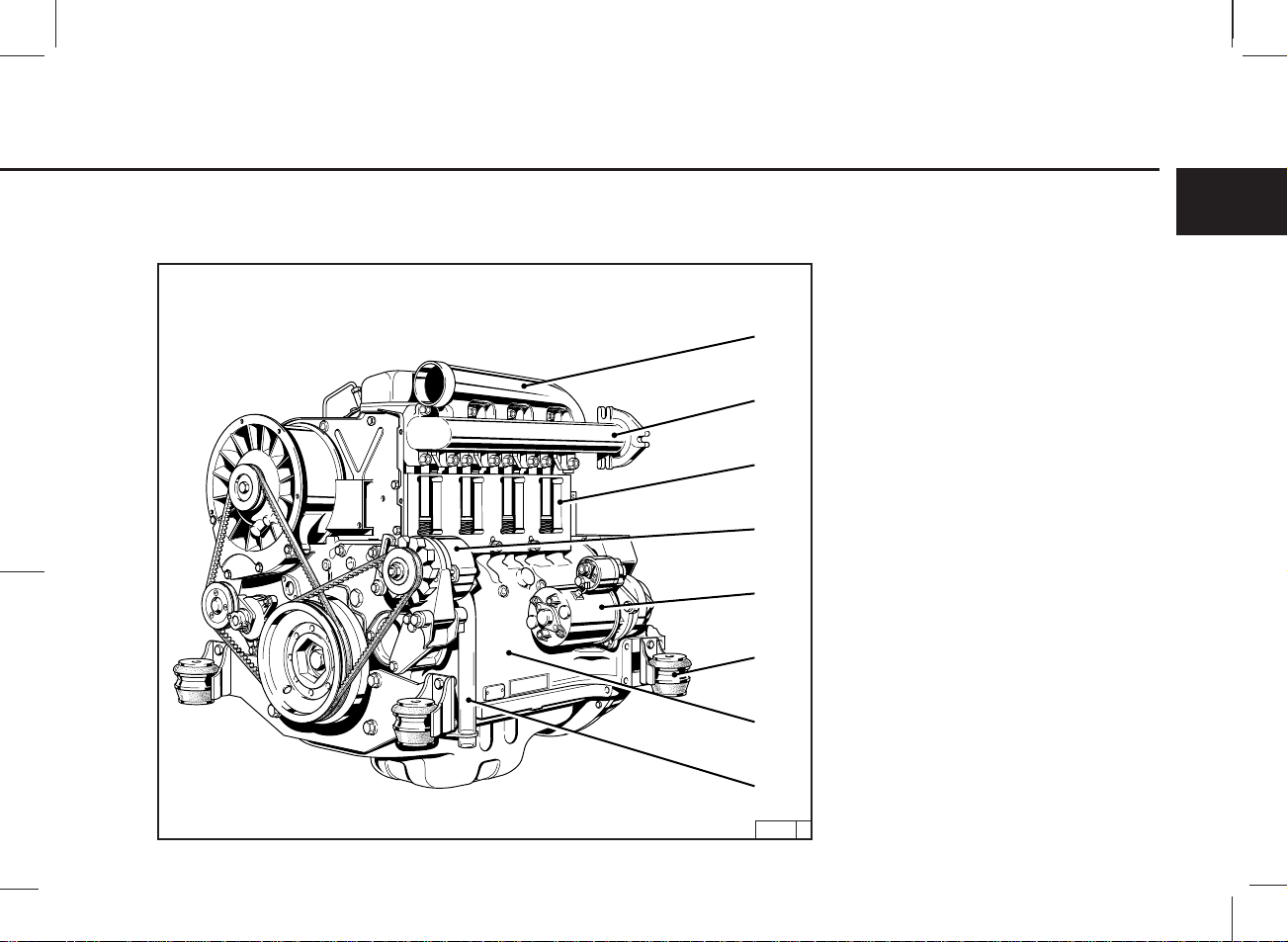
Engine Description 2.2 Engine Illustrations
2.2.3 Service Side
2
14
13
12
BF4L 913
1 Fan
1
2
3
2 V-belt (fan)
3 V-belt (alternator)
4 V-belt pulley on crankshaft
5 Tension roller
6 Oil fill point
7 Oil drain plug
8 Fuel filter cartridge
9 Fuel pump with fuel precleaner
10 Injection pump
11 Oil dipstick
12 Lube oil filter cartridge
13 Air duct cover
14 Engine oil radiator cover
4
11
14
14
6578910
30016 0
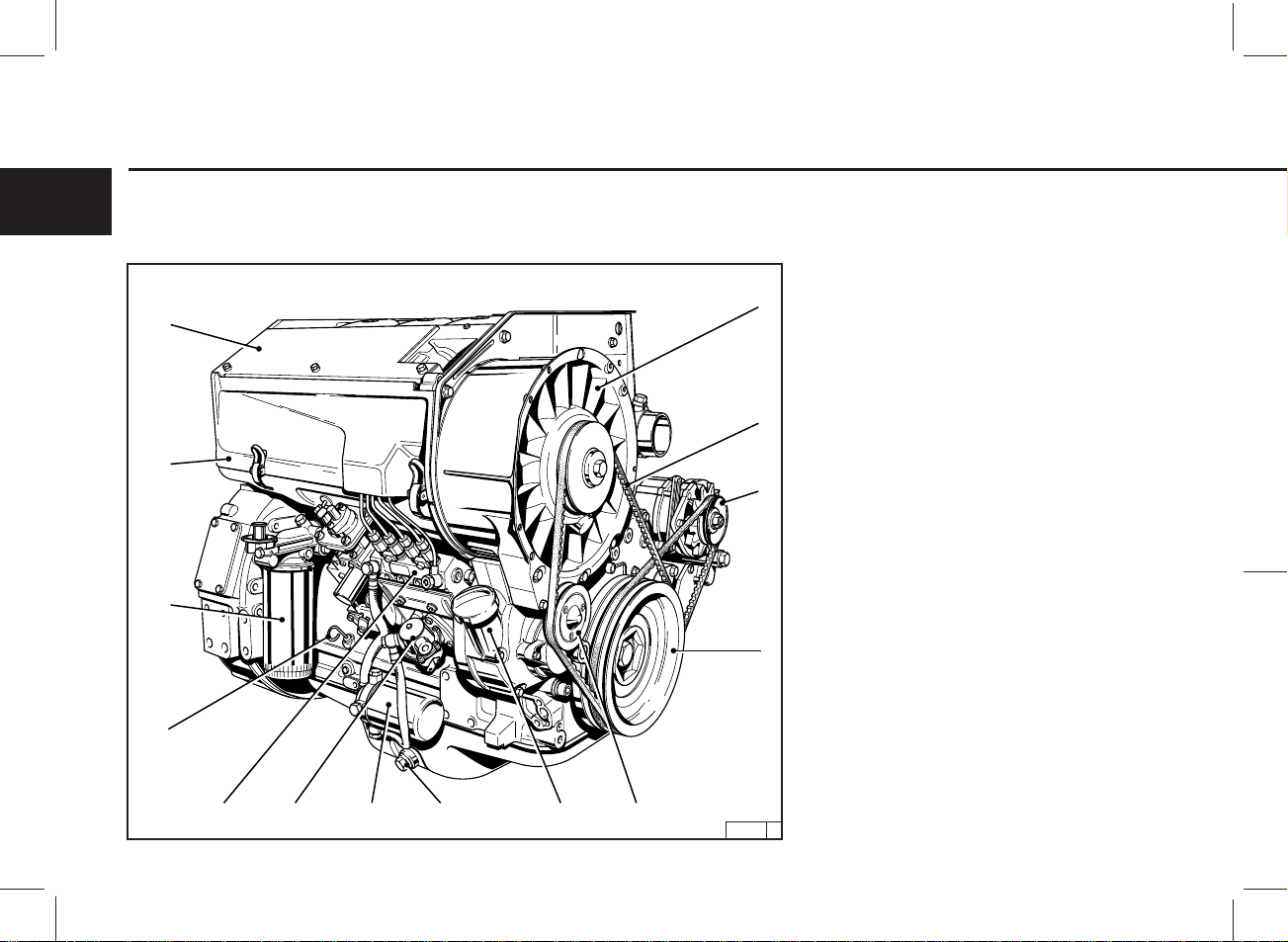
2.2 Engine Illustrations Engine Description
2.2.4 Exhaust Side
BF4L 913
23
22
21
20
15
16
2
15 Exhaust manifold line
16 Terminal housing
17 Starter
18 Crankcase ventilation
19 Oil pan
20 Alternator
21 Exhaust turbocharger
22 Air-intake pipe-exhaust turbocharger
23 Charge-air line
15
171819
30017 0
15 Gerade
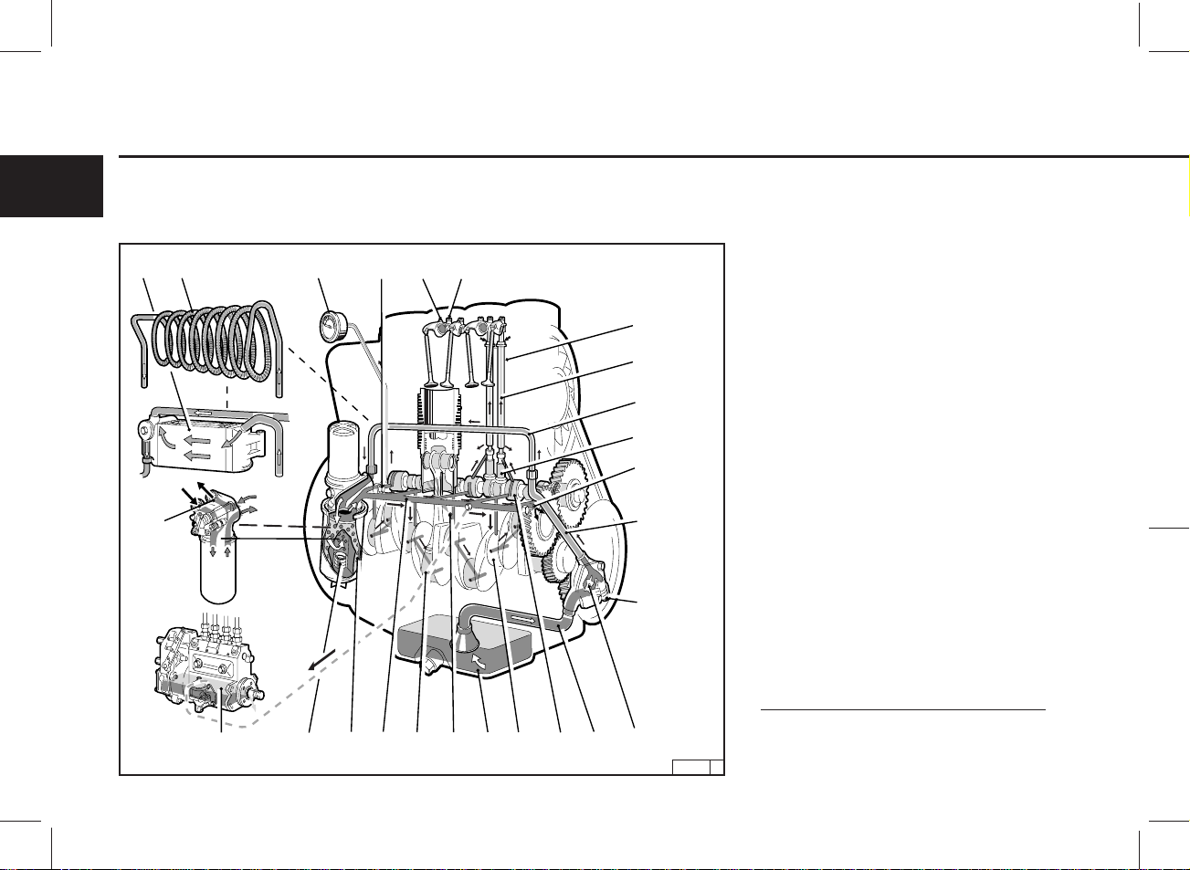
Engine Description 2.3 Lube Oil Circuit
2.3.1 Lube Oil Circuit
2
25
FL 912 / 913
1 Oil pan
1718222378
19
16
6
15
20
5
4
2 Intake manifold
3 Oil pump
4 Oil pressure control valve
5 Pressure-oil line
6 Bypass line or selectively
7 Finned pipe spiral or selectively
8 Frame oil cooler
9 Lube oil filter
10 Safety valve
11 Main oil gallery
12 Crankshaft bearing
13 Con-rod bearing
14 Camshaft bearing
15 Tappets
16 Push rod (hollow, for oil feed to rocker arm
lubrication)
17 Rocker arm bearing
18 Metering plug (
19 Protective sleeve for push rod
20 Throttle bore (for lubrication of the gear wheels)
21 Injection jet for cooling the pistons
22 Connection for oil pressure gauge
23 Oil pressure gauge
24 Injection pump connected to lube oil circuit
25 Connection point for oil heating**
r. arm lubrication
)*
16
16
24
10 9 11 13 21 1 12 14 2 3
19 058 6
* only for inclined engines
** in this instance the filter holder must
be replaced. Please contact our service
representative for this alteration.
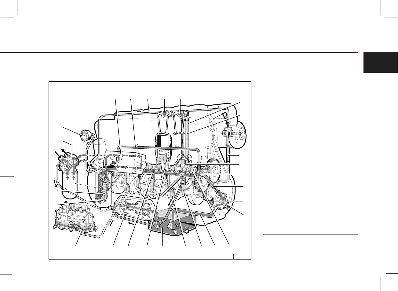
2.3 Lube Oil Circuit Engine Description
2.3.1 Lube Oil Circuit
BF6L 913
23
25
8
9
2
1 Oil pan
2 Intake manifold
2167
1617
18
15
22
14
19
5
3
4
21112120102426 13
24 355 2
3 Oil pump
4 Oil pressure control valve
5 Pressure-oil line
6 Connecting line to oil cooler
7 Frame oil cooler
8 Lube oil filter
9 Safety valve
10 Main oil gallery
11 Crankshaft bearing
12 Con-rod bearing
13 Camshaft bearing
14
Tappets (with impulse lubrication of the rocker arm)
15
Push rod (hollow, for oil feed to r. arm lubrication)
16 Rocker arm bearing
17 Metering plug (
18 Protective sleeve for push rod (oil return from
cylinder head to crankcase)
19 Throttle bore (for lubrication of the gear wheels)
20 Injection jet for cooling the pistons
21 Oil line for lub. of the exhaust turbocharger
22
Oil ret. line from exhaust turboc. to the crankcase
23 Oil pressure gauge
24 Partial-flow lube oil filter
25 Connection point for oil heating**
26 Injection pump connected to lube oil circuit
* only for inclined engines
** in this instance the filter holder must be
replaced. Please contact our service represen-
tative for this alteration.
r. arm lubrication
)*
17
17 Gerade
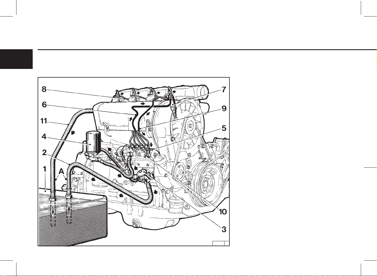
Engine Description 2.4 Fuel System Schematic
2.4.1 Fuel Circuit
2
1 Fuel tank
2 Fuel line from tank to fuel pump
3 Fuel supply pump
4 Easy-change fuel filter
5 Injection pump
6 Injection lines
7 Injection valves
8 Oil leakage line
9 Fuel overflow pipe
10 Overflow valve
11 Fuel return line to tank
A Clearance: keep as far apart as possible
18
18
24 673 3
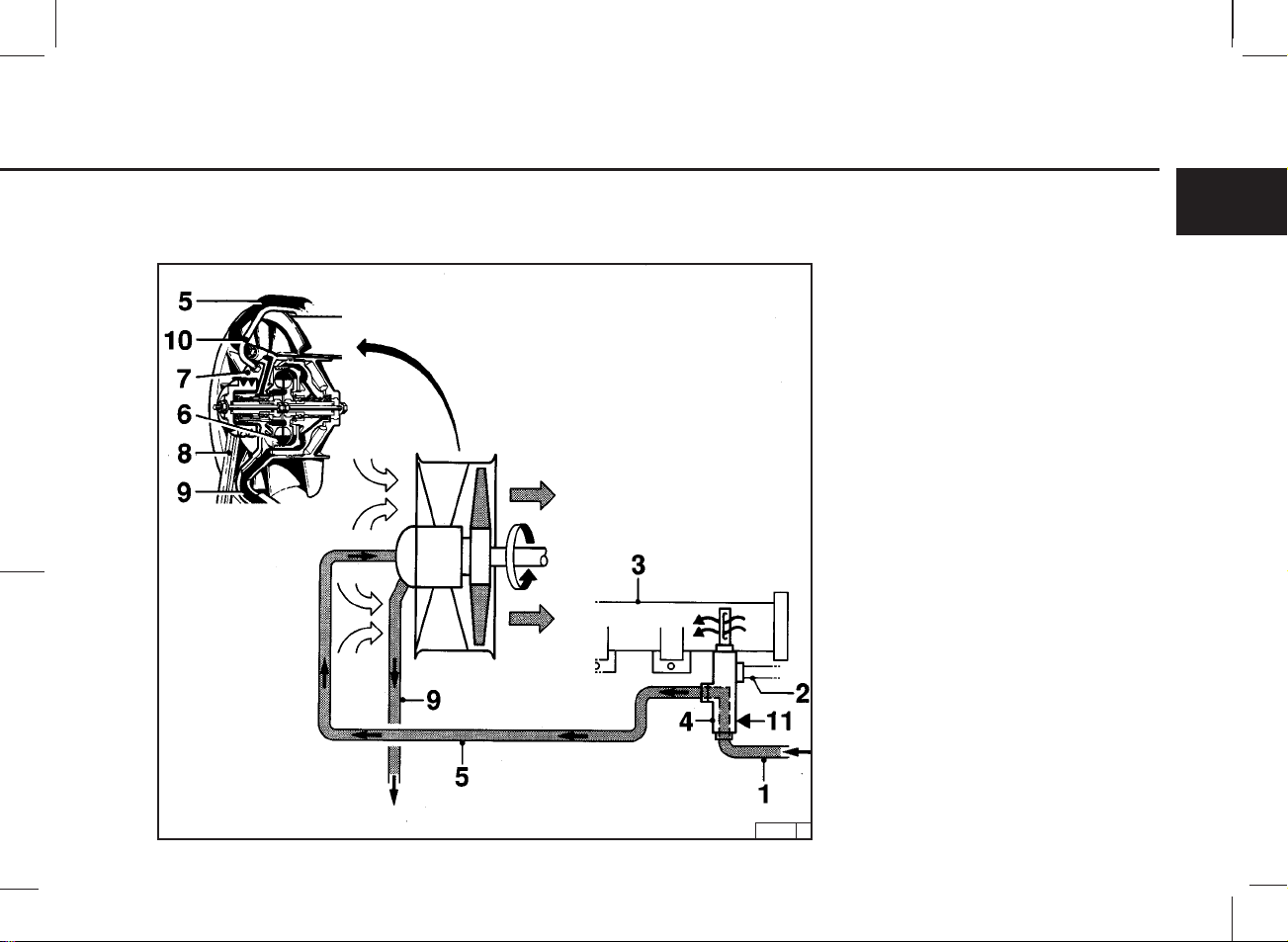
2.5 Engine Cooling Engine Description
2.5.1 Regulation of Coolant Flow using the Exhaust Thermostat
2
1 Pressure-oil line from engine to exhaust
thermostat
2 Air line to exhaust thermostat
3 Exhaust manifold pipe
4 Exhaust thermostat
5 Control line to hydraulic coupling
6 Hydraulic coupling
7 Cooling fan
8 Cooling fan drive
9 Oil return line to crankcase
10 Ventilation line
11 Adjusting pin with special seal
19
26 120 1
19 Gerade
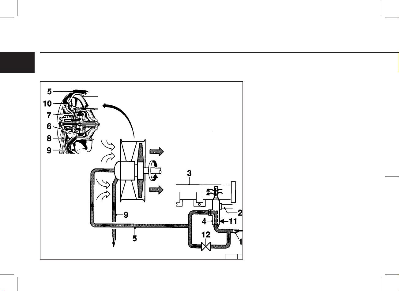
Engine Description 2.5 Engine Cooling
2.5.2 Regulation of Coolant Flow using the Exhaust Thermostat and Solenoid
2
1 Pressure-oil line from engine to exhaust
thermostat
2 Air line to exhaust thermostat
3 Exhaust manifold pipe
4 Exhaust thermostat
5 Control line to hydraulic coupling
6 Hydraulic coupling
7 Cooling fan
8 Cooling fan drive
9 Oil return line to crankcase
10 Ventilation line
11 Adjusting pin with special gasket
12 Solenoid
20
20
26 121 0

3.1 Commissioning
3.2 Starting
3.3 Monitoring Systems
3.4 Stopping
3.5 Operating Conditions
Engine Operation
3
21
Engine Operation 3.1 Commissioning
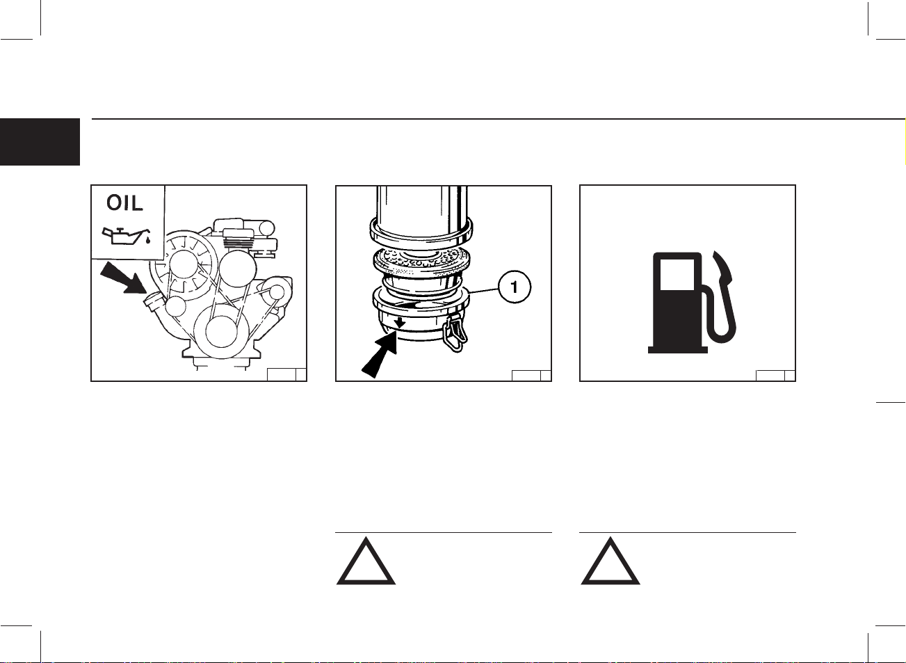
3.1.1 Adding Engine Oil 3.1.2 Filling Oil Bath Air Cleaner 3.1.3 Adding Fuel
3
FUEL
24 675 1
As a rule, engines are delivered empty of oil.
Pour lube oil into the oil filler neck (arrow).
For oil grade and viscosity, see 4.1
24 980 2
Fill oil cup 1 of the oil bath air cleaner with engine
oil up to the arrow.
For oil grade and viscosity, see 4.1
Oil may not be filled into the dust
collector of the precleaner, if this is
fitted.
! !
26 398 0
Use only commercial-grade diesel fuel. For fuel
grade, see 4.2. Use summer or winter-grade fuel,
depending on the ambient temperature.
Never fill the tank while the engine
is running. Keep the filler cap area
clean and do not spill fuel.
3.1 Commissioning Engine Operation
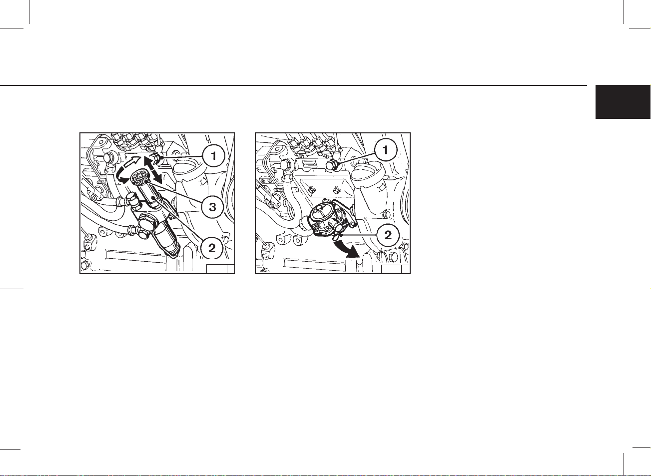
3.1.4 Ventilation
Model:
“Bosch” fuel pump
24 593 1 24 592 1
● Loosen overflow valve 1 at the lower (larger)
hexagon.
● Loosen hand pump 2 at the notched grip 3 by
unscrewing by several turns to the left.
● Actuate hand pump 2 until bubble-free fuel is
emitted at the loosened overflow valve 1.
● Tighten overflow valve 1, continuing to pump at
the same time.
● Tighten grip 3.
Ventilation
Model:
“IMSA” fuel pump
● Loosen overflow valve 1 at the lower (larger)
hexagon.
● Actuate preliminary pump lever 2 against the
spring pressure until bubble-free fuel is emitted
at the loosened overflow valve 1.
● Tighten overflow valve 1, continuing to pump at
the same time.
3
23
Engine Operation 3.1 Commissioning
3.1.5 Other Preparations
3
● Check battery and cable connections, see 6.7.1
● Transport hooks
Remove if fitted (see 6.7.3).
● Trial run
After the engine has been prepared, let it run for
about 10 minutes without load.
During and after trial run
– Check the engine for leaks.
After the engine has been turned off
– Check the oil level, see 6.1.2
If necessary, top up oil, see 3.1.1
Retension V-belts, see 6.5
● Breaking in
During the break-in phase – about 200 operating
hours – check the oil level twice a day. After the
engine is broken in, checking once a day will be
sufficient.
3.1.6 Additional Maintenance Work
The following maintenance should be carried out
after 50-150 operating hours:
● Change lube oil,
see 6.1.2
● Change oil filter cartridge,
see 6.1.3
● Change fuel filter cartridge,
see 6.2.1
● Check V-belts and retension as necessary,
see 6.5
● Check valve clearance and adjust as necessary,
see 6.6.1
● Check the engine for leaks.
● Check the engine mount and adjust as necessary,
see 9.2
3.1.7 Selector Switch for Oil Heater
30 027 0
Position of selector switch for oil filter console with
oil heater connection:
Pos. 1: open
Pos. 2: closed
For engines without oil heating, the
selector switch is always open
Pos. 2: to lock closed.
!

3
25

Engine Operation 3.2 Starting
3.2.1 Electric Starting
3
Before starting, make sure that
nobody is standing in the immediate
vicinity of the engine or driven
machine.
!
After repair work:
replaced and that all tools have been removed from
the engine.
When starting with flame glow system, do not use
any other starter substance (e.g. injection with start
pilot).
Caution: If the speed regulator has been removed,
the engine must not be tested under any circumstances:
Disconnect the battery.
Check that all guards have been
24 627 2 25 746 2
Starting without Cold-Start Aid
Do not actuate the starter for more than 20 seconds.
If the engine does not catch, wait a minute then try
again.
If the engine does not catch after two attempts,
refer to the Diagnosis Chart (see 7.1).
● Where possible, disengage the clutch to separa-
te the engine from any driven parts.
● Move speed control lever 1 into idle position.
● Insert key.
– Position 0 = no operating voltage
● Turn key clockwise
– Position 1 = operating voltage
– Pilot lights come on.
● Push the key in and turn it further clockwise
against spring pressure
– Position 2 = no function
– Position 3 = start
● Release key as soon as engine fires
– Pilot lights go out.

3.2 Starting Engine Operation
with Cold-Start Aid/Flame Glow Plug
FR 60 = 9.5 and 19 volts
25 746 2
● Insert key.
– Position 0 = no operating voltage.
● Turn key clockwise.
– Position 1 = operating voltage
– Pilot lights come on.
● Push key in and turn further clockwise against
spring pressure.
– Glow plug indicator comes on.
– Position 2 = Preheat for approx. 60 seconds
(hold key in position)*.
– Glow plug indicator goes out.
– Position 3 = start
● Release key as soon as engine fires.
– Pilot lights go out.
* By afterignition in position 2 for up to approx. 3
mins, it is possible to lower further the exhaust
gas opacity in the revving-up phase.
with Cold-Start Aid/Flame Glow Plug
FR 20/30 = 11 and 23 volts
25 746 2
● Insert key.
– Position 0 = no operating voltage
● Turn key clockwise.
– Position 1 = operating voltage
– Pilot lights come on.
● Push key in and turn further clockwise against
spring pressure.
– Glow plug indicator comes on.
– Position 2 = Preheat for approx. 20 -30 seconds
(hold key in position)*.
– Glow plug indicator goes out
– Position 3 = start
● Release key as soon as engine fires
– Pilot lights go out.
* By afterignition in position 2 for up to approx. 3
mins, it is possible to lower further the exhaust
gas opacity in the revving-up phase.
with heating pipe
25 746 2
● Insert key.
– Position 0 = no operating voltage.
● Turn key clockwise.
– Position 1 = operating voltage
– Pilot lights come on.
● Push key in and turn further clockwise against
spring pressure.
– Position 2 = Preheat for approx. 60 seconds
(hold key in position)*.
– Position 3 = start
● Release key as soon as engine fires
– Pilot lights go out.
* By afterignition in position 2 for up to approx. 3
mins, it is possible to lower further the exhaust
gas opacity in the revving-up phase.
3
27

Engine Operation 3.3 Monitoring Systems
3.3.1 Engine Oil Pressure
3
Oil Pressure Pilot Light
Oil Pressure Indicator Oil Pressure Gauge
● The oil pressure pilot light comes on with
operating voltage on and engine off.
● The oil pressure pilot light should go out when
the engine is running.
9690en_K03 21.08.2000, 11:36 Uhr28
25 752 1
● The pointer must remain in the green sector over
the entire range.
25 754 025 753 0
● The pointer must indicate the minimum oil
pressure (see 9.1).

3.3 Monitoring Systems Engine Operation
3.3.2 Engine Temperature
Temperature Gauge
24 985 0
● The engine temperature gauge pointer should
remain in the green sector most of the time. It
should rarely enter the yellow-green sector. If the
pointer enters the orange sector, the engine is
overheating. Turn off and establish the cause
from the Diagnosis Chart (see 7.1).
3.3.3 Cooling Fan Drive
3
24 590 1
● If the V-belt rips, pressure pin 1 of the electrical
switch is actuated by the tension roller and an
acoustic or light signal is given.
Switch off the engine immediately to prevent
overheating.
29
9690en_K03 21.08.2000, 11:35 Uhr29

Engine Operation 3.4 Stopping
3.4.1 Mechanical Shutdown 3.4.2 Electrical Shutdown
3
Ignition Key
24 630 1
● Move speed control lever 1 to low idle.
● Operate shutdown lever 2 until the engine comes
to a stop. The charge pilot light and the oil
pressure pilot light will come on when the engine
stops.
● Turn key anticlockwise (to position 0) and remove.
The pilot lights will go out.
25 746 2
● Turn key anticlockwise (to position 0) and remove.
The pilot lights will go out.
If possible, do not suddenly switch off the engine
when under full load.

3.5 Operating Conditions Engine Operation
3.5.1 Winter Operation
● Lube Oil Viscosity
– Select the oil viscosity (SAE grade) according
to the ambient temperature when the engine is
started, see 4.1.2
– Increase oil change frequency when operating
below -10 °C, see 6.1.1
● Diesel Fuel
– Use winter-grade diesel fuel for operation below
0 °C, see 4.2.2
● Additional Maintenance Work
– Drain the sludge from the fuel tank once a
week. (Unscrew the sludge drain plug.)
– If necessary, allow the oil in the oil bath air
cleaner and the engine oil to settle at the
ambient temperature.
– Below -20 °C, after removing the starter if
necessary, smear the ring gear on the fly wheel
via the pinion bore from time to time with coldresistant grease
(e.g. Bosch grease FT 1 V 31).
● Cold-Start Aid
– At temperatures near or below freezing point,
use glow plugs if necessary, see 3.2.1. This not
only lowers the starting limit temperature, but
provides easier starting at temperatures normally not requiring a starting aid.
3
● Battery
– Efficient cold starting requires a healthy battery,
see 6.7.1
– The starting limit temperatures can be lowered
by 4-5 °C by heating the battery up to about
+20 °C. (To do so, remove the battery and store
in a warm place.)
26 248 0
31

Engine Operation 3.5 Operating Conditions
3.5.2 High Ambient Temperatures,
3
High Altitude
● As the altitude and ambient temperature rise, the
density of air tends to decrease, which affects
the maximum power output of the engine, the
exhaust gas quality and, in extreme cases, the
starting behaviour. Under transient conditions,
the engine can be used at altitudes up to 1000 m
and temperatures up to 30 °C. If the engine is to
operate under more severe conditions (at higher
altitudes or temperatures), it will be necessary to
reduce the injected fuel quantity and thus, engine
power.
● If you have any doubts about engine operation
under these or similar conditions, ask your engine
or equipment supplier whether the engine has
been derated in the interests of reliability, service
life and exhaust gas quality (smoke). Otherwise
contact DEUTZ SERVICE.
C F
0 32
25 901 1

4.1 Lube Oil
4.2 Fuel
Operating Media
4
33
33 Gerade33 Gerade

Operating Media
4.1.1 Quality grade 4.1.2 Viscosity
4
4.1 Lube Oil
Lube oils are differentiated according to their
performance and quality class. In common use are
specifications named after the API (American Petroleum Institute) and ACEA (European Engine Oil
Sequences).
Approved API Oils:
At least: CD
Approved ACEA Oils:
At least: E1-96
Oil change intervals, see 6.1.1
Oil capacities, see 9.1
As the viscosity of the lube oil is dependent on
temperature, the choice of SAE grade should be
governed by the ambient temperature prevailing at
the engine operating site. Optimum operating
behaviour will be attained if you take the accompanying oil viscosity diagram as a guide.
Should the temperature fall temporarily below the
limits of SAE grade selected, cold starting may be
affected but the engine will not be damaged.
In order to keep wear to a minimum, do not exceed
application limits for extended periods of time.
Oil changes dictated by the seasons can be avoided
by using multi-grade lube oils. Multi-grade oils –
particularly light-flowing oils – also reduce fuel
consumption.
- 13
- 22
-31
- 40
° C
° F
86
+ 30
77
+ 20
68
59
50
+ 10
41
SAE 10W/40
SAE 15W/30
SAE 15W/40
32
+ 0
23
14
- 10
5
- 4
- 20
- 30
- 40
SAE 10W/30
SAE 5W/30 (Synthetic)
✳
SAE 40
SAE 30
SAE 20W/20
26021 0
✳ nur mit Motorvorwärmung
*only with engine oil preheating
*Seulement avec préchauffe du moteur
34 34 34

4.2 Fuel Operating Media
4.2.1 Quality Grade 4.2.2 Winter-Grade Fuel
Use commercially available diesel fuel with less
than 0.5 % sulphur content. If the sulphur content
is higher than 0.5 % oil change intervals should be
reduced, see 6.1.1
The following fuel specifications / standards are
approved:
● DIN EN 590
● BS 2869: A1 and A2
(with A2, take note of the sulphur content!)
● ASTM D 975-88; 1-D and 2-D
● NATO Code F-54 and F-75
Any exhaust emission levels which may have been
determined during type approval tests always refer
to the reference fuel prescribed by the authorities
for the type approval test.
Waxing may occur at low temperatures, clogging
the fuel system and reducing engine efficiency. If
the ambient temperature is less than 0 °C, wintergrade fuel (suitable down to -15 °C) should be used.
(This fuel is usually available from the filling stations
well in advance of the cold months). Diesel fuel
containing additives (Super diesel) is often on sale
as well, for use down to -20 °C.
● Below -20 °C, petroleum must be added. For the
required mixing ratios please refer to the adjacent
diagram.
● For artic climate zones down to -44 °C special
diesel fuels can be used.
If summer-grade diesel fuel must be used at
temperatures below 0 °C, up to 60% kerosene can
be added (see diagram).
In most cases, adequate resistance to cold can be
obtained by adding a flow improver (additive).
Please inquire at DEUTZ-PARTNER.
0
+32
+23
- 5
+14
- 10
+ 5
- 15
- 20
- 4
- 25
- 13
- 22
- 30
°F
°C
Legend:
I Summer diesel fuel
II Winter diesel fuel
A Ambient
B Proportion of Kerosene to be
II
0 10 20 30 40 50 60 %
A
I
4
B
26441 1
35
Mix in tank only. Fill with the
appropriate amount of kerosene
first, then add the diesel fuel.
!
35 Gerade35 Gerade

4
36 36 36

Routine Maintenance
5.1 Maintenance Schedule
5.2 Maintenance Charts
5.3 Maintenance Work Completed
5
37
37 Gerade37 Gerade

Routine Maintenance 5.1 Maintenance Schedule
5
Once
every
after
10 OH
2)
or
50-150
daily
●
●
●
●
●●●
● ●●●
●●
●●
●●●
●●
●●
●
●●
Operating hours (OP)
every
●
●
1)
2000 3000 50001000500250125
●
●
●
check
clean
change
Operation
●
●
●
●
●
●●
●
●
●
●
●
●
●
●
Oil level in engine / separate container 6.1.2
Engine leaks
Oil bath- and dry type air cleaners 3) 4) 6.3/6.4
Battery and cable connectors 6.7.1
Cooling system (depending on engine use) 3) 6) 6.3.1/6.3.2
Engine oil (depending on engine use) 5) 6.1.1/6.1.2
●
Oil filter cartridge 6.1.3
●
Fuel filter cartridge 6.2.1
Valve clearance (adjust if necessary) 6.6.1
Engine mounts (retighten if necessary) 9.2
V-belts (retension if necessary) 6.5
Warning system 6.5.5
●
Fuel precleaner 6.2.2
Mountings 6.8.1
Flame glow plugs 4) 6.8.3
●
Partial-flow oil filter 6.1.4
Sheathed element heater plugs
Injection valve
See
Section
The specified engine maintenance times are maximum values. Depending on the operating environment, shorter maintenance intervals may be required. Please
observe the operating instructions of the equipment manufacturer.
1) Recommended maximum
2) Commissioning new or reconditioned engines
3) Clean if needed, see Section 6.3
4) Change if necessary. If fitted, service after service indicator.
5) Oil change interval, see Section 6.1.1
6) Clean system / cooling fins.
38 38 38
(Wartung Tab 5.1 BA 912/913 de)

5.2 Maintenance Charts Routine Maintenance
The maintenance charts shown here are supplied
as self-adhesive labels with each engine. They
should be affixed where they can be seen clearly on
the engine or driven equipment.
Check that this is the case.
If necessary, ask your engine or equipment supplier
for a fresh supply of labels.
Routine work should be carried out according to the
schedule in 5.1
Stop the engine before carrying out
any maintenance work.
!
in.
ex.
0297 7224
0,15 mm
a =
0.006 in
a
1000
1252000
F
U
1000
E
L
500 500
0
FL 912/913
O
IL
OIL
max.
h
Std.
ca.
1000
10
a
in.
ex.
OIL
OIL
max.
BF 4/6L 913/C/T
2
0297 4070
500
125-
2000
500
10
15 mm
0.6 in.
a =
10
250
250
500
0,15 mm
0.006 in
A
IR
OIL
1000 1000
FUEL
h
Std.
5
AIR
10
15 mm
ca.
0.6 in.
250
250
IL
O
500
39
Bildverkleinerung 65% x 65 % max Raster 117 breite 118 mm höhe
39 Gerade39 Gerade

Routine Maintenance 5.3 Completed Maintenance Jobs
5
Hours
50-150*
125
375
625
875
1125
1375
1625
1875
2115
2375
2625
* Commissioning new and overhauled engines.
The maintenance jobs duly completed can be recorded in the above table.
Date
Signature / Stamp
Date Signature / StampHours
–
250
500
750
1000
1250
1500
1750
2000
2250
2500
2750
40 40 40

5.3 Completed Maintenance Jobs Routine Maintenance
Hours
2875
3125
3375
3625
3875
4125
4375
4625
4875
5125
5375
5625
The maintenance jobs duly completed can be recorded in the above table.
Date
Signature / Stamp
Hours
3000
3250
3500
3750
4000
4250
4500
4750
5000
5250
5500
5750
Date
Signature / Stamp
5
41
41 Gerade41 Gerade

Routine Maintenance 5.3 Completed Maintenance Jobs
5
Hours
5875
6125
6375
6625
6875
7125
7375
7625
7875
8125
8375
8625
The maintenance jobs duly completed can be recorded in the above table.
Date
Signature / Stamp
Hours
6000
6250
6500
6750
7000
7250
7500
7750
8000
8250
8500
8750
Date
Signature / Stamp
42 42 42

Service and Maintenance
6.1 Lubrication System
6.2 Fuel System
6.3 Cooling System
6.4 Combustion Air System
6.5 Belt Drives
6.6 Adjustments
6.7 Accessories
6.8 Engine Cleaning
6.9 Additional Maintenance
6
43
9690en_K06_1 21.08.2000, 11:40 Uhr43
43 Gerade43 Gerade

Service and Maintenance 6.1 Lubrication System
6.1.1 Oil Change Intervals
6
● The oil change intervals are dependent on the
engine application and the quality of the lube oil.
● If the engine runs fewer hours during the year
than stated in the table, the oil should be changed
at least once a year.
● The table refers to the following conditions:
– For diesel fuel: sulphur content max. 0.5% by
weight.
– Continuous ambient temperatures down to
-10 °C (+14 °F).
● If the sulphur content is > 0.5 to 1% or the
continuous ambient temperature below -10 °C
(+14 °F), the intervals between oil changes should
be halved.
● In the case of fuels containing more than 1%
sulphur, contact your service representative.
Change the oil with the engine off but still warm
(lube oil temperature approx. 80 °C).
Installed engines
Lube oil quality
Normal oil usage, e.g.:
Road vehicles, cranes, construction
machinery, ships, electrical units, pumps,
rail-run vehicles
Heavy-duty oil usage, e.g.:
Combine harvesters, emergency pumps, underground
sweeping machines, winter operation equipment, emergency
power generating units
Vehicle engines
Lube oil quality
Service group
II
III
API classification
ACEA classification
API classification
ACEA classification
Annual kilome
trage km
30 000 – 100 000
< 100 000
equipment,
average speed
approx km/h
40
60
Lube oil intervals in OH
Naturally aspirated engines
CF-4/CH-4/CG-4 CF-4
E1-E3/96+ E4-98 E1-E2/96
500 250 500
250
Lube oil intervals in km
Naturally aspirated engine
CF-4/CH-4/CG-4 CF-4
E1-E3/96+ E4-98 E1-E2/96
10 000 5 000 10 00020 > 30 000I
20 000
30 000
Turbocharged engines
CH-4/CG-4
E3-96+ E4-98
125 250
Turbocharged engine
CH-4/CG-4
E3-96+ E4-98
10 000
15 000
20 000
30 000
44 44 44
44
9690en_K06_1 21.08.2000, 11:40 Uhr44

6.1 Lubrication System Service and Maintenance
6.1.2 Checking Oil Level /
Changing Engine Oil
6.1.2.1 Checking Oil Level 6.1.2.2 Engine Oil Change
● Ensure that the engine or vehicle is in a horizon-
tal position.
● – Warm engine:
Switch off engine, wait 5 minutes and check the
öil level.
● – Cold engine:
Check oil level.
To this end:
● Remove the oil dipstick.
● Wipe the dipstick with a non-fibrous, clean cloth.
● Insert it to the stop and remove again.
● Check the oil level, and if necessary, top up to the
“MAX” mark.
– If the oil level is only just above the “MIN”
mark, more oil must be added.
The oil level must not fall below the “MIN” marking.
● Ensure that the engine or vehicle is on a level
surface.
● Allow the engine to warm up
– Lube oil temperature approx. 80°C.
● Switch off the engine.
6
26 022 0 25 729 0
● Place oil tray under the engine.
● Unscrew drain plug.
● Drain oil.
● Fit oil drain plug, with the new gasket and tighten
firmly (for torque, see 9.2).
● Fill with lube oil.
– For grade / viscosity, see 4.1
– For quantity, see 9.1
● Check oil level, see 6.1.2.1
Be careful when draining hot oil – danger
of scalds! Do not let used oil run into the
!
soil but catch it in a container ready for
proper disposal.
26 023 0
45
9690en_K06_1 21.08.2000, 11:41 Uhr45
45 Gerade45 Gerade

Service and Maintenance 6.1 Lubrication System
6.1.3 Changing Oil Filter
6
● Undo the filter cartridge using a commercial tool
and spin off.
● Catch any dripping oil.
Beware of burns from hot oil.
!
46 46 46
9690en_K06_1 21.08.2000, 11:41 Uhr46
25881 0
● Clean any dirt from the filter carrier rim.
● Lightly oil the rubber gasket of the new oil filter
cartridge.
● Screw in the new cartridge finger tight against
the gasket.
25882 025880 0
● Tighten the oil filter cartridge with another half-
turn.
● Check oil level, see 6.1.2
● Check oil pressure, see 3.3.1
● Check cartridge seal for leaks.

6.1 Lubrication System Service and Maintenance
6.1.4 Changing the Partial-Flow Oil
Filter Insert
24 511 1
● Unscrew oil drain plug 1 and drain off oil.
● Unscrew tension screw 2. Remove the cover.
● Unscrew the dirtied filter insert 3. Clean the filter
housing.
● Check and if necessary replace cover seal 4.
● Screw in oil drain plug 1 with new seal 5.
● Fit new filter insert.
● Screw on cover with sealing ring 6.
● Check for leaks and check the oil pressure during
a test run.
6
47
9690en_K06_1 21.08.2000, 11:41 Uhr47
47 Gerade47 Gerade

Service and Maintenance 6.2 Fuel System
6.2.1 Changing Fuel Filter
6
● Close fuel stopcock.
● Undo fuel filter cartridge with commercial tool
and spin off.
● Catch any fuel.
Keep naked flames away when
working on the fuel system. Do not
smoke.
!
48 48 48
9690en_K06_1 21.08.2000, 11:41 Uhr48
25880 0
25881 0
● Clean any dirt from the filter cartridge with a final
half-turn.
● Apply light film of oil or diesel fuel to the rubber
gasket of the new fuel filter cartridge.
● Screw in the new cartridge finger tight against
the gasket.
25882 0
● Tighten the fuel filter cartridge with a final half-
turn.
● Open fuel stopcock.
● Check for leaks.
The fuel system does not need to be bled.

6.2 Fuel Filter Service and Maintenance
6.2.2 Fuel Precleaner
Cleaning the Fuel Filter
“Bosch” model
19 725 2
● Close the fuel shut-off valve.
● Loosen tensioning nut 2.
● Swing wire clip 1 to the side.
● Remove filter cone 5 with strainer 4 and clean in
fuel.
● Use a new seal 3 for filter cone 5.
● Bleed the fuel system, see 3.1.4
● Check for leaks.
Cleaning the Fuel Filter
“IMSA” model
1
2
3
4
26 047 1
● Close the fuel shut-off valve.
● Loosen hexagonal nut 1 and unscrew with sealing
ring 2.
● Remove cover 3.
● Remove fuel strainer 4.
6
● Clean the fuel strainer 4 in fuel. Replace if
necessary.
● Refit in the reverse order.
● Bleed fuel system, see 3.1.4
● Check for leaks.
No naked flames when working on
the fuel system.
No smoking!
!
49
9690en_K06_1 21.08.2000, 11:41 Uhr49
49 Gerade49 Gerade

Service and Maintenance 6.3 Cooling System
6.3.1 Cleaning Intervals
6
● The amount of contamination in the cooling
system depends on the engine application.
● Spilled oil or fuel on the engine increases the risk
of contamination. Be especially careful if the
engine is used in dusty environments.
● Serious contamination can occur, for example:
– on construction sites where there is a high
level of air-borne dust.
– in harvesting application where there are high
concentrations of chaff and chopped straw in
the vicinity of the machine.
● Because applications vary, cleaning intervals
have to be determined from case to case. The
cleaning intervals given in the table on the right
can be used as a guide.
Inspection and cleaning
intervals
Recommended
OH
2000
1000
500
250
125
Engine application
Ships, Electrical units in enclosed areas, pumps
Vehicles on reinforced highways
Tractors, fork-lift trucks, mobile electrical units
Vehicles on construction sites and on roads with loose surfaces,
constrution machinery, compressors, mining equipment
Agricultural machinery, tractors used for harvesting purposes
50 50 50

6.4 Combustion Air Filter Service and Maintenance
6.4.1 Cleaning Intervals
● The amount of dirt in the air cleaner depends on
the amount of dust in the air and the size of the
air cleaner used. If a high level of dust is
anticipated, a cyclone-type precleaner can be
fitted to the air cleaner.
● Cleaning intervals will have to be determined
from case to case.
● If dry-type air cleaners are used, they should be
cleaned only in accordance with the service
indicator or the service switch.
● Air cleaner servicing is needed when:
– Service indicator
the red signal 1 is fully visible when the
engine is off.
– Service switch
the yellow pilot light comes on when the
engine is running.
● After carrying out service work, reset the signal
by pressing the button on the service indicator.
6
25 885 1
51
51 Gerade51 Gerade

6.4 Combustion Air Filter Service and Maintenance
6.4.2 Emptying Cyclone Type
6
Precleaner
● Undo wing nut 1 and remove cover 2.
● Remove collector bowl 3 from lower section 4
and empty. Clean leaves, straw and other foreign
matter from lower section of precleaner.
● Reposition collector bowl 3 onto lower section 4,
fasten cover 2 in place by tightening wing nut 1.
6.4.3 Cleaning Oil Bath Air Cleaner
25 886 0 25 887 0
● Turn engine off and wait about 10 minutes for the
oil to drain from filter housing 1.
● Release snap clips 2 and remove oil cup 3
together with filter element 4. If necessary prise
element out with a screwdriver, taking care not to
damage the rubber gasket 5.
● Remove dirty oil and sludge. Clean oil cup.
● Clean filter element 4 in diesel fuel and allow to
drip-dry.
● Clean filter housing 1 if very dirty.
● Inspect and replace rubber gasket 5 and 6 if
necessary.
● Fill oil cup with engine oil up to the mark (arrow)
(for viscosity, see 4.1.2).
● Refit oil cup and element to filter housing and
secure with snap clips.
Never fill collector bowl with oil. Replace collector
bowl if damaged.
52 52 52
Never clean air cleaner with gasoline.
Dispose of cold oil in accordance
with environmental regulations!
!

6.4 Combustion Air Filter Service and Maintenance
6.4.4 Dry Type Air Cleaner
Dust Discharge Valve Filter Cartridges
25 888 1 25 889 0
● Empty dust discharge valve 1 by pressing apart
lips of discharge slot as indicated by arrows.
● Clean discharge slot from time to time.
● Remove any caked dirt by pressing together the
upper section of the valve.
● Undo clip fasteners 1.
● Take off hood 2 and remove cartridge 3.
● Clean cartridge (replace at least once a year).
● Clean cartridge 3.
Blow out from inside out with dry compressed
air (max. 5 bar), (or in difficult cases, tap out,
taking care not to damage the cartridge, or wash
according to manufacturer’s instructions).
● Through regular removal and replacement, the
gaskets on the filter cartridge can become
damaged. Check paper filter (light showing
through) and gaskets for damage. Replace if
necessary.
6
● After five cleaner services or after two years at
the latest, replace safety cartridge 4 (never clean).
To do so:
– Undo hex. nut 5 and remove cartridge 4.
– Install new cartridge, insert and tighten hex.
nut.
● Install cartridge 3, replace hood 2 and do up clip
fasteners 1.
Never clean filter cartridge with
gasoline or hot fluids.
!
53
53 Gerade53 Gerade

Service and Maintenance 6.5 Belt Drives
6.5.1 Checking V-Belts 6.5.2 Changing the Fan V-Belt
6
● Inspect entire V-belt for damage.
● Replace damaged V-belts.
● After installing new belts, run engine for 15
minutes, then check belt tension.
● To check the tension of the V-belt, use a tension
gauge (see 9.3).
– Place indicator arm 1 into gauge.
– Position gauge on V-belt 2, midway between
the pulleys, with flange 3 on bottom of gauge
against the edge of belt.
– Push slowly on the black pad 4 at right angles
to belt 2 until the spring is heard or felt to
trigger.
54 54 54
– Carefully remove the gauge without altering
the position of the indicator arm 1.
Read off the value where the black indicator
arm 1 intersects scale 5 (arrow). For
settings, see 9.1
– If necessary, retension belt and measure
again.
Check tension and change belts only
with the engine off. Refit belt guard,
if provided.
!
24 684 1
24 684 125 890 2
● To replace, press in tension roller 1 using a
commercial tool and remove the V-belts.
● Fit new V-belts.
When new V-belts are fitted, check the belt tension
after ca. 15 minutes running time.

6.5 Belt Drives Service and Maintenance
6.5.3 Tensioning Alternator Belts 6.5.5 Checking Warning System6.5.4 Changing Alternator Belts
26 051 1
● Loosen bolts 1, 2 and 3.
● Press alternator 4 outwards in direction of arrow
A until correct belt tension is achieved.
● Retighten bolts 1, 2 and 3.
● Remove fan V-belts as described under 6.5.2
● Loosen bolts 1, 2 and 3.
● Swing alternator 4 inwards in direction of arrow
B.
● Remove V-belts and place on new belt.
● Swing alternator 4 outwards in direction of arrow
A until correct belt tension is achieved.
● Retighten bolts 1, 2 and 3.
● Fit fan V-belts.
26 052 0
6
24 590 1
● If the V-belt rips, pressure pin 1 of the electrical
switch is actuated by the tension roller and an
acoustic or light signal is given.
● Functional check by pressing in pin 1.
55
Only check/tension/replace V-belts
when the engine is at a standstill. If
necessary, replace V-belt cover.
!
Retighten new V-belts after 15 minutes running
time.
Only carry out a check when the
engine is at a standstill.
!
55 Gerade55 Gerade

Service and Maintenance 6.5 Belt Drives
6.5.6 Tensioning and Changing Air
6
Compressor V-Belts
● Unscrew hexagonal bolts 1.
● Remove outer half of belt pulley 2.
● If necessary replace the V-belts.
56 56 56
9690en_K06_2.pm6 21.08.2000, 12:02 Uhr56
24 598 1
24 599 1
● To tighten, remove one or more of the inner
intermediate discs 3. Place the removed discs
on the removed half of the V-belt pulley 2.
● Retighten bolt 1. Whilst tightening, simulta-
neously rotate the engine to prevent the V-belt
from being crushed.
When new V-belts are fitted, check the belt tension
after ca. 15 minutes running time.

6.5 Belt Drives Service and Maintenance
6.5.7 Air Compressor Design with
Double V-Belt
20 762 2
● Screw off hexagonal nut 1, remove V-belt pulley
half 2, V-belt 3 and intermediate disc packet 7.
● Remove intermediate disc 4, rear V-belt 3,
intermediate disc packet 6 and V-belt disc half 5.
● To tighten, remove one or more of the in-
termediate discs from packet 6 or 7. Place the
removed discs in front of or behind V-belt pulley
halves 2, so that the V-belt remains aligned.
Always take the same number of discs from each
packet.
● Fit in the reverse order. Whilst tightening nut 1,
the engine must be rotated to prevent the V-belts
from being crushed.
If a V-belt is worn or damaged, both belts in the set
must be replaced. The difference in the length of the
new V-belts may not exceed 0.15%.
6
Only check or replace the V-belts when the engine
is at a standstill.
If necessary, replace the V-belt cover. When new Vbelts are fitted, check the belt tension after approx.
15 minutes running time.
57
57 Gerade57 Gerade

Service and Maintenance 6.6 Adjustments
6.6.1 Checking / Adjusting Valve
6
Clearances
19 691 2
● Remove the cylinder head cover.
● Position crankshaft as per schematic 6.6.1.1
● Before adjusting valve clearance, allow engine to
cool down for at least 30 minutes. The oil temperature should be below 80 °C.
● Check valve clearance 1 between rocker arm /
tappet contact face 2 and valve stem 3 with feeler
gauge 6 (there should be only slight resistance
when feeler blade is inserted).
For permissible valve clearance, see 9.1
Only inclined engines are fitted with an additional oil
jet for lubrication of the bearing. Any adjustments
must be carried out in an authorised specialist
workshop.
58 58 58
26 053 1
● Adjust valve clearance if necessary:
– Release locknut 4.
– Use screwdriver 7 to turn setscrew 5 so that
the correct clearance is attained after locknut 4
has been tightened.
● Check and adjust valve clearance on all remaining
cylinders.
● Replace cylinder head cover (use new gasket if
needed).

6.6 Adjustments Service and Maintenance
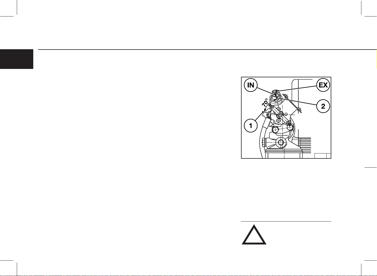
6.6.1.1 Valve Clearance
Adjustments Schematic
6
● Crankshaft Position 1:
Turn crankshaft until both valves in cylinder 1
overlap (exhaust valve about to close, inlet valve
about to open). Adjust clearance of valves marked
in black on schematic. Mark respective rocker
arm with chalk to show that adjustment has been
done.
● Crankshaft Position 2:
Turn crankshaft one full revolution (360°).
Adjust clearance of valves marked in black on
schematic.
59
26 055 1
59 Gerade59 Gerade

Service and Maintenance 6.7 Accessories
6.7.1 Battery
6
6.7.1.1 Checking Battery and
Cable Connectors
25 895 0 24 232 3 25 896 0
6.7.1.2 Checking Electrolyte Level 6.7.1.3 Checking Electrolyte
Density
● Keep battery clean and dry.
● Undo dirty clamps.
● Clean terminal posts (+ and -) and clamps of the
battery, and grease with acid-free and acidresistant grease.
● When reassembling, ensure that clamps make
good contact. Do up clamp bolts finger tight.
60 60 60
● Remove caps 1.
● If testers 2 are used, the electrolyte should come
up to their base.
● If testers are not used, the electrolyte level should
be 10-15 mm above the top of the plates.
● If necessary, top up with distilled water.
● Replace caps.
● Measure the electrolyte density of individual
cells with a commercial hydrometer.
The hydrometer reading (see table on following
page) indicates the state of charge.
During measurement, the temperature of the
electrolyte should preferably be +20 °C.

6.7 Accessories Service and Maintenance
6
in [kg/ l] in[°Bé (Baumégrad)*]
Normal Tropics Normal Tropics
1,28
1,20
1,12
* Measurement of electrolyte density in ° Bé (Baumégrad) is out of date and rarely used today.
!
Wear protective goggles. Do not rest tools on the
battery.
1,23
1,12
1,08
The gases emitted by the battery
are explosive! Keep sparks and
naked flames away from the battery.
Do not allow battery acid to come
into contact with skin or clothing.
32
24
16
27
16
11
State of Charge
Fully charged
Half charged, recharge
Discharged, recharge immediately
61
61 Gerade61 Gerade

Service and Maintenance 6.7 Accessories
6.7.2 Three-Phase Alternator 6.7.3 Lifting Tackle
6
Notes on the three-phase system:
● Never disconnect the cables between battery,
alternator and regulator while the engine is
running.
● If, however, it is necessary to start and operate
the engine without the battery, disconnect the
regulator from the alternator before starting.
● Be sure not to confuse the battery terminals.
● Replace defective bulb of the charge pilot lamp
immediately.
● When washing the engine, cover up the alternator
and regulator.
● The habit of touching a lead against the frame to
check whether it is live must under no circumstances be used with three-phase electrical
systems.
● In case of electric welding, connect the ground
terminal on the welder directly to the piece being
welded.
● Always use proper lifting tackle 1 when trans-
porting the engine.
● After transportation and before commissioning
of the engine: Remove transport eyes 2.
26 056 0 26 057 0
62 62 62
Use only the correct lifting tackle.
!

6.8 Engine Cleaning Service and Maintenance
6.8.1 Cleaning the Engine
With Compressed Air
● Switch off the engine.
● Remove engine covers, cooling-air hoods.
Replace following cleaning and before test run.
● Cover electrical / electronic components /
connections (e.g. alternator, starter, regulator,
solenoid).
● Pass compressed air through the engine, being
careful with the cooler and cooling fins (start at
the exhaust side)
Remove dirt which has been blown into the
inner compartment.
● Switch off the engine.
● Remove engine covers, cooling-air hoods.
Replace following cleaning and before test run.
● Cover electrical / electronic components /
connections (e.g. alternator, starter, regulator,
solenoid).
● Spray engine with commercial cold-cleaning
compound and leave to work for approx. 10
minutes.
● Spray engine clean with water jet and if necessary
repeat procedure.
● Drive the engine warm so that remaining water
evaporates.
6
With High-Pressure EquipmentWith Cold-Cleaning Compound
26 050 026 048 0 26 049 0
● Switch off the engine.
● Remove engine covers, cooling-air hoods.
Replace following cleaning and before test run.
● Cover electrical / electronic components /
connections (e.g. alternator, starter, regulator,
solenoid).
● Clean engine with steam jet (max. spray pressure
60 bar, max. steam temperature 90 °C)
● Drive the engine warm so that remaining water
evaporates.
The engine may only be cleaned
when it is at a standstill.
!
63
63 Gerade63 Gerade

Service and Maintenance 6.9 Additional Maintenance
6.9.1 Checking the Mountings 6.9.2 Checking the Function of the
6
26 111 0
● Cylinder head cover 1
● Air-intake pipe 2
● Coupling sleeves
● Exhaust line 3
● Engine mounting 4
Heating Pipe
● When functioning correctly, the heating pipe
heats up via the integrated heating coil when
starting with preheating.
– 1 heating pipe
– 2 air intake pipe
6.9.3 Checking the Function of the
Flame Glowing System
26 113 0 24 717 1
● When functioning correctly, intake pipe 4 heats
up in the vicinity of flame glow plug 2 when
starting with preheating.
64 64 64

6.9 Additional Maintenance Service and Maintenance
25 746 2 24 717 1 24 717 1
6
Test stage 1:
● Move speed adjustment lever and shut-off lever
to “stop” position.
● Insert key
– Position 0 = no operating voltage
● Turn key clockwise.
– Position 1 = operating voltage
– Pilot lights come on.
● Press in key and turn further clockwise against
the spring pressure.
– Position 2 = preheat, hold for approx. 1 minute.
– Preheat lamp lights up.
● Otherwise flame glow plug defective or power
interrupted.
65
Test stage 2:
● Loosen pipe connection 1.
●
Rotate engine with starter, key on switch position 3.
● Fuel must be emitted at loosened pipe connection.
Otherwise have the system, solenoid 3, checked
by a specialist.
Test stage 3:
● Loosen pipe connection 1.
● Remove flame glow plug 2.
●
Rotate engine with starter, key in switch position 3.
● Fuel must be emitted at flame glow plug 2,
replace plug 2 as necessary.
● Use sealant DEUTZ DW 47 when fitting flame
glow plug 2.
● Refit flame glow plug 2 on fuel line.
Keep clear of rotating parts.
Collect any leaked fuel and dispose
of in an environmentally friendly
fashion.
!
65 Gerade65 Gerade

6
66 66 66

7.1 Diagnosis Chart
Faults, Causes and Remedies
7
67
67 Gerade67 Gerade

Faults, Causes and Remedies 7.1 Diagnosis Chart
Fault Remedy
7
Engine fails or is difficult to start Inspect I
Engine starts but runs unevenly or stalls Adjust A
Engine overheats. Temperature monitor gives warning Replace R
Engine gives poor performance Clean C
Engine not firing on all cylinders Top up T
Engine has little or no oil pressure Lower level L
Engine oil consumption excessive
Engine smokes – blue
– white
– black
Cause Section
●
●●
●●
●●
●● ●●
●●●
●●
●●● ●●●
●● ●
●
●● ●
●●
●
●● ●
●●
●
●
●
Not declutched (where possible) Operation I
Below starting limit temperature I
Engine shut-off lever not in stop position (shut-off magnet defective) I
Oil level too low T
Oil level too high L
Excessive inclination of engine I/A
Engine predominantly operated at lower load I
Air cleaner clogged / turbocharger defective Combustion air R
Air cleaner service switch / indicator defective I/R
LDA defective (leak in connecting line) only with charged engines I/R
Exhaust counter pressure too high I
Charge-air line leaking, only with charged engines I/A
Charge-air line leaking, only with charged engines Cooling system I/C
Charge air cooler clogged I/C
Oil cooler air and/or oil side clogged I/C
Cooling fan or exhaust thermostat defective, V-belts ripped or loose I/R
Cooling air temperature rise / heating short circuit I
Cooling air fins loose, cracked or missing I
68 68 68

7.1 Diagnosis Chart Faults, Causes and Remedies
Fault Remedy
Engine fails or is difficult to start Inspect I
Engine starts but runs unevenly or stalls Adjust A
Engine overheats. Temperature monitor gives warning Replace R
Engine gives poor performance Clean C
Engine not firing on all cylinders Top up T
Engine has little or no oil pressure Lower level L
Engine oil consumption excessive
Engine smokes – blue
– white
– black
Cause Section
●
●
●
●
●●●●● ●●
●● ●●
●
●● ●
●●●●● ●●
●● ●●
●● ●●
●●
●●●
●● ●● ●●
●
Battery defective or discharged Electrics I
Electric cable connections to starter electrical system loose or oxidised I
Starter defective or pinion does not engage I
Oil pressure switch/oil pressure gauge defective I/R
Incorrect valve clearance Engine A
Leaking injection line I/C
Vent line clogged I/C
Flame glow system/heating pipe defective I/R
Injection valve defective I/R
Air in fuel system P/R
Fuel filter/fuel precleaner clogged I/C/R
Oil filter defective R
Incorrect SAE class or grade of engine lube oil R
Compression pressure too low I
Oil in combustion chamber I/C
7
69
69 Gerade69 Gerade

7
70 70 70

8.1 Preservation
Engine Preservation
8
71
71 Gerade71 Gerade

Engine Preservation 8.1 Preservation
8.1 Preservation
8
8.1.1 Preserving Engine 8.1.2 Removing Engine Preservatives
If the engine is to remain idle for an extended period
of time, it is necessary to take protective measures
to prevent rust formation. The preservative
measures described here will protect the engine for
up to 6 month. The procedure will have to be
reversed before the engine is recommissioned.
● Anti-corrosion oils to specification:
– MIL-L-21260B
– TL 9150-037/2
– Nato Code C 640 / 642
● Recommended cleansing agent to remove
preservatives when recommissioning engine:
– Petroleum benzine (hazardous materials class
A3)
● Clean engine (with cold cleansing agent if
preferred) using high pressure equipment.
● Run engine until warm, then turn off.
● Drain engine oil, see 6.1.2, and fill with anti-
corrosion oil.
● If necessary, clean oil bath cleaner, see 6.4.3,
and fill with anti-corrosion oil.
● Drain fuel from tank.
● Make up a mixture of 90% diesel fuel and 10%
anti-corrosion oil, and refill fuel tank.
● Run engine for about 10 minutes.
● Turn engine off.
● Turn engine over manually several times to
preserve the cylinders and combustion chamber.
When rotating with starter, place shut-off lever in
stop position.
● Remove V-belts and store dry in wrapped
condition.
● Spray grooves on V-belt pulleys with anti-
corrosion spray.
● Close off intake ports and exhaust ports.
●
Remove anti-corrosion agent from grooves in
V-
belt pulleys.
● Install V-belts. Retension after brief operation if
necessary, see 6.5
● Remove plugs from intake port and exhaust
port.
● Set the engine in operation.
72 72 72

␣ Technical Specifications
9.1 Engine Specifications and Settings
9.2 Torque Wrench Settings
9.3 Tools
9
73
29
73 Gerade73 Gerade

Technical Specifications
9.1 Engine Specifications and Settings
9
Model
Numbers of cylinders
F3L 912 F4L 912 F5L 912 F6L 912
34 56
Cylinder arrangement
Bore [mm]
Stroke [mm]
Total displacement [cm3]
2827 3770 4712 5655
Compression ratio [ε]
Working cycle
Combustion system
Direction of rotation
Weight incl. integrated cooling system as per
DIN 70020-A (without starter, with alternator) [ca. kg]
270
5)
Engine power [kW (PS)]
Speed [1/min]
Lubrication
SAE oil
Oil temperature in oil pan [°C]
Min. oil pressure in warm condition (120 °C)
at low idling speed / rated speed [bar]
Oil change quantity without filter [ca. ltr.]
Oil change quantity with filter [ca. ltr.]
9,0
9,5
3)
3)
Valve clearance with cold engine [mm]
Opening pressure of the injection valve [bar]
Start of delivery [°crank angle b TDC]
Firing order
1–2–3 1–3–4–2 1–2–4–5–3 1–5–3–6–2–4
V-belt pressure: pretension / tighten
Alternator fan [N]
Compressor [N]
1) Engine power, speed, start of delivery are stamped on engine rating plate, see also 2.1
2) Tighten after 15 minutes, after the engine has been driven under load.
3) Ca. value can vary depending on model. The upper oil dipstick marking should always be taken as authoritative.
4) Values for engines without engine oil heating.
5) Ca. value can vary depending on oil pan design.
vertical in line
100
120
19
4-stroke diesel induction engine
direct injection
counterclockwise
5)
300
1)
1)
pressure lubrication
15W 40
125
4)
12,0
12,5
3)
3)
0,4
inlet 0.15 + 0.05 / exhaust 0.15 + 0.05
250 +8
1)
preload / torquing load
450 / 300 ± 20
550 / 400 ± 20
5)
380
3)
13,5
3)
14,0
2)
410
14,5
15,5
5)
3)
3)
74 74 74

9.1 Engine Specifications and Settings Technical Specifications
Model
Numbers of cylinders
Cylinder arrangement
F3L 913 F4L 913 F6L 913
346
vertical in line
Bore [mm]
Stroke [mm]
Total displacement [cm3]
3064 4086 6128
Compression ratio [ε]
Working cycle
Combustion system
Direction of rotation
Weight incl. integrated cooling system as per
DIN 70020-A (without starter, with alternator) [ca. kg]
277
4)
4-stroke diesel induction engine
direct injection
counterclockwise
Engine power [kW (PS)]
Speed [1/min]
Lubrication
pressure lubrication
SAE oil
Oil temperature in oil pan [°C]
Min. oil pressure in warm condition (120 °C)
at low idling speed / rated speed [bar]
Oil change quantity without filter [ca. ltr.]
Oil change quantity with filter [ca. ltr.]
Valve clearance with cold engine [mm]
8,0
9,5
3)
3)
inlet 0.15 + 0.05 / exhaust 0.15 + 0.05
Opening pressure of the injection valve [bar]
Start of delivery [°crank angle b TDC]
Firing order
V-belt pressure: pretension / tighten
Alternator fan [N]
Compressor [N]
1–2–3 1–3–4–2 1–5–3–6–2–4
preload / torquing load
450 / 300 ± 20
550 / 400 ± 20
1) Engine power, speed, start of delivery are stamped on engine rating plate, see also 2.1
2) Tighten after 15 minutes, after the engine has been driven under load.
3) Ca. value can vary depending on model. The upper oil dipstick marking should always be taken as authoritative.
4) Ca. value can vary depending on oil pan design.
102
125
19
320
1)
1)
15W 40
125
4)
0,4
3)
12
13,5
250 + 8
1)
9
4)
3)
2)
420
16,5
18,5
4)
3)
3)
75
75 Gerade75 Gerade

Technical Specifications
9.1 Engine Specifications and Settings
9
Model 913/C/CT
Numbers of cylinders
F3L 913W F4L 912W F6L 912W
346
Cylinder arrangement
Bore [mm]
Stroke [mm]
Total displacement [cm3]
3064 4086 6128
Compression ratio [ε]
Working cycle
Combustion syst
Direction of rotation
Weight incl. integrated cooling system as per
DIN 70020-A (without starter, with alternator) [ca. kg]
270
4)
Engine power [kW (PS)]
Speed [1/min]
Lubrication
SAE oil
Oil temperature in oil pan [°C]
Min. oil pressure in warm condition (120 °C)
at low idling speed / rated speed [bar]
Oil change quantity without filter [ca. ltr.]
Oil change quantity with filter [ca. ltr.]
8,0
9,5
3)
3)
Valve clearance with cold engine [mm]
Opening pressure of the injection valve [bar]
Start of delivery [°crank angle b TDC]
Firing order
1–2–3 1–3–4–2 1–5–3–6–2–4
V-belt pressure: pretension / tighten
Alternator fan [N]
Compressor [N]
1) Engine power, speed, start of delivery are stamped on engine rating plate, see also 2.1
2) Tighten after 15 minutes, after the engine has been driven under load.
3) Ca. value can vary depending on model. The upper oil dipstick marking should always be taken as authoritative.
4) Ca. value can vary depending on oil pan design.
vertical in line
102
125
22
4-stroke diesel induction engine
direct injection
counterclockwise
4)
300
1)
1)
pressure lubrication
15W 40
125
4)
0,4
3)
12
3)
13,5
inlet 0.15 + 0.05 / exhaust 0.15 + 0.05
120 + 10
1)
preload / torquing load
2)
450 / 300 ± 20
550 / 400 ± 20
410
16,5
18,5
4)
3)
3)
76 76 76

9.1 Engine Specifications and Settings Technical Specifications
Model 913/C/CT
Numbers of cylinders
Cylinder arrangement
BF4L 913 BF6L 913 BF6L 913 C
466
vertical in line
Bore [mm]
Stroke [mm]
Total displacement [cm3]
Compression ratio [ε]
Working cycle
Combustion syst
Direction of rotation
Weight incl. integrated cooling system as per
DIN 70020-A (without starter, with alternator) [ca. kg]
4086 6128 6128
18 18 17
supercharged 4-stroke diesel induction engine
direct injection
counterclockwise
5)
360
Engine power [kW (PS)]
Speed [1/min]
Lubrication
pressure lubrication
SAE oil
Oil temperature in oil pan [°C]
Min. oil pressure in warm condition (120 °C)
at low idling speed / rated speed [bar]
Oil change quantity without filter [ca. ltr.]
Oil change quantity with filter [ca. ltr.]
Valve clearance with cold engine [mm]
9,5
11,5
3)
3)
inlet 0.15 + 0.05 / exhaust 0.15 + 0.05
Opening pressure of the injection valve [bar]
Start of delivery [°crank angle b TDC]
Firing order
V-belt pressure: pretension / tighten
Alternator fan [N]
Compressor [N]
1–3–4–2 1–5–3–6–2–4 1–5–3–6–2–4
preload / torquing load
450 / 300 ± 20
550 / 400 ± 20
1) Engine power, speed, start of delivery are stamped on engine rating plate, see also 2.1
2) Tighten after 15 minutes, after the engine has been driven under load.
3) Ca. value can vary depending on model. The upper oil dipstick marking should always be taken as authoritative.
4) Values for engines without engine oil heating.
5) Ca. value can vary depending on oil pan design.
102
125
485
1)
1)
15W 40
125
0,5
16,0
18,2
250 + 8
1)
9
5)
4)
3)
3)
2)
510
16,0
18,2
5)
3)
3)
77
77 Gerade77 Gerade

Technical Specifications 9.1 Engine Specifications and Settings
9
Location Preload Torquing load Total Remarks
Alternator mounting 20 180° – – – 180° M10 x 180
Cylinder head cover – – – – – 12 ± 1,2 Nm –
Rocker arm set screw – – – – – 22 ± 2 Nm –
Support foot 30 15° 60° –– 75° M14 x 100
Air intake manifold – – – – – 22 ± 2 Nm –
Exhaust manifold – – – – – 40 ± 4 Nm –
Oil drain plug – cast iron oil pan
Oil drain plug – sheet metal oil pan
Injection valve mounting – – – – – 25–30 Nm –
[Nm] 1st stage 2nd stage 3rd stage 4th stage
30 180° – – – 180° M14 x 230
30 45° 60° – – 105° M14 x 110
30 45° 60° – – 105° M14 x 125
– – – – – 150 ± 10 Nm M22 x 1,5
– – – – – 100 ± 10 Nm M30 x 1,5
78 78 78

9.1 Engine Specifications and Settings Technical Specifications
V-belt Tension Gauge
26002 0
The V-belt tension gauge can be obtained under
order number 8115 from:
COMPANY WILBÄR
Postfach 14 05 80
D-42826 Remscheid
9
79
79 Gerade79 Gerade

Notes
en
Warnings to Place on Equipment
CALIFORNIA
Proposition 65 Warning
Diesel engine exhaust and some of its
constituents are known to the State of
California to cause cancer, birth
defects, and other reproductive harm.
Warning in the Manual
CALIFORNIA
Proposition 65 Warning
Diesel engine exhaust and some of its
constituents are known to the State of
California to cause cancer, birth
defects, and other reproductive harm.
or
CALIFORNIA
Proposition 65 Warning
Diesel engine exhaust and some of its constituents are known
to the State of California to cause cancer, birth defects, and
other reproductive harm.

Notes
CALIFORNIA PROPOSITION 65 INFORMATION
TO CALIFORNIA CUSTOMERS AND
TO CUSTOMERS SELLING DIESEL ENGINE EQUIPMENT INTO OR
FOR USE IN CALIFORNIA.
Proposition 65, a California law, requires warnings on products which expose individuals in California to chemicals listed under that law,
including certain chemicals in diesel engine exhaust.
Obligations of Manufactures of Diesel-Powered Off-Road Equipment. The California Superior Court has approved either of the following
two methods of compliance with Proposition 65 requirements by manufactures of off-road equipment containing diesel engines. (The court
order containing these provisions is attached.)
1.
On-Equipment Warning. Place the warning pictured in attachment 1 on all equipment shipped by you into or for sale in California after
January 1, 1996. The warning must be in a location where it is easily visible to the operator of the equipment when (s)he is operating the
equipment. The warning must be secured to the equipment. If warnings or operating instructions are provided through a digital display,
you may usee that method of providing warning.
2. Operator Manual Warning. When the operator manual is next revised or by December 31, 1995 whichever is earlier, place the warning
in attachment 2 in the operator manual. The warning may be either printed in the manual or on a sticker.
The warning must appear in one of the following locations:
●
Inside The front cover
●
Inside the back cover
●
Outside the front cover
●
Outside the back cover
●
As the first page of text
Under either alternative, the warning must appear in the same size, print and format as the attachment selected or be of an equally conspicuous
size and format. If the warning is provided in an on-screen display, the warning must contain the language in the attachment and must be
provided at the time of or in connection with ignition in the same manner as other safety warnings electronically communicated on screen.
Obligation of Resellers of Diesel Engines. This letter must accompany any loose diesel engine sold in California.
Should you have any questions, please call Deutz Corporation Product Support Department.
en

Service
en
Knowing it’s DEUTZ
DEUTZ has always stood for excellence in motor
construction, pioneering many developments in
the industry. As an independent motor manufacturer, we offer — worldwide — a comprehensive range of diesel and gas motors
spanning from 4kW to 7,400kW. Our products are
perfectly tailored to meet our customers’ individual
requirements.
Over 1.4 million DEUTZ motors do their job
reliably all over the world. We are determined to
preserve the high standard of performance and
dependability of our motors, thus keeping our
customers satisfied at all times. Therefore we are
represented worldwide through a network of highly
competent service partners who will meet the
needs of our customers, wherever they are.
This is why DEUTZ is not only the name for motors
which pack a lot of inventive genius. DEUTZ also
means reliable service and comprehensive support
to enhance your motor’s performance.
Order-No.: 0312 0806
10
This index Sales & Service offers you an overview
of the DEUTZ partners in your vicinity, including the
products for which they are responsible and the
range of services provided. But even when no direct
product responsibility is mentioned, your DEUTZ
partner will be happy to help you with expert advice.
The Index is constantly updated. Please ask your
DEUTZ service partner for the latest edition.
DEUTZ AG — at your service.
Obtainable from the local service Partner reponsible
for you or from:
Order-No.: 0312 0807 (CD-ROM)
DEUTZ AG
Deutz-Mülheimer Str. 147-149
D-51057 Köln
Phone: 0049-221-822-0
Telefax: 0049-221-822-5304
Telex: 8812-0 khd d
http://www.deutz.de
 Loading...