


Data Sheet
Control panel
Type MMIGRS2
Electronic controller suitable for all HVAC/R software application needs.
MMIGRS2 is MCX’s family remote interface. It’s •tted with a graphic display that allows a complete customization of the user interface. The connection with every unit of the MCX range is made through the CANbus network. All the information about the user interface is loaded inside the MCX controller; that’s why there is no need of programming the MMIGRS2 interface.
MMIGRS2 is powered externally or from the controller which it is connected to and automatically shows its user interface.
Features:
• Full graphic LCD display, 128 x 64 dots resolution
• Easy connection to MCX CANbus network through telephone plug and CAN connector
• No need to be programmed: information about user interface is loaded from the MCX controller
• Powered by the MCX which it is connected to
• Dimensions 88 x 150 mm
• Panel and wall mounting
• IP64 protection rating on panel version
AI184386420971en-000601

Control panel, type MMIGRS2
Product speci€cation
General features
Table 1: General features
Features |
Description |
|
Power supply |
From the MCX through the RJ12 telephone connector |
|
|
12 – 30 V DC SELV (separate power supply is recommended) |
|
|
24 V AC +10% / -15% SELV (separate power supply is recommended) |
|
|
Maximum power consumption: 1.5 W |
|
Plastic housing |
Self extinguishing V0 according to IEC 60695-11-10 and glowing / hot wire test at 960 °C according to IEC 60695-2-12 |
|
Ball test |
125 °C according to IEC 60730-1 |
|
|
Leakage current: ≥ 250 V according to IEC 60112 |
|
Operating conditions |
CE: -20T60 / UL: -20T60, 90% RH non-condensing |
|
Storage conditions |
-30T80, 90% RH non-condensing |
|
Integration |
In Class I and / or II appliances |
|
Index of protection |
IP64 ~ NEMA3R (panel version) |
|
|
IP40 (wall version) |
|
Period of electric stress across insulat- |
Long |
|
ing parts |
|
|
Resistance to heat and •re |
Category D |
|
Immunity against voltage surges |
Category II |
|
Software class and structure |
Class A |
|
|
|
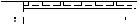
Connection diagram – MCX or MCX06
CANH-R connection should be done only on the •rst and last element of the network
Figure 1: MCX06D / AK-PC 551


 *
*
<![endif]>G
<![if ! IE]><![endif]>R H L N
<![if ! IE]><![endif]>D
G
R H L N 


D
POWER
SUPPLY
24 V AC
CAN
POWER SUPPLY 24 V AC 12 V DC
MMIGRS2
<![endif]>G R H L N D
MCX06D / AK-PC551
© Danfoss | Climate Solutions | 2021.03 |
AI184386420971en-000601 | 2 |
 Loading...