


 Loading...
Operating Guide
VACON® NXP Advanced Safety Options
OPTBL, OPTBM, OPTBN
drives.danfoss.com 


VACON® NXP Advanced Safety Options |
|
Operating Guide |
Contents |
Contents
1 Introduction |
9 |
|
1.1 |
Purpose of the Manual |
9 |
1.2 |
Additional Resources |
9 |
1.3 |
Manual and Software Version |
10 |
1.4 |
Approvals and Certificates |
12 |
1.5 |
Product Overview |
15 |
1.6 |
Terms and Abbreviations |
16 |
2 Safety |
19 |
|
2.1 |
Safety Symbols |
19 |
2.2 |
Danger and Warnings |
19 |
2.3 |
Cautions and Notices |
20 |
2.4 |
Grounding |
22 |
3 Overview of the System |
24 |
||
3.1 |
Using the Advanced Safety Options |
24 |
|
3.2 |
The Safe State |
24 |
|
3.3 |
Integration and Interfaces to Other Systems |
25 |
|
3.4 |
Determining the Achieved Safety Level |
25 |
|
3.5 |
Advanced Safety Option Variants |
27 |
|
|
3.5.1 |
General Information |
27 |
|
3.5.2 |
Input Configuration |
27 |
|
3.5.3 |
Output Configuration |
28 |
|
3.5.4 |
Option Board OPTBL |
30 |
|
3.5.5 |
Option Board OPTBM |
31 |
|
3.5.6 |
Option Board OPTBN |
32 |
|
3.5.7 Closed-loop Control with OPTBM |
33 |
|
|
3.5.8 Closed-loop Control with OPTBN |
33 |
|
3.6 |
Speed Measurement |
33 |
|
|
3.6.1 |
Safety Speed Sensors |
33 |
|
3.6.2 Standard Speed Sensors and Combinations |
33 |
|
|
3.6.3 Speed Discrepancy with Multiple Speed Sources |
35 |
|
|
3.6.4 |
Encoders |
35 |
|
3.6.5 |
Proximity sensors |
38 |
|
3.6.6 |
Encoder Signal Verification |
39 |
|
3.6.7 Usage of Only One Speed Sensor |
39 |
|
|
3.6.8 |
Estimated Speed |
40 |
|
|
||
Danfoss A/S © 2021.06 |
AQ319736045637en-000101/DPD01798 | 3 |
||

VACON® NXP Advanced Safety Options |
|
|||
Operating Guide |
Contents |
|||
|
|
|
|
|
|
|
3.6.9 |
Estimated Speed and Gear Systems |
42 |
|
|
3.6.10 |
Estimated Speed and External Accelerative Forces |
43 |
|
3.7 |
Storage of Parameters |
43 |
|
|
|
3.7.1 |
Storing a Parameter File Backup |
44 |
|
|
3.7.2 |
Restoring a Parameter File from Backup |
44 |
|
3.8 |
Advanced Safety Options with the NXP Drive |
44 |
|
|
|
3.8.1 |
Requirements |
44 |
|
|
3.8.2 |
Compatibility with Drive Applications |
45 |
|
|
3.8.3 |
Option Board Menu on the Control Panel |
45 |
|
|
3.8.4 |
Fault Types |
49 |
4 |
Installation |
51 |
||
|
4.1 |
Installation Safety |
51 |
|
|
4.2 |
Installing the Option Board |
51 |
|
5 |
VACON Safe Tool |
53 |
||
|
5.1 |
Functions of the VACON Safe Tool |
53 |
|
|
5.2 |
The Parameter File |
53 |
|
|
5.3 |
User Levels and Password Management |
53 |
|
|
5.4 |
Setting the Parameters |
54 |
|
|
5.5 |
Saving a Verified Parameter File to the Option Board |
56 |
|
|
5.6 |
Online Monitoring |
56 |
|
|
|
5.6.1 |
Viewing the State of the Option Board |
56 |
|
|
5.6.2 |
Activity Log |
56 |
6 |
Safety Functions |
57 |
||
|
6.1 |
General Information |
57 |
|
|
|
6.1.1 |
The Different Safety Functions |
57 |
|
|
6.1.2 |
Safety Function States |
57 |
|
|
6.1.3 |
Activation of a Safety Function |
58 |
|
|
6.1.4 |
Violation of a Safety Function |
58 |
|
|
6.1.5 |
Acknowledgment of a Safety Function |
59 |
|
|
|
6.1.5.1 Acknowledgment of a Safety Function |
59 |
|
|
|
6.1.5.2 Start-up Acknowledgment |
63 |
|
|
6.1.6 |
Reset of a Safety Function |
63 |
|
|
6.1.7 |
Ramps |
64 |
|
6.2 |
Safe Stopping Functions |
66 |
|
|
|
6.2.1 |
Introduction to the Safe Stopping Functions |
66 |
|
|
6.2.2 |
STO - Safe Torque Off and SBC - Safe Brake Control |
67 |
|
|
|||
4 | Danfoss A/S © 2021.06 |
AQ319736045637en-000101/DPD01798 |
|||

VACON® NXP Advanced Safety Options |
|
||
Operating Guide |
|
Contents |
|
|
|
|
|
|
6.2.2.1 Introduction to the STO and SBC Functions |
67 |
|
|
6.2.2.2 The STO Function Used without the SBC Function |
68 |
|
|
6.2.2.3 The STO Function Used with the SBC Function |
68 |
|
|
6.2.2.4 The STO and SBC Signals |
69 |
|
6.2.3 |
SS1 - Safe Stop 1 |
73 |
|
|
6.2.3.1 Introduction to the SS1 Function |
73 |
|
|
6.2.3.2 |
Time Monitoring |
74 |
|
6.2.3.3 |
Zero Speed Monitoring |
74 |
|
6.2.3.4 |
Ramp Monitoring |
75 |
|
6.2.3.5 |
The SS1 Signals |
75 |
6.2.4 SS2 - Safe Stop 2 and SOS - Safe Operating Stop |
78 |
||
|
6.2.4.1 Introduction to the SS2 and SOS Functions |
78 |
|
|
6.2.4.2 |
Time Monitoring |
79 |
|
6.2.4.3 |
Zero Speed Monitoring |
79 |
|
6.2.4.4 |
Ramp Monitoring |
80 |
|
6.2.4.5 The SOS Safety Function |
80 |
|
|
6.2.4.6 The SS2 and SOS Signals |
80 |
|
6.2.5 |
SQS - Safe Quick Stop |
84 |
|
|
6.2.5.1 Introduction to the SQS Function |
84 |
|
|
6.2.5.2 |
The SQS Modes |
85 |
|
6.2.5.3 |
The SQS Signals |
85 |
6.3 Safe Monitoring Functions |
89 |
||
6.3.1 Introduction to the Safe Monitoring Functions |
89 |
||
6.3.2 |
SLS - Safe Limited Speed |
90 |
|
|
6.3.2.1 Introduction to the SLS Function |
90 |
|
|
6.3.2.2 |
Time Monitoring |
90 |
|
6.3.2.3 |
Ramp Monitoring |
91 |
|
6.3.2.4 The Speed Limit Selection of the SLS Function |
91 |
|
|
6.3.2.5 |
The SLS Signals |
92 |
6.3.3 SMS - Safe Maximum Speed |
96 |
||
|
6.3.3.1 Introduction to the SMS Function |
96 |
|
|
6.3.3.2 The Maximum Speed Monitoring |
96 |
|
|
6.3.3.3 |
The SMS Signals |
97 |
6.3.4 |
SSR - Safe Speed Range |
99 |
|
|
6.3.4.1 Introduction to the SSR Function |
99 |
|
|
6.3.4.2 |
Time Monitoring |
99 |
|
6.3.4.3 |
Ramp Monitoring |
100 |
|
6.3.4.4 |
The SSR Signals |
101 |
|
|
|
|
Danfoss A/S © 2021.06 |
|
AQ319736045637en-000101/DPD01798 | 5 |
|

VACON® NXP Advanced Safety Options |
|
||||
Operating Guide |
|
Contents |
|||
|
|
|
|
|
|
|
|
6.3.5 |
SSM - Safe Speed Monitor |
103 |
|
|
|
|
6.3.5.1 |
Introduction to the SSM Function |
103 |
|
|
|
6.3.5.2 |
Speed Monitoring |
104 |
|
|
|
6.3.5.3 |
The SSM Safe Output |
104 |
|
|
|
6.3.5.4 |
The SSM Signals |
105 |
|
6.4 Combinations of Safety Functions |
109 |
|||
7 |
Safe Fieldbuses |
|
111 |
||
|
7.1 |
PROFIsafe |
|
111 |
|
|
|
7.1.1 |
Introduction to PROFIsafe |
111 |
|
|
|
7.1.2 The Requirements and Restrictions |
111 |
||
|
|
7.1.3 Overview of the PROFIsafe System |
112 |
||
|
|
7.1.4 |
The PROFIsafe Frame |
112 |
|
|
|
7.1.5 |
Parameterization for PROFIsafe |
113 |
|
|
|
|
7.1.5.1 |
General Information on Parameterization |
113 |
|
|
|
7.1.5.2 |
PROFIsafe Watchdog Time |
114 |
|
|
|
7.1.5.3 |
The PROFIsafe Safety Function Response Time (SFRT) |
115 |
|
|
7.1.6 |
PROFIdrive on PROFIsafe |
115 |
|
|
|
|
7.1.6.1 |
General Information on PROFIdrive on PROFIsafe |
115 |
|
|
|
7.1.6.2 |
PROFIsafe over PROFIBUS |
116 |
|
|
|
7.1.6.3 |
PROFIsafe over PROFINET |
117 |
|
|
|
7.1.6.4 |
Data Mapping for PROFIdrive on PROFIsafe |
117 |
|
|
|
7.1.6.5 |
Safety Control Word 1 (S_STW1) |
117 |
|
|
|
7.1.6.6 |
Safety Status Word 1 (S_ZSW1) |
118 |
|
|
|
7.1.6.7 |
Safety Control Word 2 (S_STW2) |
119 |
|
|
|
7.1.6.8 |
Safety Status Word 2 (S_ZSW2) |
120 |
|
|
|
7.1.6.9 |
VACON Safety Control Word (VS_CW) |
122 |
|
|
|
7.1.6.10 |
VACON Safety Status Word (VS_SW) |
123 |
8 |
Parameter List |
|
125 |
||
|
8.1 |
General Parameters |
125 |
||
|
|
8.1.1 |
Parameter File Parameters |
125 |
|
|
|
8.1.2 Common Safety Function Parameters |
125 |
||
|
|
8.1.3 |
Speed Measurement Parameters |
125 |
|
|
|
8.1.4 |
Ramp Parameters |
126 |
|
|
|
8.1.5 |
Estimated Speed Parameters |
127 |
|
|
8.2 |
Safe I/O Parameters |
127 |
||
|
|
8.2.1 |
Digital Input/Output Parameters |
127 |
|
|
8.3 |
Safe Fieldbus Parameters |
129 |
||
|
|
|
|||
6 | Danfoss A/S © 2021.06 |
|
AQ319736045637en-000101/DPD01798 |
|||

VACON® NXP Advanced Safety Options |
|
||
Operating Guide |
Contents |
||
|
|
|
|
|
8.3.1 |
PROFIsafe Parameters |
129 |
8.4 |
STO and SBC Parameters |
129 |
|
8.5 |
SS1 Parameters |
130 |
|
8.6 |
SS2 and SOS Parameters |
130 |
|
8.7 |
SQS Parameters |
131 |
|
8.8 |
SLS Parameters |
132 |
|
8.9 |
SMS Parameters |
132 |
|
8.10 |
SSR Parameters |
133 |
|
8.11 |
SSM Parameters |
133 |
|
8.12 |
Validation Parameters |
134 |
|
9 Commissioning and Validation |
135 |
||
9.1 |
Preparing for Commissioning |
135 |
|
|
9.1.1 |
Preparing for Commissioning |
135 |
|
9.1.2 Procedures Before the First Start-up of the System with the Option |
135 |
|
9.2 |
Doing the First Start-up After the Installation of the Option Board |
136 |
|
9.3 |
Validating the Parameter File |
137 |
|
9.4 |
Checklist before Taking the System into Use |
137 |
|
9.5 |
Bypassing Safety Features |
137 |
|
10 Operation and Maintenance |
139 |
||
10.3 |
Resetting the Password |
141 |
|
10.4 |
Factory Reset |
141 |
|
|
10.5.1 |
Updating the Firmware |
142 |
10.6 |
Replacing the Option Board |
143 |
|
10.7 |
Replacement of Other Components of the Safety System |
143 |
|
10.8 |
Disposal |
144 |
|
11 Technical Data |
145 |
||
11.1 |
Safety Data |
145 |
|
11.2 |
Safe Input/Output Data |
145 |
|
11.3 |
Speed Measurement Data |
147 |
|
11.4 |
Safe Fieldbus Data |
149 |
|
11.5 |
Environmental Data |
149 |
|
12 Fault Tracing |
150 |
||
12.1 |
Presentation of Faults on the Control Board |
150 |
|
12.2 |
Fault Codes |
151 |
|
12.3 |
OPTAF STO and ATEX Option Board Fault Information |
172 |
|
|
|
||
Danfoss A/S © 2021.06 |
AQ319736045637en-000101/DPD01798 | 7 |
||

VACON® NXP Advanced Safety Options |
|
Operating Guide |
Contents |
13 Configuration Examples |
173 |
|
13.1 |
General Information |
173 |
13.2 |
Emergency Stop Using the STO Function |
173 |
13.3 |
SS1 Used with STO(+SBC) |
174 |
13.4 |
SS1 Without a Direct Support of the Drive Application |
176 |
13.5 |
Light Curtain Control of SLS |
177 |
13.6 |
SLS without a Direct Support of the Drive Application |
180 |
13.7 |
Using an Output of the Option Board to Control the Access to an Area |
182 |
13.8 |
PROFIdrive over PROFIsafe Using the PROFIBUS or PROFINET Option Board |
185 |
13.9 |
A Proximity Sensor for Speed Measurement |
187 |
8 | Danfoss A/S © 2021.06 |
AQ319736045637en-000101/DPD01798 |

VACON® NXP Advanced Safety Options
Operating Guide |
Introduction |
|
|
1 Introduction
1.1 Purpose of the Manual
This manual describes the VACON® Advanced Safety Options (OPTBL, OPTBM, or OPTBN). The VACON® Advanced Safety Options can be used with the VACON® NXP AC drive.
The operating guide is intended for use by qualified personnel, who are familiar with the VACON® drives and functional safety. To use the product safely, read and follow the operating instructions.
1.2 Additional Resources
Resources Available for the Drive and Optional Equipment
•VACON® NX OPTAF STO Board Manual
•VACON® NX All in One Application Guide - information on working with parameters and many application examples
•VACON® OPTE3/E5 PROFIBUS DP User Guide
•VACON® NX I/O Boards User Manual
•VACON® OPTEA/OPTE9 Ethernet Board User Guide
•VACON® Ethernet Option Boards Installation Guide
•VACON® RS485 and CAN Bus Option Boards Installation Guide
•VACON® NXP Advanced Safety Options Quick Guide
•The Operating Guide of the AC drive provides the necessary information to get the drive up and running.
Supplementary publications and manuals are available from drives.danfoss.com/knowledge-center/technical-documentation/. Standards, specifications, and official recommendations
•EN IEC-62061 – Safety of machinery – Functional safety of safety-related electrical, electronic and programmable electronic control systems, 2005
•IEC 61784-3 – Industrial communication networks – Profiles – Part 3: Functional safety fieldbuses - General rules and profile definitions, 2010
•EN ISO 13849-1 – Safety of machinery – Safety-related parts of control systems – Part 1: General principles for design, 2015
•EN IEC 60204-1 – Safety of machinery – Electrical equipment of machines – Part 1: General requirements, 2006
•EN IEC 61800-5-2 – Adjustable speed electrical power drive systems – Part 5-2: Safety requirements – Functional, 2007
•IEC 61508 – Functional safety of electrical/electronic/programmable electronic safety related systems, 2010
•EN ISO 12100 – Safety of machinery -- General principles for design -- Risk assessment and risk reduction, 2010
•ISO 14121-1 – Safety of machinery -- Risk assessment -- Part 1: Principles, 2007
•Amendment – PROFIdrive on PROFIsafe Interface for functional safety; Technical Specification for PROFIBUS and PROFINET related to PROFIdrive – Profile Drive Technology V4.1, Version 3.00.4, April 2011, Order No.: 3.272
•PROFIsafe – Profile for Safety Technology on PROFIBUS DP and PROFINET IO, Version 2.4, March 2007, Order No: 3.192b
•Recommendation of Use CNB/M/11.050, rev 05; European co-ordination of Notified Bodies for Machinery, 2013
•BGIA Report 2/2008e Functional safety of machine controls – Application of EN ISO 13849 –, 2009
Software and Configurations Files
•The firmware for the Advanced Safety Option, https://www.danfoss.com/en/service-and-support/downloads/dds/fieldbus-firm- ware/.
•VACON® Safe, https://www.danfoss.com/en/service-and-support/downloads/dds/vacon-safe/.
•The GSD/GSDML file, https://www.danfoss.com/en/service-and-support/downloads/dds/fieldbus-configuration-files/.
For US and Canadian markets:
NOTE! Download the English and French product guides with applicable safety, warning and caution information from https:// www.danfoss.com/en/service-and-support/.
REMARQUE Vous pouvez télécharger les versions anglaise et française des guides produit contenant l'ensemble des informations de sécurité, avertissements et mises en garde applicables sur le site https://www.danfoss.com/en/service-and-support/.
Danfoss A/S © 2021.06 |
AQ319736045637en-000101 / DPD01798 | 9 |

VACON® NXP Advanced Safety Options
Operating Guide |
Introduction |
|
|
1.3 Manual and Software Version
This manual is regularly reviewed and updated. All suggestions for improvement are welcome. The original language of this manual is English.
Always make sure that you use the latest or correct revision of the manual when assessing the behavior of the Advanced safety option board.
Table 1: Manual and Software Version
Manual ver- |
New features |
Firmware ver- |
Hardware ver- |
sion |
|
sion |
sion |
|
|
|
|
DPD01798B |
The first published version of this manual. |
|
|
|
|
|
|
DPD01798C |
• PROFIsafe over PROFINET information added. Chapter Safe fieldbuses |
|
|
|
|
|
|
|
and throughout the manual. |
|
|
|
• Version history table added. |
|
|
|
• Table linking option board names to option board codes. Chapter 3.5.1 |
|
|
|
General Information. |
|
|
|
• Images edited. Chapters VACON Advanced Safety Option variants and |
|
|
|
Configuration examples. |
|
|
|
• Warning added. Chapter 6.1.4 Violation of a Safety Function. |
|
|
|
• Fault settings table added. Chapter 3.8.3 Option Board Menu on the |
|
|
|
Control Panel. |
|
|
|
• Safety bypass procedure updated. Chapter 9.5 Bypassing Safety Fea- |
|
|
|
tures. |
|
|
|
• Fault codes edited. Chapter Fault codes. |
|
|
|
• New configuration example on SLS without drive application support |
|
|
|
added. Chapter 13.6 SLS without a Direct Support of the Drive Applica- |
|
|
|
tion. |
|
|
|
• Configuration examples numbered. Chapter Configuration examples. |
|
|
|
• Other minor updates. Throughout the manual. |
|
|
|
|
|
|
DPD01798D |
• Safety function acknowledgment and reset descriptions updated to |
FW0281V001 |
70CVB01938 F |
|
or later |
(141X4588) or |
|
|
match new behavior. Chapters 6.1.5.1 Acknowledgment of a Safety |
||
|
|
later, |
|
|
Function and 6.1.6 Reset of a Safety Function. |
|
|
|
|
70CVB01957 F |
|
|
• Example of system level calculations updated. Chapter 3.4 Determining |
|
|
|
|
(141X4608) or |
|
|
the Achieved Safety Level. |
|
later, |
|
• Encoder terminals updated. Chapters 3.5.5 Option Board OPTBM and |
|
70CVB01958 E |
|
3.5.6 Option Board OPTBN. |
|
(141X4610) or |
|
• Option board installation instructions updated. Chapter 4.2 Installing |
|
later |
|
|
|
|
|
the Option Board. |
|
|
|
• Extended slot support and example configuration updated. Chapter 3.1 |
|
|
|
Using the Advanced Safety Options. |
|
|
|
• Comment on closed-loop control added. Chapter 3.6.7 Usage of Only |
|
|
|
One Speed Sensor. |
|
|
|
• Old parameters edited and new added. Chapter 3.8.3 Option Board |
|
|
|
Menu on the Control Panel. |
|
|
|
• Watchdog times updated. Chapter 7.1.5.2 PROFIsafe Watchdog Time. |
|
|
|
• Technical details updated. Chapter 11.1 Safety Data. |
|
|
|
• Fault codes updated. Chapter Fault codes. |
|
|
|
• Images edited. Chapters 3.1 Using the Advanced Safety Options, 3.6.8 |
|
|
|
Estimated Speed, 6.2.3.5 The SS1 Signals, 6.3.4.2 Time Monitoring, |
|
|
|
6.3.4.3 Ramp Monitoring, 13.3 SS1 Used with STO(+SBC), 13.5 Light Cur- |
|
|
|
|
||
10 | Danfoss A/S © 2021.06 |
AQ319736045637en-000101 / DPD01798 |
||
VACON® NXP Advanced Safety Options |
|
|
|
Operating Guide |
|
Introduction |
|
|
|
|
|
|
|
|
|
Manual ver- |
New features |
Firmware ver- |
Hardware ver- |
sion |
|
sion |
sion |
|
|
|
|
|
tain Control of SLS, and 13.6 SLS without a Direct Support of the Drive |
|
|
|
Application. |
|
|
|
• Other minor updates. Throughout the manual. |
|
|
|
|
|
|
DPD01798E |
• New chapter added, 3.6.3 Speed Discrepancy with Multiple Speed Sour- |
FW0281V001 |
70CVB01938 F |
|
or later |
(141X4588) or |
|
|
ces. |
||
|
|
later, |
|
|
• Information on internal variables added. Chapter 10.1 Gathering Diag- |
|
|
|
|
70CVB01957 F |
|
|
nostic Data. |
|
(141X4608) or |
|
• Some fault numbers for fault code 20 Safety system updated. Chapter |
|
later, |
|
Fault codes. |
|
70CVB01958 E |
|
• OPTAF option board fault information added. Chapter 12.3 OPTAF STO |
|
(141X4610) or |
|
|
later |
|
|
and ATEX Option Board Fault Information. |
|
|
|
|
|
|
|
• Other minor updates. Throughout the manual. |
|
|
|
|
|
|
DPD01798F |
• PROFINET IO/PROFIsafe Certificate updated. 1.4 Approvals and Certifi- |
FW0281V001 |
70CVB01938 F |
|
or later |
(141X4588) or |
|
|
cates. |
||
|
|
later, |
|
|
• Changes in layout and structure. |
|
|
|
|
70CVB01957 F |
|
|
|
|
(141X4608) or |
|
|
|
later, |
|
|
|
70CVB01958 E |
|
|
|
(141X4610) or |
|
|
|
later |
|
|
|
|
Danfoss A/S © 2021.06 |
AQ319736045637en-000101 / DPD01798 | 11 |

VACON® NXP Advanced Safety Options |
|
Operating Guide |
Introduction |
1.4 Approvals and Certificates
<![if ! IE]><![endif]>e30bi948.10
Illustration 1: TÜV Certificate
12 | Danfoss A/S © 2021.06 |
AQ319736045637en-000101 / DPD01798 |

VACON® NXP Advanced Safety Options |
|
Operating Guide |
Introduction |
|
|
|
<![if ! IE]> <![endif]>e30bi950.10 |
Certificate
PROFIBUS Nutzerorganisation e.V. grants to
Vacon Ltd
Runsorintie 7, 65380 VAASA, FINLAND
the Certificate No: Z20212 for the PROFIsafe Device:
Model Name: |
Vacon OPTEA, OPTBL, OPTBM, OPTBN Advanced Safety Option |
Order-Number: |
OPTBL, OPTBM, OPTBN |
Revision: |
SW/FW: V4.0.0; HW: 6 |
Application CRC: Channel A: 0x84C3
Channel B: 0xCB77
This certificate confi rms that the product has successfully passed the certifi cation tests with the following PROFIsafe scope:

 PROFIsafe_V2 functionality on PROFINET IO
Test Report Number: |
PS127-2 |
Authorized Test Laboratory: |
SIEMENS AG, Fürth, Germany |
The tests were executed in accordance with the following documents:
“PROFIsafe - Test Specification for F-Slaves, F-Devices, and F-Hosts, Version 2.1, March 2007”.
This certificate is granted according to the document:
“Framework for testing and certification of PROFIBUS and PROFINET products”.
For all products that are placed in circulation by March 19, 2023 the certificate is valid for life.
Karlsruhe, May 14, 2020 |
Board of PROFIBUS Nutzerorganisation e. V. |
_____________________________ |
|
(Official in Charge) |
_____________________________ |
|
(Karsten Schneider) |
|
_____________________________ |
|
(Dr. Jörg Hähniche) |
Illustration 2: PROFINET IO/PROFIsafe Certificate
Danfoss A/S © 2021.06 |
AQ319736045637en-000101 / DPD01798 | 13 |

VACON® NXP Advanced Safety Options |
|
Operating Guide |
Introduction |
|
|
|
<![if ! IE]> <![endif]>e30bi949.10 |
Illustration 3: EC Declaration of Conformity
14 | Danfoss A/S © 2021.06 |
AQ319736045637en-000101 / DPD01798 |

VACON® NXP Advanced Safety Options
Operating Guide |
Introduction |
|
|
1.5 Product Overview
The Advanced safety option board is intended to be used for implementing safety functions according to application needs. The option board is intended to be used with the OPTAF STO option board to implement the safety functions and features in VACON® NX drives.
The safety functions available with the Advanced safety option board (according to EN IEC 61800-5-2)
•Safe Torque Off (STO)
•Safe Stop 1 (SS1)
•Safe Stop 2 (SS2)
•Safe Operating Stop (SOS)
•Safe Brake Control (SBC)
•Safe Limited Speed (SLS)
•Safe Speed Range (SSR)
•Safe Speed Monitor (SSM)
The manufacturer-specific safety functions
•Safe Maximum Speed (SMS)
•Safe Quick Stop (SQS)
For more information on the safety functions, see chapter Safety functions.
The safe fieldbuses supported by the option board
•PROFIsafe communication over PROFIBUS
•PROFIsafe communication over PROFINET
Communication over PROFIsafe is implemented according to the PROFIdrive on PROFIsafe amendment.
 W A R N I N G
DESIGNING OF SAFETY SYSTEMS
Designing a safety-related system incorrectly could result in death or serious injury.
-The designing of safety-related systems requires special knowledge and skills.
-Only qualified persons are permitted to install and set up the product.
 W A R N I N G
RISK ASSESSMENT OF A SAFETY SYSTEM
The use of safety functions provided by the Advanced Safety Option does not in itself ensure safety.
-To make sure that the commissioned system is safe, you must make an overall risk assessment.
-Safety devices like the Advanced safety option board must be correctly incorporated into the entire system.
-The entire system must be designed in compliance with all relevant standards within the field of industry. Standards such as EN 12100 Part 1, Part 2, and ISO 14121-1 provide methods for designing safe machinery and for making a risk assessment.
 C A U T I O N
PROTECTION AGAINST CONTAMINATION
For the product to work properly, it must be protected against conductive dust and contaminants.
-For example, install the Advanced Safety Option board in at least an IP54 enclosure.
N O T I C E
This guide provides information on the use of the safety functions that the Advanced Safety Option provides. This information is in compliance with accepted practice and regulations at the time of writing. However, the product/system designer is responsible for making sure that the system is safe and in compliance with relevant regulations.
Danfoss A/S © 2021.06 |
AQ319736045637en-000101 / DPD01798 | 15 |

VACON® NXP Advanced Safety Options
Operating Guide Introduction
1.6 Terms and Abbreviations
Table 2: Symbols and Abbreviations
Abbreviation |
Definition |
|
|
Admin |
The highest user level for accessing the Advanced safety option board functions. Identified via a pass- |
|
word. |
|
|
Acknowledgment |
A signal that indicates that a safety function can be deactivated. Valid for safety functions that use man- |
|
ual acknowledgment. |
|
|
ASM |
An asynchronous motor |
|
|
Continuous mode |
Safety function is active as a part of normal operation. |
|
|
CRC |
Cyclic Redundancy Check |
|
|
CW |
Control word |
|
|
DAT |
Device Acknowledgment Time |
|
|
Diagnostic Coverage |
The coverage of dangerous failures by run-time diagnostics. |
(DC) |
|
|
|
EMC |
Electromagnetic compatibility |
|
|
Encoder interface |
An option board that has an encoder interface. |
board |
|
|
|
F-Device |
A communication peer that can perform the PROFIsafe protocol. |
|
|
F-Host |
A data processing unit that can perform the PROFIsafe protocol and service the "black channel". |
|
|
FMEA |
Failure Mode and Effects Analysis |
|
|
Critical fault |
A fault that causes the option board to enter into a fault state and requires a reboot to be reset. |
|
|
GSD |
Generic Station Description (used with PROFIBUS). |
|
|
GSDML |
General Station Description Markup Language (used with PROFINET). |
|
|
Hardware Fault Tol- |
The number of hardware failures that the safety system can tolerate without the loss of the safety func- |
erance (HFT) |
tion. |
|
|
HAT |
Host Acknowledgment Time. |
|
|
High demand mode |
Safety functions are performed on demand. The frequency of demand is more than once a year. |
|
|
HTL |
High Threshold Logic. A voltage level definition. |
|
|
I/O |
Input/Output |
|
|
Low demand mode |
Safety functions are performed on demand. The frequency of demand is less than once a year. |
|
|
MTTF |
Mean Time To Failure |
|
|
OPTAF |
An option board that handles the activation of the STO function for the AC drive. |
|
|
OPTBL, OPTBM, |
The variants of the Advanced safety option. OPTBL: no encoder interface. OPTBM: with digital pulse type |
OPTBN |
encoder interface board. OPTBN: with Sin/Cos type encoder interface board. |
|
|
OPTE3/5 |
Option board that handles the PROFIBUS DP interface. |
|
|
OPTEA |
Option board that handles the PROFINET IO interface. |
|
|
|
|
16 | Danfoss A/S © 2021.06 |
AQ319736045637en-000101 / DPD01798 |

VACON® NXP Advanced Safety Options
Operating Guide |
Introduction |
|
|
|
|
Abbreviation |
Definition |
|
|
Parameter file |
A configuration file that contains the parameters for an Advanced safety option board. |
|
|
Unverified parame- |
A parameter file that contains parameters that have not been verified by an Advanced safety option |
ter file |
board. |
|
|
Verified parameter |
A parameter file that contains parameters that have been verified and can be used in an Advanced safety |
file |
option board. |
|
|
Validated parameter |
A verified parameter file that contains parameters that have been tested and approved in the system. |
file |
|
|
|
PFH |
Probability of failure per hour. Valid for systems that operate in a high demand mode or continuous |
|
mode. |
|
|
PFHd |
Probability of dangerous failure per hour. |
|
|
PFD |
Probability of failure on demand. The probability that the safety function does not work when requested. |
|
Valid for systems that operate in a low demand mode. |
|
|
PL |
Performance Level |
|
|
PLC |
Programmable Logic Controller |
|
|
PMSM |
A permanent magnet synchronous motor |
|
|
PROFIBUS |
Standardized fieldbus protocol for RS-485 communication. |
|
|
PROFIdrive |
A specification for implementing AC drive related behavior over PROFIBUS/ PROFINET. |
|
|
PROFINET |
Standardized fieldbus protocol for Ethernet communication. |
|
|
PROFIsafe |
A safe fieldbus layer that operates over PROFIBUS/PROFINET. |
|
|
Reached |
A safety function that is reached has stopped the drive (safe stopping functions), or reached a safe area |
|
for the measured value and monitoring for leaving the area has been activated (safe monitoring func- |
|
tions). |
|
|
Resettable fault |
An error in that can be reset with a reset signal. |
|
|
Reset (signal) |
A signal used to reset the current violations and faults in the drive and/or the Advanced safety option |
|
board and to deactivate the STO function after a violation or fault. |
|
|
SFF |
Safe Failure Fraction |
|
|
Safe monitoring |
A safety function that monitors a specific value, usually speed. |
function |
|
|
|
Safe stopping func- |
A safety function intended to stop the motor. |
tion |
|
|
|
Safe range |
A range where the monitored value can be. Exceeding the limits of a safe range will cause a violation of |
|
the safety function. |
|
|
Safe state |
A state of a device or process that should be maintained to avoid dangerous incidents. For the AC drive |
|
system, the safe state is defined as activated STO function. |
|
|
Service |
A user level for accessing the Advanced safety option board functions. Identified via a password. In this |
|
user level, it is not possible to verify a parameter file or change passwords. |
|
|
SFRT |
Safety Function Response Time |
|
|
SRP/CS |
Safety-Related Part of a Control System |
|
|
|
|
Danfoss A/S © 2021.06 |
AQ319736045637en-000101 / DPD01798 | 17 |

VACON® NXP Advanced Safety Options
Operating Guide |
Introduction |
|
|
|
|
Abbreviation |
Definition |
|
|
STO |
Safe Torque Off. A safety function according to EN IEC 61800-5-2. |
|
|
SS1 |
Safe Stop 1. A safety function according to EN IEC 61800-5-2. |
|
|
SS2 |
Safe Stop 2. A safety function according to EN IEC 61800-5-2. |
|
|
SQS |
Safe Quick Stop. A manufacturer-specific safety function. Used as a violation response for safe monitoring |
|
functions. Parameterizable to behave as the STO, SS1 or SS2 function. |
|
|
SQS-STO, SQS-SS1, |
Used to indicate the STO, SS1 or SS2 function as the selected behavior of the SQS function. |
SQS-SS2 |
|
|
|
SLS |
Safe Limited Speed. A safety function according to EN IEC 61800-5-2. |
|
|
SSR |
Safe Speed Range. A safety function according to EN IEC 61800-5-2. |
|
|
SSM |
Safe Speed Monitor. A safety function according to EN IEC 61800-5-2. |
|
|
SMS |
Safe Maximum Speed. A manufacturer-specific safety function. |
|
|
SBC |
Safe Brake Control. A safety function according to EN IEC 61800-5-2. |
|
|
SOS |
Safe Operating Stop. A safety function according to EN IEC 61800-5-2. |
|
|
SIL |
Safety Integrity Level |
|
|
SW |
Status word |
|
|
TTL |
Transistor-Transistor Logic. A voltage level definition. |
|
|
Violation |
A fault caused by a safety function detecting a violation of the monitored value(s). The value monitored |
|
by a safety function has exceeded the set limit for that value. |
|
|
Violation response |
A reaction to a violation. It is the STO function for the safe stopping functions, and the SQS function for |
|
the safe monitoring functions. |
|
|
WCDT |
Worst Case Delay Time |
|
|
WDTime |
Watchdog Time |
|
|
18 | Danfoss A/S © 2021.06 |
AQ319736045637en-000101 / DPD01798 |

VACON® NXP Advanced Safety Options
Operating Guide |
Safety |
|
|
2 Safety
2.1 Safety Symbols
The following symbols are used in this manual:
 D A N G E R
Indicates a hazardous situation which, if not avoided, will result in death or serious injury.
 W A R N I N G
Indicates a hazardous situation which, if not avoided, could result in death or serious injury.
 C A U T I O N
Indicates a hazardous situation which, if not avoided, could result in minor or moderate injury.
N O T I C E
Indicates information considered important, but not hazard-related (for example, messages relating to property damage).
2.2 Danger and Warnings
 D A N G E R
SHOCK HAZARD FROM POWER UNIT COMPONENTS
The power unit components are live when the drive is connected to mains. A contact with this voltage can lead to death or serious injury.
-Do not touch the components of the power unit when the drive is connected to mains. Before connecting the drive to mains, make sure that the covers of the drive are closed.
 D A N G E R
SHOCK HAZARD FROM TERMINALS
The motor terminals U, V, W, the brake resistor terminals, or the DC terminals are live when the drive is connected to mains, also when the motor does not operate. A contact with this voltage can lead to death or serious injury.
-Do not touch the motor terminals U, V, W, the brake resistor terminals, or the DC terminals when the drive is connected to mains. Before connecting the drive to mains, make sure that the covers of the drive are closed.
 D A N G E R
SHOCK HAZARD FROM DC LINK OR EXTERNAL SOURCE
The terminal connections and the components of the drive can be live 5 minutes after the drive is disconnected from the mains and the motor has stopped. Also the load side of the drive can generate voltage. A contact with this voltage can lead to death or serious injury.
-Before doing electrical work on the drive:
Disconnect the drive from the mains and make sure that the motor has stopped. Lock out and tag out the power source to the drive.
Make sure that no external source generates unintended voltage during work. Wait 5 minutes before opening the cabinet door or the cover of the AC drive. Use a measuring device to make sure that there is no voltage.
Danfoss A/S © 2021.06 |
AQ319736045637en-000101 / DPD01798 | 19 |

VACON® NXP Advanced Safety Options
Operating Guide |
Safety |
|
|
W A R N I N G 
SHOCK HAZARD FROM CONTROL TERMINALS
The control terminals can have a dangerous voltage also when the drive is disconnected from mains. A contact with this voltage can lead to injury.
-Make sure that there is no voltage in the control terminals before touching the control terminals.
 W A R N I N G
ACCIDENTAL MOTOR START
When there is a power-up, a power break, or a fault reset, the motor starts immediately if the start signal is active, unless the pulse control for Start/Stop logic is selected. If the parameters, the applications or the software change, the I/O functions (including the start inputs) can change. If you activate the auto reset function, the motor starts automatically after an automatic fault reset. See the Application Guide. Failure to ensure that the motor, system, and any attached equipment are ready for start can result in personal injury or equipment damage.
-Disconnect the motor from the drive if an accidental start can be dangerous. Make sure that the equipment is safe to operate under any condition.
 W A R N I N G
LEAKAGE CURRENT HAZARD
Leakage currents exceed 3.5 mA. Failure to ground the drive properly can result in death or serious injury.
-Ensure the correct grounding of the equipment by a certified electrical installer.
 W A R N I N G
SHOCK HAZARD FROM PE CONDUCTOR
The drive can cause a DC current in the PE conductor. Failure to use a residual current-operated protective (RCD) device Type B or a residual current-operated monitoring (RCM) device can lead to the RCD not providing the intended protection and therefore can result in death or serious injury.
-Use a type B RCD or RCM device on the mains side of the drive.
2.3 Cautions and Notices
 C A U T I O N
DAMAGE TO THE AC DRIVE FROM INCORRECT MEASUREMENTS
Doing measurements on the AC drive when it is connected to mains can damage the drive.
-Do not do measurements when the AC drive is connected to mains.
 C A U T I O N
DAMAGE TO THE AC DRIVE FROM INCORRECT SPARE PARTS
Using spare parts that are not from the manufacturer can damage the drive.
-Do not use spare parts that are not from the manufacturer.
 C A U T I O N
DAMAGE TO THE AC DRIVE FROM INSUFFICIENT GROUNDING
Not using a grounding conductor can damage the drive.
-Make sure that the AC drive is always grounded with a grounding conductor that is connected to the grounding terminal that is identified with the PE symbol.
20 | Danfoss A/S © 2021.06 |
AQ319736045637en-000101 / DPD01798 |
VACON® NXP Advanced Safety Options
Operating Guide |
Safety |
|
|
 C A U T I O N
CUT HAZARD FROM SHARP EDGES
There can be sharp edges in the AC drive that can cause cuts.
-Wear protective gloves when mounting, cabling, or doing maintenance operations.
 C A U T I O N
BURN HAZARD FROM HOT SURFACES
Touching surfaces, which are marked with the 'hot surface' sticker, can result in injury.
-Do not touch surfaces which are marked with the 'hot surface' sticker.
N O T I C E
DAMAGE TO THE AC DRIVE FROM STATIC VOLTAGE
Some of the electronic components inside the AC drive are sensitive to ESD. Static voltage can damage the components.
-Remember to use ESD protection always when working with electronic components of the AC drive. Do not touch the components on the circuit boards without proper ESD protection.
N O T I C E
DAMAGE TO THE AC DRIVE FROM MOVEMENT
Movement after installation can damage the drive.
-Do not move the AC drive during operation. Use a fixed installation to prevent damage to the drive.
N O T I C E
DAMAGE TO THE AC DRIVE FROM INCORRECT EMC LEVEL
The EMC level requirements for the AC drive depend on the installation environment. An incorrect EMC level can damage the drive.
-Before connecting the AC drive to the mains, make sure that the EMC level of the AC drive is correct for the mains.
N O T I C E
RADIO INTERFERENCE
In a residential environment, this product can cause radio interference.
-Take supplementary mitigation measures.
N O T I C E
MAINS DISCONNECTION DEVICE
If the AC drive is used as a part of a machine, the machine manufacturer must supply a mains disconnection device (refer to EN 60204-1).
N O T I C E
MALFUNCTION OF FAULT CURRENT PROTECTIVE SWITCHES
Because there are high capacitive currents in the AC drive, it is possible that the fault current protective switches do not operate correctly.
Danfoss A/S © 2021.06 |
AQ319736045637en-000101 / DPD01798 | 21 |

VACON® NXP Advanced Safety Options
Operating Guide |
Safety |
|
|
N O T I C E
VOLTAGE WITHSTAND TESTS
Doing voltage withstand tests can damage the drive.
-Do not do voltage withstand tests on the AC drive. The manufacturer has already done the tests.
2.4 Grounding
Ground the AC drive in accordance with applicable standards and directives.
 C A U T I O N
DAMAGE TO THE AC DRIVE FROM INSUFFICIENT GROUNDING
Not using a grounding conductor can damage the drive.
-Make sure that the AC drive is always grounded with a grounding conductor that is connected to the grounding terminal that is identified with the PE symbol.
 W A R N I N G
LEAKAGE CURRENT HAZARD
Leakage currents exceed 3.5 mA. Failure to ground the drive properly can result in death or serious injury.
-Ensure the correct grounding of the equipment by a certified electrical installer.
The standard EN 61800-5-1 tells that 1 or more of these conditions for the protective circuit must be true.
The connection must be fixed.
•The protective earthing conductor must have a cross-sectional area of minimum 10 mm2 Cu or 16 mm2 Al. OR
•There must be an automatic disconnection of the mains, if the protective earthing conductor breaks. OR
•There must be a terminal for a second protective earthing conductor in the same cross-sectional area as the first protective earthing conductor.
Cross-sectional area of the phase conductors (S) [mm2] |
The minimum cross-sectional area of the protective earthing con- |
|
|
|
ductor in question [mm2] |
S ≤ 16 |
S |
|
|
|
|
16 |
< S ≤ 35 |
16 |
|
|
|
35 |
< S |
S/2 |
|
|
|
The values of the table are valid only if the protective earthing conductor is made of the same metal as the phase conductors. If this is not so, the cross-sectional area of the protective earthing conductor must be determined in a manner that produces a conductance equivalent to that which results from the application of this table.
The cross-sectional area of each protective earthing conductor that is not a part of the mains cable or the cable enclosure, must be a minimum of:
•2.5 mm2 if there is mechanical protection, and
•4 mm2 if there is not mechanical protection. With cord-connected equipment, make sure that the protective earthing conductor in the cord is the last conductor to be interrupted, if the strain-relief mechanism breaks.
Obey the local regulations on the minimum size of the protective earthing conductor.
N O T I C E
MALFUNCTION OF FAULT CURRENT PROTECTIVE SWITCHES
Because there are high capacitive currents in the AC drive, it is possible that the fault current protective switches do not operate correctly.
22 | Danfoss A/S © 2021.06 |
AQ319736045637en-000101 / DPD01798 |

VACON® NXP Advanced Safety Options
Operating Guide |
Safety |
|
|
N O T I C E
VOLTAGE WITHSTAND TESTS
Doing voltage withstand tests can damage the drive.
-Do not do voltage withstand tests on the AC drive. The manufacturer has already done the tests.
 W A R N I N G
SHOCK HAZARD FROM PE CONDUCTOR
The drive can cause a DC current in the PE conductor. Failure to use a residual current-operated protective (RCD) device Type B or a residual current-operated monitoring (RCM) device can lead to the RCD not providing the intended protection and therefore can result in death or serious injury.
-Use a type B RCD or RCM device on the mains side of the drive.
Danfoss A/S © 2021.06 |
AQ319736045637en-000101 / DPD01798 | 23 |

VACON® NXP Advanced Safety Options
Operating Guide |
Overview of the System |
|
|
3 Overview of the System
3.1 Using the Advanced Safety Options
The Advanced safety option board is used to implement safety functions in accordance with the standard EN IEC 61800-5-2. The option board handles the safe I/O and the monitoring of active safety functions. The option board does not handle the control of the AC drive. The AC drive can be controlled, for example, with the drive application, or the external process control system can give the speed reference to the AC drive.
The Advanced safety option board must be used with a subsystem that provides the STO function, it is not possible to use the Advanced safety option board alone. The STO function is provided, for example, by the OPTAF STO option board. To use the safety functions that do speed monitoring, an external speed sensor is necessary. The sensor can be a digital or an analog encoder or a digital proximity sensor. See chapter Speed Measurement.
The Advanced safety option board can be used with the digital I/O and over safe fieldbus. Using a safe fieldbus allows you to control more safety functions than is possible with the limited number of inputs and outputs that the Advanced safety option board has.
When using a safe fieldbus, install an option board that supports the fieldbus. See 7.1.1 Introduction to PROFIsafe.
The Illustration 4 shows the configuration of the AC drive with the Advanced safety option board in slot C. The safe fieldbus and the closed-loop control are optional. The possible configuration and available features can depend on other option boards and their installation slots. For use cases with other encoder board installed in slot C, see 3.6.4 Encoders.
NCDrive |
|
VACON® Loader |
|
VACON® Safe |
PC
<![endif]>e30bi367.10
|
|
|
|
|
Drive |
|
|
Control Board |
|
|
|
Power |
|
|
|
|
|
Unit |
|
|
|
|
|
|
SLOT A |
SLOT B |
SLOT C |
SLOT D |
SLOT E |
|
Basic I/O |
STO |
Advanced |
|
Fieldbus |
|
safety |
|
|||
|
|
option |
option |
|
board |
|
|
board |
board |
|
|
|
|
STO |
Digital |
Safe |
|
|
|
Encoder |
I/O |
|
fieldbus |
Motor |
Encoder |
|
|
|
|
signals |
|
|
|
||
|
|
|
|
|
|
|
|
|
Safety PLC or other safety systems |
||
Illustration 4: An example configuration of the VACON® NXP drive with the Advanced safety option board. The subsystems that handle safety actions are marked in gray.
The parameterization of the option board is done by selecting and editing the safety functions and features with the VACON® Safe tool. See 5.4 Setting the Parameters and chapter Parameter List.
3.2 The Safe State
There must be a safe state to which the system can be set when necessary. Usually the safe state is reached when the AC drive does not generate torque to the motor shaft. In the Advanced safety option board, this is realized by the Safe Torque Off (STO) safety function.
In some systems, the active STO function in the AC drive does not create a safe state. It means that external forces can generate torque to the motor shaft and cause it to rotate. To achieve the safe state in these systems, additional means are necessary. For example, it is possible to use the STO function and a mechanical brake. The brake can be used with the Safe Brake Control (SBC) safety function of the Advanced option board, or with another safe control system for the brake.
24 | Danfoss A/S © 2021.06 |
AQ319736045637en-000101 / DPD01798 |

VACON® NXP Advanced Safety Options
Operating Guide |
Overview of the System |
|
|
The Advanced safety option board forces the AC drive to the safe state, for example, if there is an error detected in the safety system. Other situations when the safe state is enforced are, for example, the parameterization phase and during the start-up of the drive.
3.3 Integration and Interfaces to Other Systems
When the Advanced safety option board is integrated to a safety system, the system designer and/or the operator is responsible for these things:
•Making an initial system-level risk assessment and reassessing the system any time a change is made.
•The setup and suitability of parameters, sensors, and actuators used in the system.
•Validation of the system to the correct safety level.
•Maintenance and periodic testing.
•Controlling the access to the system, including password handling.
External systems can collect information from the Advanced safety option board in a few different ways.
The option board related fault and violation information is available in the fault log of the AC drive like other faults. This data must be interpreted differently to the fault data of the AC drive. See chapter Fault tracing.
The option board has configurable outputs where desired information can be set to be sent to external systems. The status data can be received over a safe fieldbus.
3.4 Determining the Achieved Safety Level
 W A R N I N G
SAFETY AWARENESS IN DESIGN
This chapter is an example and contains simplifications. Using only this data in designing the system can damage the equipment.
-
-
Do not use this chapter as a template for designing your system. Perform the design work carefully.
The achieved safety level depends on the whole safety chain. The AC drive with integrated safety functions is only one component in the safety chain.
The things related to the AC drive that affect the achieved safety level:
•The used speed measurement combination.
•The implementation of the violation response and of the fault response. In most cases it is realized via the STO option board (the OPTAF option board for the VACON® NX products).
The components of the safety chain that affect the achieved safety level:
•The controllers (for example, the safety PLC) that control the safety functions
•The stop switches
•The wiring
EXAMPLE
Implementation of the STO safety function, consisting of these subsystems.
•Emergency stop switch: Pilz PIT es Set/1-family using two N/C contacts. B10d = 104 000 (EN ISO 13849-1) and λd/ λ = 0.20 (EN IEC 62061) for one channel.
•The OPTAF option board, version VB00328H (141L7786). A two-channel STO option board for the NX family.
•The Advanced safety option board OPTBL.
N O T I C E
Check the corresponding product guides for the safety values and usage instructions.
Danfoss A/S © 2021.06 |
AQ319736045637en-000101 / DPD01798 | 25 |

VACON® NXP Advanced Safety Options
Operating Guide |
Overview of the System |
|
|
|
(SIL3, |
Cat 4) |
(SIL3, PLe, |
<![if ! IE]> <![endif]>e30bi368.10 |
|
Emergency |
OPTBL |
OPTAF & |
|
|
stop switch |
(SIL3, PLe, |
AC drive |
|
|
PLe) |
|
Cat 3) |
|
Channel 1 |
Stop (STO) request |
|
STO |
|
Channel 2 |
Stop (STO) request |
|
STO |
|
Illustration 5: A Logical Presentation of the STO Safety Function |
|
|
|
|
In this example case, the STO function has one activation per day, and a lifetime of 20 years. For the emergency stop switch, β = 10% is used as the susceptibility to common cause failure between the channels. No proof test is executed during the lifetime. The example system is limited to Category 3 because the Category 3 element OPTAF option board is used as a single final element.
Table 3: An Example of System Level Calculations for the STO Safety Function
Subsystem |
SIL, PL |
PFHd |
PFDavg |
DCavg [%] |
MTTFd [a] |
|
Emergency stop switch |
SIL3, PLe |
4.2 x 10⁻⁹(1) |
3.7 x 10⁻⁴(2) |
90(3) |
2849.3 (4)(4) |
|
OPTBL |
SIL3, PLe |
6.45 x 10⁻¹¹ |
5.61 x 10⁻⁶ |
99 |
373 |
|
|
|
|
|
|
|
|
OPTAF |
SIL3, PLe |
2.7 x 10⁻⁹ |
1.3 x 10⁻⁴ |
60(5) |
1918 |
|
Overall safety system (for STO) |
SIL3, PLe |
6.94 x 10⁻⁹(6) |
5.06 x 10⁻⁴(7) |
74(8) |
281(9) |
|
|
|
|
|
|
|
|
1This value is calculated directly from the values provided by the manufacturer. The diagnostic capabilities of OPTBL have not been taken into account. The calculation formula: PFHd = (1- β)2 x λch1 x λch2 x T1 + β x (λch1 + λch2)/2, where λch = (0.1 x cycles per hour) / B10d).
2The calculation formula: PFDavg = (PFHd x TM)/2.
3The OPTBL executes "Cross monitoring of inputs without dynamic test", DC: 0%...99%, depending on how often a signal change is done by the application. A DC of 90% is assumed with the once a day activation.
4The calculation formula: MTTFd = B10d / (0.1 x cycles per year).
5OPTAF manual: DCavg = low, using the lower end of the possible range (60%...90%)
6Sum of the individual PFHd values.
7Sum of the individual PFHavg values.
8The calculation formula:
|
DCSwitch |
+ |
DCOPTBL |
+ |
DCOPTAF |
|
DCavg STO = |
MTTFd Switch |
MTTFd OPTBL |
MTTFd OPTAF |
|
||
1 |
+ |
1 |
+ |
1 |
|
|
|
|
|||||
|
MTTFd Switch |
MTTFd OPTBL |
MTTFd OPTAF |
|
||
9 According to EN ISO 13849-1, the MTTFd must be limited to a maximum limit of 100 years per channel. The calculation formula:
MTTFd STO = |
|
|
1 |
|
|
|
1 |
+ |
1 |
+ |
1 |
|
|
|
|
|||||
|
MTTFd Switch |
MTTFd OPTBL |
MTTFd OPTAF |
|
N O T I C E
When designing systems according to IEC-61508, the requirement for the value of the Safe Failure Fraction (SFF) is considered on subsystem level, not on system level.
26 | Danfoss A/S © 2021.06 |
AQ319736045637en-000101 / DPD01798 |

VACON® NXP Advanced Safety Options
Operating Guide |
Overview of the System |
|
|
3.5 Advanced Safety Option Variants
3.5.1 General Information
Newer versions of the Advanced Safety Option have extended slot compatibility. The table Table 4 describes the supported slots for different revisions of the option board. The compatibility is determined by the revision of the board 70CVB01938 (141X4588). See Illustration 6 for the location of the revision information.
Table 4: Supported Slots of the Revisions of the Option Board
Option board revision (70CVB01938, 141X4588) |
|
|
|
Slot C |
Slot D |
Slot E |
|
|
|
|
|
|
|
C, E |
|
|
|
- |
Yes |
- |
|
|
|
|
|
|
|
F |
|
|
|
Yes |
Yes |
Yes |
|
|
|
|
|
|
|
|
|
|
<![if ! IE]> <![endif]>e30bi413.10 |
|
|
|
|
|
|
|
|
||
|
|
|
|
|
||
|
|
|
|
|
|
|
|
|
|
|
|
|
|
|
|
|
|
|
|
|
|
|
|
|
|
|
|
|
|
|
|
|
|
|
|
|
|
|
|
|
|
|
|
|
|
|
|
|
|
|
|
|
|
|
|
Illustration 6: The Board Identification Sticker on the Advanced Safety Option Board
The Advanced safety option board contains a safe digital I/O for the control and status word signals.
The available connectors of the Advanced safety option board
•4 two-terminal digital inputs
•2 two-terminal digital outputs
•2 STO outputs
•+24 V supply
•GND
It is possible to use the digital inputs for selecting ramps and for activating, acknowledging, and resetting safety functions. The twoterminal digital outputs can be used as output signals of the SBC or the SSM function, or configured by combining various signals of the option board.
If a connected device is powered by an external power supply, make sure that there is common ground between the device and the Advanced safety option board.
N O T I C E
The digital outputs use internal diagnostic test pulses to make sure that the output logic operates correctly. These test pulses are visible to external systems. See 11.2 Safe Input/Output Data.
3.5.2 Input Configuration
The 4 two-terminal digital inputs operate in a two-terminal equivalent mode: the state of both terminals must match each other within a discrepancy time (see 11.2 Safe Input/Output Data).
Danfoss A/S © 2021.06 |
AQ319736045637en-000101 / DPD01798 | 27 |

VACON® NXP Advanced Safety Options
Operating Guide |
|
Overview of the System |
|
|
|
Table 5: The Input States |
|
|
|
|
|
Input terminal A |
Input terminal B |
State |
|
|
|
Active |
Active |
The assigned safety function is not requested. |
|
|
|
Active |
Inactive |
The assigned safety state is requested. If longer than 500 ms: the option board detects a |
|
|
fault. |
|
|
|
Inactive |
Active |
The assigned safety state is requested. If longer than 500 ms: the option board detects a |
|
|
fault. |
|
|
|
Inactive |
Inactive |
The assigned safety function is requested. |
|
|
|
It is possible to assign these tasks to each of the digital inputs:
•the request of a safety function
•the acknowledgment signal
•the reset signal
•the proximity sensor
It is possible to assign 1 task per digital input. The exceptions are the acknowledgment signal and the reset signal which can be assigned to the same input.
N O T I C E
If proximity sensors are used, it is not possible to assign safety function features to the corresponding inputs. See 3.6.5 Proximity sensors.
3.5.3 Output Configuration
The 2 two-terminal digital outputs operate in a two-terminal equivalent mode: the state of both terminals must match each other within a discrepancy time (see 11.2 Safe Input/Output Data). The external system or systems should make sure that the two terminals are in the same state.
The tasks that can be assigned to each of the digital outputs:
•the SSM function output
•the SBC function output
•simple custom logic
For more information on the SSM and the SBC function outputs, see 6.2.2.3 The STO Function Used with the SBC Function and 6.3.5.3 The SSM Safe Output.
To configure the simple custom logic for an output, select a logical function and desired signals from a configuration group. The option board uses the selected signals and applies the selected logical function to determine the state of the output.
1.Select the group that contains the desired signal or signals.
2.Select the logical function to combine the selected signals.
3.Select the signal or signals.
If only 1 signal is selected: AND or OR (regardless of which): output = signal. NAND or NOR (regardless of which): output = negative signal.
See the examples below for signal and output correspondence.
The available logical functions:
•AND
•OR
•NAND
•NOR
Only 1 logical function per output can be selected.
28 | Danfoss A/S © 2021.06 |
AQ319736045637en-000101 / DPD01798 |

VACON® NXP Advanced Safety Options |
|
|
|
Operating Guide |
|
|
Overview of the System |
|
|
|
|
Table 6: The Available Signals in Configuration Groups |
|
|
|
|
|
|
|
Group 1 and Group 5 |
Group 2 and Group 6 |
Group 3 and Group 7 |
Group 4 and Group 8 |
|
|
|
|
STO Reached |
SLS 1 Reached |
STO Active |
Warning in any safety function |
SS1 Reached |
SLS 2 Reached |
SS1 Active |
Limit violation fault in any safety function |
SS2 Reached |
SLS 3 Reached |
SS2 Active |
|
SQS Reached |
SSR Reached |
SQS Active |
|
SOS Reached |
SMS Reached |
SLS 1 Active |
|
SBC Reached |
SSM Reached |
SLS 2 Active |
|
STO and SBC Reached |
SSM Above Max Limit |
SLS 3 Active |
|
|
SSM Below Min Limit |
SSR Active |
|
|
|
SMS Active |
|
|
|
SSM Active |
|
|
|
|
|
During operation, the option board uses the selected signals and applies the selected logical function to determine the state of the output. If the result of the logical function on the actual state of the selected signals is "true", the output is active. If the result is "false", the output is inactive.
EXAMPLE 1 (USING GROUP 2):
Selected signals: SLS 1 Reached, SSM Below Min Limit Logical function: OR
Table 7: Example 1
State of the signals |
|
Result of the logical function |
|
State of the output |
|
|
|
|
|
SLS 1 Reached = 0 |
|
0 OR 0 -> false |
|
Inactive |
SSM Below Min Limit = 0 |
|
|
|
|
|
|
|
|
|
SLS 1 Reached = 0 |
|
0 OR 1 -> true |
|
Active |
SSM Below Min Limit = 1 |
|
|
|
|
or |
|
|
|
|
SLS 1 Reached = 1 |
|
|
|
|
SSM Below Min Limit = 0 |
|
|
|
|
|
|
|
|
|
SLS 1 Reached = 1 |
|
1 OR 1 -> true |
|
Active |
SSM Below Min Limit = 1 |
|
|
|
|
|
|
|
|
|
EXAMPLE 2 (USING GROUP 2): |
|
|
|
|
Selected signals: SLS 1 Reached |
|
|
|
|
Logical function: NOR |
|
|
|
|
Table 8: Example 2 |
|
|
|
|
|
|
|
||
State of the signals |
Result of the logical function |
State of the output |
||
|
|
|
||
SLS 1 Reached = 0 |
0 NOR 0 -> true |
Active |
||
|
|
|
||
– |
– |
– |
||
|
|
|
||
SLS 1 Reached = 1 |
1 NOR 1 -> false |
Inactive |
||
|
|
|
|
|
EXAMPLE 3 (USING GROUP 2):
Selected signals: SLS 1 Reached, SSM Below Min Limit
Logical function: AND
Danfoss A/S © 2021.06 |
AQ319736045637en-000101 / DPD01798 | 29 |
VACON® NXP Advanced Safety Options |
|
|
|
Operating Guide |
|
Overview of the System |
|
|
|
|
|
Table 9: Example 3 |
|
|
|
|
|
|
|
State of the signals |
|
Result of the logical function |
State of the output |
|
|
|
|
SLS 1 Reached = 0 |
|
0 AND 0 -> false |
Inactive |
SSM Below Min Limit = 0 |
|
|
|
|
|
|
|
SLS 1 Reached = 0 |
|
0 AND 1 -> false |
Inactive |
SSM Below Min Limit = 1 |
|
|
|
or |
|
|
|
SLS 1 Reached = 1 |
|
|
|
SSM Below Min Limit = 0 |
|
|
|
|
|
|
|
SLS 1 Reached = 1 |
|
1 AND 1 -> true |
Active |
SSM Below Min Limit = 1 |
|
|
|
|
|
|
|
EXAMPLE 4 (USING GROUP 2): |
|
|
|
Selected signals: SLS 1 Reached, SSM Below Min Limit |
|
||
Logical function: NAND |
|
|
|
Table 10: Example 4 |
|
|
|
|
|
|
|
State of the signals |
|
Result of the logical function |
State of the output |
|
|
|
|
SLS 1 Reached = 0 |
|
0 NAND 0 -> true |
Active |
SSM Below Min Limit = 0 |
|
|
|
|
|
|
|
SLS 1 Reached = 0 |
|
0 NAND 1 -> true |
Active |
SSM Below Min Limit = 1 |
|
|
|
or |
|
|
|
SLS 1 Reached = 1 |
|
|
|
SSM Below Min Limit = 0 |
|
|
|
|
|
|
|
SLS 1 Reached = 1 |
|
1 NAND 1 -> false |
Inactive |
SSM Below Min Limit = 1 |
|
|
|
|
|
|
|
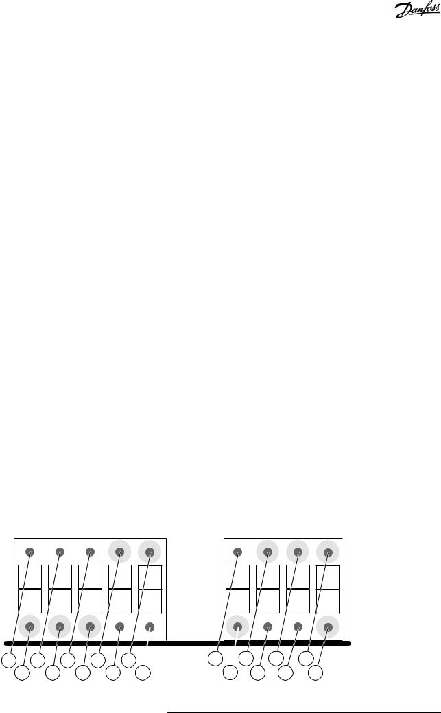
3.5.4 Option Board OPTBL
Use the Advanced safety option board OPTBL when no encoder is used to measure the speed of the motor shaft.
X3
Dout1 Dout2
X4
Din1 Din2 Din3 Din4
<![endif]>e30bi410.10
1 |
3 |
5 |
7 |
|
9 |
|
2 |
4 |
6 |
8 |
10 |
Illustration 7: The Terminals X3 and X4 of the OPTBL Option Board
11 |
13 |
15 |
17 |
12 |
14 |
16 |
18 |
30 | Danfoss A/S © 2021.06 |
AQ319736045637en-000101 / DPD01798 |
Loading...