


Danfoss KPU 74B, KPU 74, KPU 75, KPU 77, KPU Data sheet
...Data sheet
Thermostat
KPU
The KPU Thermostats are temperature controlled electrical switches, which are applied for regulation and safety monitoring of refrigeration and air conditioning systems.
KPU sensors are available with vapor charge or with adsorption charge. The Thermostats with adsorption charge are widely used to give frost protection, while vapor charged sensors are used where small differential is required.
All KPU Thermostats have a single pole double throw (SPDT) contact system. The position of the switch depends on the thermostat setting and the bulb temperature.
Features |
• Wide temperature regulating range allows use in |
|
low, medium, and high temperature refrigeration |
|
application and air-conditioning systems |
|
• Snap-action electrical contacts minimize chatter, |
|
bounce and wear, and ensure long-term electrical |
|
and mechanical reliability |
|
• Fingertip manual trip feature allows contact |
|
function testing without tools |
|
• Easily replaces other manufacturers’ thermostats |
|
• Ultra-short bounce time |
•Long operating lifetime
•Vibration and shock resistant
•SPDT switch allows NC or NO function option as well as alarm capability
•Automatic and manual reset versions available
Approvals |
UL listed for USA and Canada, file E31024 |
© Danfoss | DCS (jmn) | 2016.08 |
DKRCC.PD.CA0.F6.22 | 520H11320 | 1 |

Data sheet | Thermostat, KPU
Technical data |
|
|
|
|
Ambient temperature |
|
-40 – 122 °F, 175 °F up to 2 hours |
||
|
|
|||
|
|
|
|
|
|
Cable entry |
|
7/8 in cable entry for 1/2 in male pipe thread connection |
|
|
|
(conduit boss) |
||
|
|
|
|
|
|
|
|
|
|
|
Maximum wire dimension |
|
10 AWG |
|
|
|
|
|
|
|
Enclosure |
|
~NEMA 1 |
|
|
|
|
|
|
|
Switch |
|
SPDT – single pole double throw |
|
|
|
|
|
|
|
|
|
|
FLA = 24 A at 120 V AC |
|
|
|
Alternating current |
24 A at 240 V AC |
|
|
|
|
|
|
|
NAM rating |
LRA 1) = 144 A at 120 V AC |
|
|
|
|
||
|
|
|
|
144 A at 240 V AC |
|
|
|
|
|
|
Contact load |
|
Direct current |
12 W pilot duty at 240 V DC |
|
|
|
|
|
|
|
|
Alternating current |
AC1: 16 A, 400 VA |
|
|
European rating |
|
|
|
|
AC3: 16 A, 400 VA |
||
|
|
|
||
|
|
(acc. to EN 60947) |
|
|
|
|
|
|
|
|
|
|
Direct current |
DC13: 12 W, 220 V control current |
|
|
|
|
|
1) LRA is rated for make only
Regulating ranges in [°F]
KPU 61 |
|
KPU 62 (room sensor) |
Vapor charge |
KPU 63
KPU 68 (room sensor)
KPU 69
KPU 62
KPU 71
|
|
|
|
|
|
|
|
|
|
|
|
|
|
|
|
KPU 73 |
Adsorption charge |
||||||||
|
|
|
|
|
|
|
|
|
|
|
|
|
KPU 74
KPU 75
KPU 77
|
|
|
|
|
|
|
|
|
|
|
|
|
|
|
|
-50 |
0 |
50 |
|
|
|
|
|
100 |
150 |
||||||
2 | 520H11320 | DKRCC.PD.CA0.F6.22 |
© Danfoss | DCS (jmn) | 2016.08 |
Data sheet | Thermostat, KPU |
|
|
|
|
|
|
|
|
|
|
||
Ordering |
|
|
|
|
|
|
|
|
|
|
|
|
|
|
|
|
|
Differential |
|
Max. |
|
|
|
||
|
|
|
|
|
|
|
|
|
|
|||
|
|
|
Bulb |
|
|
|
|
|
Reset |
Capillary |
|
|
|
|
|
Range |
at lowest |
at highest |
bulb |
Code no. |
|||||
|
Type |
|
type |
function |
tube length |
|||||||
|
|
|
temperature |
temperature |
temp. |
|
||||||
|
|
|
|
|
setting |
setting |
|
|
|
|
||
|
|
|
|
|
|
|
|
|
|
|
||
|
|
|
|
[°F] |
[°F] |
[°F] |
[°F] |
|
[in] |
|
||
|
|
|
|
|
|
|
|
|
|
|
|
|
|
Vapour 1) |
|
|
|
|
|
|
|
|
|
|
|
|
KPU 61 |
|
A |
-20 – 60 |
10 – 40 |
2.5 – 13 |
250 |
auto. |
80 |
060L5201 |
||
|
|
|
|
|
|
|
|
|
|
|
||
|
KPU 61 |
|
B |
-20 – 60 |
10 – 40 |
2.5 – 13 |
250 |
auto. |
80 |
060L5203 |
||
|
|
|
|
|
|
|
|
|
|
|
||
|
KPU 61B |
|
B |
-20 – 60 |
fixed 11 |
fixed 3.5 |
250 |
man. 3) |
80 |
060L5204 |
||
|
KPU 61B |
|
B |
-20 – 60 |
fixed 11 |
fixed 3.5 |
250 |
man. 3) |
200 |
060L5205 |
||
|
KPU 62 |
|
C1 |
-20 – 60 |
10 – 40 |
2.5 – 13 |
250 |
auto. |
room sensor |
060L5206 |
||
|
|
|
|
|
|
|
|
|
|
|
||
|
KPU 61 |
|
B |
-20 – 60 |
10 – 40 |
2.5 – 13 |
250 |
auto. 4) |
80 |
060L5210 |
||
|
KPU 63 |
|
A |
-60 – 15 |
18 |
– 125 |
5 |
– 15 |
250 |
auto. |
80 |
060L5213 |
|
|
|
|
|
|
|
|
|
|
|
|
|
|
KPU 63 |
|
B |
-60 – 15 |
18 |
– 125 |
5 |
– 15 |
250 |
auto. |
80 |
060L5214 |
|
|
|
|
|
|
|
|
|
|
|
|
|
|
KPU 68 |
|
C1 |
25 – 95 |
8 |
– 45 |
3 |
– 13 |
250 |
auto. |
room sensor |
060L5215 |
|
|
|
|
|
|
|
|
|
|
|
|
|
|
KPU 69 |
|
B |
25 – 95 |
8 |
– 45 |
3 |
– 13 |
250 |
auto. |
80 |
060L5217 |
|
|
|
|
|
|
|
|
|
|
|
|
|
|
Adsorption 2) |
|
|
|
|
|
|
|
|
|
||
|
KPU 62 |
|
C2 |
-20 – 60 |
9 |
– 36 |
3 |
– 14 |
175 |
auto. 4) |
room sensor |
060L5207 |
|
KPU 73 |
|
E3 |
-15 – 60 |
6.5 – 32 |
5 – 50 |
175 |
auto. |
80 |
060L5208 |
||
|
|
|
|
|
|
|
|
|
|
|
|
|
|
KPU 73 |
|
E1 |
-15 – 60 |
22 |
– 125 |
15 – 45 |
175 |
auto. |
80 |
060L5209 |
|
|
|
|
|
|
|
|
|
|
|
|
||
|
KPU 73B |
|
E3 |
-15 – 60 |
fixed 6 |
fixed 6 |
175 |
man. 3) |
80 |
060L5211 |
||
|
KPU 73 |
|
D |
-15 – 60 |
6 |
– 35 |
5 |
– 32 |
175 |
auto. |
80 |
060L5212 |
|
|
|
|
|
|
|
|
|
|
|
|
|
|
KPU 71 |
|
E2 |
25 – 70 |
5.5 – 18 |
4 |
– 16 |
175 |
auto. |
80 |
060L5218 |
|
|
|
|
|
|
|
|
|
|
|
|
||
|
KPU 71B |
|
E2 |
25 – 70 |
fixed 5 |
fixed 5 |
175 |
man. 3) |
80 |
060L5216 |
||
|
KPU 74 |
|
E1 |
0 – 80 |
9 |
– 35 |
9 |
– 35 |
175 |
auto. |
80 |
060L5219 |
|
|
|
|
|
|
|
|
|
|
|
||
|
KPU 74B |
|
E1 |
0 – 80 |
fixed 10 |
fixed 10 |
175 |
man. 3) |
80 |
060L5220 |
||
|
KPU 75 |
|
F |
30 – 95 |
6 |
– 29 |
4.5 |
– 21.5 |
230 |
auto. |
80 |
060L5221 |
|
|
|
|
|
|
|
|
|
|
|
|
|
|
KPU 77 |
|
E3 |
60 – 140 |
6 |
– 18 |
6.3 – 18 |
265 |
auto. |
80 |
060L5223 |
|
|
|
|
|
|
|
|
|
|
|
|
|
|
1) Bulb must be installed in colder position than thermostat housing and capillary tube.
2) Bulb can be placed warmer or colder than thermostat housing and capillary tube, but variations from 70 °F
ambient temperature will influence the scale accuracy.
3) Manual minimum reset. Marked with letter B. Fixed differential. These controls have no hand knob.
4) With manual switch and top plate.
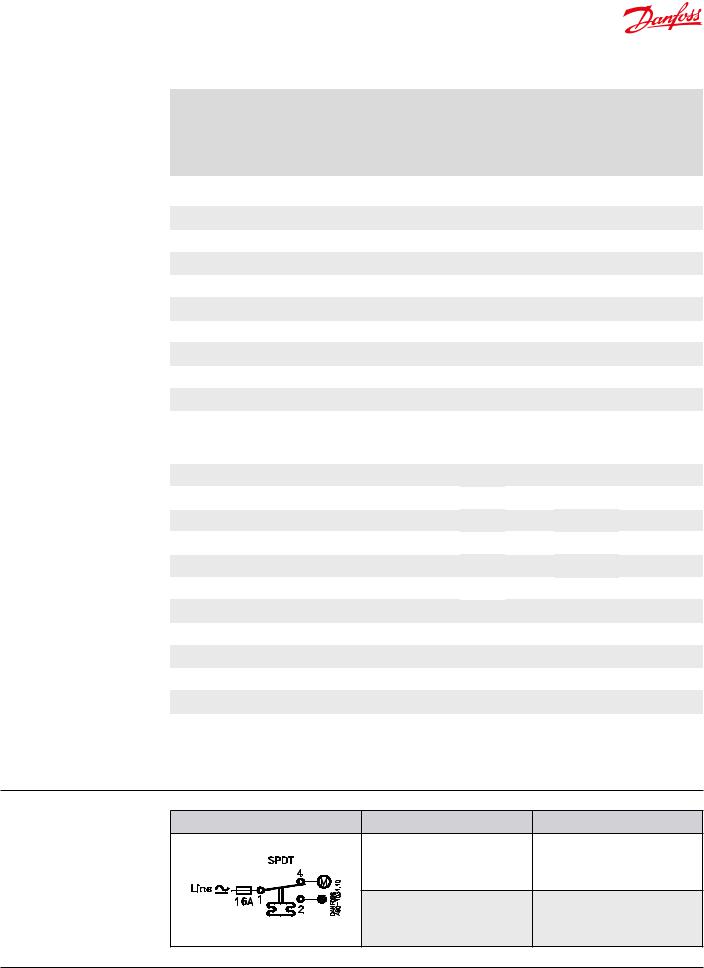
Contact system |
Switch type – single pole double throw |
Switch action |
Applicaton |
|
|||
|
|
1. Terminals 1 – 4 close high and |
|
|
|
open low |
1. Low temperature cut-out |
|
|
Terminals 1 – 2 can be used as |
|
|
|
|
|
|
|
low temperature alarm |
|
|
|
2. Terminals 1 – 2 open high and |
|
|
|
close low |
2. High temperature cut-out |
|
|
Terminals 1 – 4 can be used as |
|
|
|
|
|
|
|
high temperature alarm |
|
© Danfoss | DCS (jmn) | 2016.08 |
DKRCC.PD.CA0.F6.22 | 520H11320 | 3 |
 Loading...