


Installation Guide
Electronic Heat Cost Allocator INDIV-X-10V, INDIV-X-10W Radio
0.0 |
Table of Contents |
|
|
|
|
|
|
1. |
General . . . . . . . . . . . . . . . . . . |
. |
3 |
2.6 |
Error . . . . . . . . . . . . . . . . . . . |
. . |
. . . . . 21 |
1.1 |
Introduction . . . . . . . . . . . . . . . . . . . . . |
. |
3 |
2.6.1 |
Description of the Function Control . . . . |
. . |
. . . . . 21 |
1.2 |
Application . . . . . . . . . . . . . . . . . . . . . |
. |
. 3 |
2.6.2 |
List of Errors . . . . . . . . . . . . . . . |
. . |
. . . . . 22 |
|
|
|
|
2.7 |
Radio Standby – Radio-HCA INDIV-X-10W . |
. . . . . . . 22 |
|
2. |
Specification . . . . . . . . . . . . . . . . |
|
. 4 |
2.7.1 |
Sleeping Mode . . . . . . . . . . . . . . |
. . . . . . . 22 |
|
2.1 |
General Description . . . . . . . . . . . . . . . . . |
. |
. 4 |
2.7.2 |
Installation Mode . . . . . . . . . . . . . . . . . . . 22 |
||
2.1.1 |
Type . . . . . . . . . . . . . . . . . . . . . . . . . |
. |
4 |
2.7.3 |
Operation Mode . . . . . . . . . . . . . |
. . |
. . . . . 23 |
2.1.2 |
Design . . . . . . . . . . . . . . . . . . . . . . . . |
. |
4 |
3. |
Installation . . . . . . . . . . . . . . . . . 24 |
||
2.1.3 |
Characteristics . . . . . . . . . . . . . . . . . . . . |
. |
4 |
||||
2.1.4 |
Display . . . . . . . . . . . . . . . . . . . . . . . |
. |
. 5 |
3.1 |
Introduction . . . . . . . . . . . . . . . |
. . |
. . . . . 24 |
2.1.5 |
Electronics . . . . . . . . . . . . . . . . . . . . . . |
. |
5 |
3.2 |
DIN Standard Requirements for the Installation |
. . . . . 24 |
|
2.1.6 |
Versions . . . . . . . . . . . . . . . . . . . . . . . |
. |
5 |
3.3 |
General Restrictions . . . . . . . . . . . . . . . . . . 25 |
||
2.1.7 |
Optical Interface . . . . . . . . . . . . . . . . . . . |
. |
5 |
3.4 |
Operating Range . . . . . . . . . . . . . |
. . |
. . . . . 25 |
2.1.8 |
Radio Transmission . . . . . . . . . . . . . . . . . . |
. |
5 |
3.5 |
Installation to the Radiator . . . . . . . . |
. . |
. . . . . 26 |
2.2 |
Operating mode . . . . . . . . . . . . . . . . . . . |
. |
6 |
3.6 |
Wall-Mounting . . . . . . . . . . . . . . |
. . |
. . . . . 27 |
2.2.1 |
Cycle Time . . . . . . . . . . . . . . . . . . . . . . |
. |
6 |
3.7 |
Installation of Fastening-Parts Kits . . . . . |
. . . . . . 28 |
|
2.2.2 |
Single Sensor Version with Start Sensor . . . . . . . . |
. |
6 |
3.7.1 |
Installation to Sectional Radiator . . . . . |
. . |
. . . . . 28 |
2.2.3 |
Double Sensor Version . . . . . . . . . . . . . . . . |
. |
6 |
3.7.2 |
Wall-Mounting - Sectional Radiator . . . . |
. . |
. . . . . 28 |
2.2.4 |
Comparison of the Measuring Principles . . . . . . . |
. |
. 7 |
3.7.3 |
Installation to Folded Radiator . . . . . . . |
. . . . . . 29 |
|
2.2.5 |
Temperature Measurement and Calculation . . . . . . |
. |
7 |
3.7.4 |
Wall-Mounting – Folded Radiator . . . . . |
. . |
. . . . . 30 |
2.2.6 |
Calculation of the Displayed Consumption Value . . . |
. |
. 8 |
3.7.5 |
Installation to Panel-Type Radiator . . . . . |
. . . . . . 31 |
|
2.2.7 |
Start of Counting . . . . . . . . . . . . . . . . . . . |
. |
9 |
3.7.6 |
Wall-Mounting - Panel-Type Radiator . . . |
. . |
. . . . . 32 |
2.3 |
Display and Additional Functions . . . . . . . . . . . |
. 10 |
3.7.7 |
Installation to Panel-Type Radiator |
|
|
|
2.3.1 |
The Menu Sequences of the Digital Display . . . . . . |
. 10 |
|
with Front Convection Plate . . . . . . . . |
. . . . . . 33 |
||
2.3.2 |
The Digital Displays . . . . . . . . . . . . . . . . . |
. |
12 |
3.7.8 |
Bathroom radiator – Towel rails . . . . . . |
. . |
. . . . . 34 |
2.3.3 |
Rolling Digital Display . . . . . . . . . . . . . . . . |
. |
15 |
3.7.9 |
Sectional radiator wide . . . . . . . . . . |
. . |
. . . . . 35 |
2.3.4 |
Energy-Saving Night Mode between 20.00 and 6.00 h . |
. 16 |
3.8 |
Overview mounting accessories . . . . . . |
. . . . . . 36 |
||
2.3.5 |
Communication Indicator . . . . . . . . . . . . . . |
. 16 |
3.9 |
Mounting and Sealing . . . . . . . . . . . |
. . |
. . . . 37 |
|
2.3.6 |
Real Time Clock and Calendar . . . . . . . . . . . . |
. |
16 |
4. |
Commissioning . . . . . . . . . . |
. . . . . 38 |
|
2.3.7 |
Readout . . . . . . . . . . . . . . . . . . . . . . . |
. 17 |
|||||
2.3.8 |
Check Code . . . . . . . . . . . . . . . . . . . . . . 17 |
5. |
Readout . . . . . . . . . . . . . . . . . . . 39 |
||||
2.3.9 |
Change of Battery . . . . . . . . . . . . . . . . . . |
. |
18 |
||||
2.3.10 |
Protection against Outside Influences . . . . . . . . . . . . . . . . . |
. . 18 |
5.1 |
Manual Readout . . . . . . . . . . . . . |
. . |
. . . . . 39 |
|
2.4 |
Special Functions . . . . . . . . . . . . . . . . . . |
. |
19 |
5.2 |
Readout over the Optical Interface . . . . . |
. . . . . . 39 |
|
2.4.1 |
Suppression of Summer Counting . . . . . . . . . . |
. |
19 |
5.2.1 |
Optical Probe . . . . . . . . . . . . . . . . . . . . . 39 |
||
2.4.2 |
Programmable Start Temperature of |
|
|
5.2.2 |
Transmission Protocol . . . . . . . . . . . . . . . . . 39 |
||
|
Summer and Winter period . . . . . . . . . . . . . . |
. 19 |
5.2.3 |
Timing of the Optical Interface . . . . . . |
. . |
. . . . . 40 |
|
2.4.3 |
Annual Reset of the Values . . . . . . . . . . . . . . |
. 19 |
5.2.4 |
Frames of the Optical Readout . . . . . . . |
. . . . . . 41 |
||
2.4.4 |
Unit Scale and Product Scale . . . . . . . . . . . . . |
. 19 |
5.2.5 |
Remote Radio Readout . . . . . . . . . . |
. . |
. . . . . 43 |
|
2.5 |
Parameterisation . . . . . . . . . . . . . . . . . . . |
. 21 |
5.2.6 |
Stationary Readout . . . . . . . . . . . . . . . . . . . . . . . . |
. . . . |
. . . . . . . . . 44 |
|
Danfoss Heating |
VIIGC102 |
1 |

Installation Guide Electronic Heat Cost Allocator INDIV-X-10V, INDIV-X-10W Radio
0.0 Table of Contents
5.2.7 Timing of Radio Transmission . . . . . . . . . . . . . . 44
5.2.8 Frame of the Radio Transmission . . . . . . . . . . . . 45
6. Rating factors . . . . . . . . . . . . . . . . 46
6.1Taking Measurements . . . . . . . . . . . . . . . . . 46
6.1.1 Rating of Radiators of Over Length or
High Nominal Output . . . . . . . . . . . . . . . . . 46 6.1.2 Rating of Radiator . . . . . . . . . . . . . . . . . . . 47 6.2 Table of Rating factors . . . . . . . . . . . . . . . . . 48
7. Technical Data . . . . . . . . . . . . . . . . 50
7.1 Dimensional Drawing . . . . . . . . . . . . . . . . . 51
8.Enclosure . . . . . . . . . . . . . . . . . . 52
8.1 |
Enclosure 1 . . . . |
. |
. |
. . |
. . |
. . |
. . |
. . |
. . |
. . |
. |
. |
52 |
8.2 |
Enclosure 2 . . . . |
. |
. |
. . |
. . |
. . |
. . |
. . |
. . |
. . |
. |
. |
53 |
8.3Temperature Limits acc. to EN 834 . . . . . . . . . . . 54
8.4Calculation of Temperature – Interpolation Table . . . . 55
8.5Rating factors acc. to EN 834 . . . . . . . . . . . . . . 56
2 |
VIIGC102 |
Danfoss Heating |

Installation Guide Electronic Heat Cost Allocator INDIV-X-10V, INDIV-X-10W Radio
1.General
1.1Introduction
This installation guide is used for the users and the service personnel of the Danfoss heat cost allocators. It describes the handling of the heat cost allocator INDIV-X-10V and the radio heat cost allocator INDIV-X-10W. Since the measuring functions are the same for both heat cost allocators the descriptions in this guide apply for both versions. In case of deviations, a special note is made to this end.
Primarily, the installation of the heat cost allocator to the most common radiator types is described. Apart from the information on the installation of the heat cost allocator, basic information (rating of heat cost allocators) is given and special features of our devices (design, function, installation) are described in this guide as well.
1.2Application
The heat cost allocator is an accessory measuring device to record the heat output of radiators in units.
Units are apartments, office-, and business-, commercial or industrial premises where the heat is supplied by a conjoint central heating system or via a conjoint district heating station.
The entity of the units forms a billing unit.
If one billing unit consists of units with typical differences (e.g. technical differences such as different heating systems or different consumptions of e.g. industrial premises and apartments), a sub-division of the billing unit in unit groups may be necessary.
Each radiator is equipped with a heat cost allocator which records and assesses the heat output of the radiator and displays the consumption value. The consumption value is the basis for allocating the heating costs to each unit which is necessary for the annual billing of the heating costs.
Danfoss Heating |
VIIGC102 |
3 |
Installation Guide Electronic Heat Cost Allocator INDIV-X-10V, INDIV-X-10W Radio
2.Specification
2.1General Description
2.1.1 Type
The electronic heat cost allocators Danfoss INDIV-X-10V / INDIV- X-10W operate either according to the single sensor principle with start sensor or the double sensor principle. The device has been developed and approved in accordance with the European Standard EN 834:2013.
2.1.2 Design
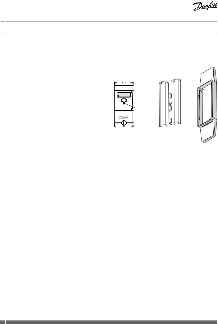
The heat cost allocator consists of a microprocessor, a lithium battery, two temperature sensors, a heat conducting aluminium back plate, a multi-functional display and a plastic housing. The measuring circuit consists of the temperature sensors,
the analogue-digital conversion, the reference resistance for standardising the measuring transformation and the microprocessor for accessing the radiator heat output. During each measuring the circuit tolerances are eliminated with a
reference resistance and the heat cost allocator carries out an automatic self-test.
2.1.3 Characteristics
•Measuring by two temperature sensors, radiator and ambient temperature sensor (NTC-resistor)
•Optional measuring principle: 1 sensor mode with start sensor or two sensor mode
•Unit scale or product scale
•Recording of cumulated heat consumption on the annual set day
•Recording of 36 monthly values or 18 monthly and half monthly values
•Optical interface for the readout of the data and programming
•Readout via radio optional with a mobile radio modem or directly by the billing office over the radio central installed outside the unit
•User-friendly operation by push button
•6-digit and high-contrast LCD display
•Check code for postcard mail-in method
•Remote sensor version with 1.5 m cable
•Standard aluminium back plate for nearly all existing bolts with common dimensions and installation possibilities – thus easy installation (no cutting and welding of bolts necessary)
•Snap-on blind to cover colour shadows for increased aesthetics
•Safe operation and fraud detection
•Factory seal protecting against unauthorized manipulation
•Possibility to use seal sticker as second seal for further protecting against manipulation
•Lithium battery with a capacity of up to 10+1 years
•Meets EN 834:2013.
|
: : |
LCD-Display |
|
|
|
|
|
Optical |
|
|
Interface |
|
|
Push Button |
|
|
Seal |
Standard aluminium back plate for nearly all existing bolts with common dimensions and mounting possibilities – thus easy installation.
Snap-on blind to cover colour shadows for increased aesthetics.
4 |
VIIGC102 |
Danfoss Heating |

Installation Guide Electronic Heat Cost Allocator INDIV-X-10V, INDIV-X-10W Radio
2.Specification
2.1.4 Display |
|
|
|
|
||
The heat cost allocator has a LCD-display with 6 large main digits |
|
|
|
|
||
|
: : |
|
||||
on the right and 2 smaller digits on the left as well as two special |
Display with all active segments |
|||||
|
|
|||||
symbols and one communication indicator. The main digits are |
|
|
|
|||
separated by four decimal points. Below, please find the display |
|
|
|
|
||
|
|
|
|
|||
segments: |
|
|
|
|
||
Normally, the heat cost allocators INDIV-X-10V / INDIV-X-10W are |
|
|
|
|
||
supplied with switched-off LCD-display. On request, the heat cost |
|
|
|
|
||
allocators can also be supplied with permanent LCDdisplay. |
|
|
|
|
||
2.1.5 Electronics |
|
|
|
|
||
The device has an electrical circuitry with an 8-Bit-CMOS-micro |
|
|
|
|
||
controller of the latest generation H8-300L with extremely low |
|
|
|
|
||
current |
consumption operating at a voltage as from 1.8 V. |
|
|
|
|
|
The temperature measuring circuit with automatic self-calibration measures the discharging time of a capacitor. The accuracy of the measuring circuit is independent of the supply voltage.
2.1.6 Versions
•Heat cost allocator INDIV-X-10V with optical interface, standard device
•Heat cost allocator INDIV-X-10VT with optical interface, remote sensor device with 1.5 m cable
•Radio heat cost allocator INDIV-X-10W with optical interface, standard device
•Radio heat cost allocator INDIV-X-10WT with optical interface, remote sensor device with 1.5 m cable.
2.1.7 Optical Interface
With a standardised optical probe the consumption and configuration values can be transferred directly to a computer. With the radio heat cost allocator INDIV-X-10W all consumption values can thus be readout over the optical interface and over radio. The data are transmitted in M-bus-format acc. to EN1434. Authorised personnel can alter the configuration of the device over the optical interface with an optical probe.
2.1.8 Radio Transmission
The radio heat cost allocator INDIV-X-10W features a transceiver circuit in the 433 MHz band with integrated antenna. With the radio system, proven since more than 10 years; it is possible to readout the consumption values via a mobile radio modem or via a radio central installed directly in the office. The radio system is a bidirectional system, i.e. the radio heat cost allocator is only called from a mobile PDA or a radio central upon request to send its data. It is a great advantage that this system allows the alteration of the parameters over radio.
Danfoss Heating |
VIIGC102 |
5 |
Installation Guide Electronic Heat Cost Allocator INDIV-X-10V, INDIV-X-10W Radio
2.Specification
2.2Operating mode
2.2.1 Cycle Time
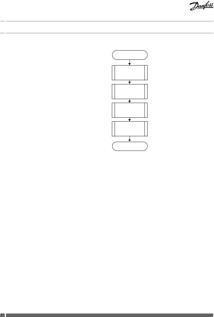
The heat cost allocators INDIV-X-10V / INDIV-X-10W operate in a cycle of 4 minutes. Most of the time, the device is in sleeping
mode. Every 4 minutes the device is set into operation and operates according to the adjoining diagram.
The clock-pulse generator is a counter which is completely independent from the rest of the programme. This counter is designed in a way so that it is impossible to stall the cycle or to skip one or more cycles.
Each cycle follows the adjoining diagram. The measuring and calculating processes are explained in detail later.
The tasks carried out during one cycle are taking approx. 200 ms. This means that the device is in sleeping mode more than 99.8 % of the time. It can be set into operation between two cycles over the optical probe or by pushing the button. In this case it carries out the requested task and then returns to sleeping mode.
In case an optical probe is connected or the button is pushed during the course of the cycle, the respective value is readout at the end of the cycle.
The button can be pushed for an indefinite period of time and the optical probe can be left in its position since the normal function of the device is not impaired by an influence from outside.
2.2.2 Single Sensor Version with Start Sensor
The start sensor of the single sensor version serves as an ambient temperature sensor which mainly functions during the heating up period.
The start temperature is the threshold temperature of the radiator at which the device always starts to carry out energy ratings. For these ratings, the measured radiator temperature and an assumed ambient temperature of 20° C are used as calculation basis.
2.2.3 Double Sensor Version
For the double sensor version basically the same specifications apply as for the single sensor ver-sion with start sensor. However,
for calculating the room temperature the real temperature, meas-ured by the ambient temperature sensor (corrected via the corresponding radiator-dependent„Kair-value“), is used as the basis.
2.2.3.1 Heat Accumulation Mode
In order to avoid faulty measuring due to heat accumulation (e.g. in case the radiator is hidden by panels), the device switches from a defined ambient temperature (e.g. 28°C) to the one sensor mode and calculates with an ambient temperature of 20° C.
Start of cycle
Update time and date
Measuring and calculation of the temperatur
Calculation of the new consumtion value
Update display
End of cycle
6 |
VIIGC102 |
Danfoss Heating |

Installation Guide Electronic Heat Cost Allocator INDIV-X-10V, INDIV-X-10W Radio
2.Specification
2.2.4 Comparison of the Measuring Principles
Single sensor device with start sensor measuring principle
For heating systems with tmmin ≥ 55 °C
The heat cost allocator calculates with a set reference temperature of 20 °C
Application:
Single sensor devices with start sensor are used in areas where normal ambient temperatures are given. For low temperature heating systems the double sensor device is recommended.
For radiators which are covered or blocked by fixtures, normally the single sensor devices are used because the double sensor device is not in a position to capture the current ambient temperature due to the heat accumulation.
The processes for determining the K-value for the single sensor device with start sensor and the double sensor device are identical . It is only the measuring principle that is different.
2.2.5 Temperature Measurement and Calculation
The temperature is measured with an NTC – resistor. For the resistance measurement the dis-charging time of the capacitor is measured. The measurement is carried out as follows:
2.2.5.1 Measuring of a Resistor, Principle
1.Charging of the capacitor
2.Discharging of the capacitor through the resistance which is to be measured. At the same time a 16-bit-timer starts with the discharge to measure the discharging time.
3.As soon as the voltage on the capacitor terminals reaches a certain value, an interrupt is in-duced and the timer stops. At the same time the discharging of the capacitor is stopped as well.
After the three mentioned stages, the timer provides a 16-bit- value which corresponds to the dis-charging time of the capacitor through the resistance which is to be measured. In case the resistance is known (reference resistance), the constant ratio between discharging time and resistance can be assessed.
Double sensor measuring principle
For heating systems with tmmin ≥ 35 °C
The heat cost allocator calculates with a variable reference
temperature Tair temperature
Application:
Double sensor devices are used in areas where precise measuring of the ambient temperature is necessary and/or in low temperature heating systems.
Radiators which are covered or blocked by fixtures are detected automatically by the double sensor system which then switches over internally to the single sensor mode.
Within one billing unit, only one measuring principle (either single sensor measuring principle with start sensor or double sensor measuring principle) can be used. Mixed fitments or the use of different types of devices in the same billing unit is therefore also not allowed.
Danfoss Heating |
VIIGC102 |
7 |

Installation Guide Electronic Heat Cost Allocator INDIV-X-10V, INDIV-X-10W Radio
2.Specification
2.2.5.2 Calculation of the Value of an Unknown Resistance
(e.g. sensor resistance)
The capacitor C is loaded at constant current. The interrupt at the end of the discharge is triggered by the same threshold voltage (a fraction of the discharge voltage). If these two conditions are met, the discharge time is directly proportional to the resistance. With a reference resistance Rref whose exact value is known, it is now possible to calculate the unknown resistance value Rx with the following equation:
From this equation the self-calibration of the converter can be derived, which is given by measuring the discharging time through the reference resistance.
2.2.5.3 Measuring of the Radiator and Ambient Temperature
The following measurements are carried out during one cycle:
1.Measuring of the reference resistance Rref
2.Measuring of the ambient temperature sensor NTCA
3.Measuring of the radiator temperature sensor NTCR
The measuring values are calculated with the following formula:
The reference resistance value is defined ex works with a tolerance of 0.5% with 50 ppm. The reference resistance features an excellent temperature and long-term stability.
The capacitor value and the threshold voltage have to remain stable over the whole cycle. However, they can vary at the mediumor long term without causing any failures because the self-calibration of the converter is repeated in every cycle while measuring the reference resistance.
2.2.6 Calculation of the Displayed Consumption Value
The value displayed on the heat cost allocator is calculated as follows:
Single sensor device |
Double sensor device |
Explanation: TH TQA K
Temperature of the radiator surface in [°C] Ambient temperature in [°C]
Displayed consumption value, without unit Correction factor
Unit scale: |
K = 1, set, transmitted via readout telegram 0. |
Product scale: |
Acc. to entry K = KC * KQ |
! see also in chapter 6.1.2 Rating of radiators !
8 |
VIIGC102 |
Danfoss Heating |

Installation Guide Electronic Heat Cost Allocator INDIV-X-10V, INDIV-X-10W Radio
2.Specification
2.2.7 Start of Counting
The updating (increment) of the consumption value is carried out under the following conditions:
During winter period (heating period):
(TR ≥ 25 °C)
OR
(TR ≥ 20 °C ) AND (TR - TA ≥ ΔTMIN)
During summer period (off heating period):
(TR ≥ 35 °C)
OR
(TR ≥ 20 °C ) AND (TR - TA ≥ ΔTMIN)
Explanation: TR |
Radiator temperature |
TA |
Ambient temperature |
ΔTMIN |
Minimum temperature difference between |
|
radiator and room |
|
3K for standard device (winter heating |
|
period standard setting) |
|
4K for remote sensor device (summer |
|
heating period standard setting) |
Danfoss Heating |
VIIGC102 |
9 |
Installation Guide Electronic Heat Cost Allocator INDIV-X-10V, INDIV-X-10W Radio
2.Specification
2.3Display and Additional Functions
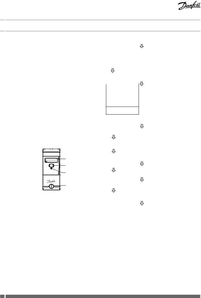
2.3.1 The Menu Sequences of the Digital Display
The menu sequences
Ex factory all menu sequences are activated. With the software INDIV-X-VISUAL-CONF the order of the menu sequences 1 - 7 can be changed in any order. However the order within the individual menu sequences 1 – 7 can-not be changed. It is also possible to hide individual menu sequences so that they are not visible to the end-user.
When reading out over the optical interface or via radio the complete set of data is always readout and transferred.
Operation of the Push Button
When pushing the button briefly the digital display always goes to the next menu sequence.
When pushing the button in one menu sequence for 2 seconds the individual values within the selected menu sequence can be accessed. When the last value within one menu sequence has been displayed, the next menu sequence can be reached by pushing the button again.
If the button is not pushed for 2 minutes, the digital display returns to the cumulated consumption value.
|
: : |
LCD-Display |
|
|
|
|
|
Optical |
|
|
Interface |
|
|
Push Button |
|
|
Seal |
|
Comsumption value |
|
Display position |
|
|
|
|
|
|
|
Long key press |
|
Set day value |
|
|
|
|
||
|
|
|
|
|
Check code |
|
|
|
|
|
|
|
Value on December 31st |
|
|
|
or before the reset to 0 |
|
|
|
Short key press |
|
|
|
|
|
Display position |
|
Current time |
|
|
|
|
|
|
|
|
|
Long key press |
|
Current date |
|
|
|
Set day date |
|
|
|
|
|
|
|
Date of opening of the |
|
|
|
device |
|
|
|
Commissionen date |
|
|
Cumulated duration of the opening of the device
 Short key press
|
Set day value |
|
Display position |
|
|
Long key pres |
|
|
|
|
|
|
Check code |
|
|
|
|
|
|
|
Short key press |
|
|
|
|
|
Display position |
|
Check code |
|
|
|
|
|
|
|
|
|
|
|
Short key press |
|
|
|
|
|
Display position |
|
Monthly values |
|
|
|
|
|
|
|
|
|
Long key press |
|
|
|
|
|
Short key press |
|
|
|
|
|
Display position |
|
Radiator temperature |
|
|
|
|
Long key pres |
|
|
|
|
|
|
Ambiant temperature |
|
|
|
|
|
|
|
Short key press |
|
|
|
|
|
Display position |
|
Segment test |
|
|
|
|
|
|
|
|
|
Long key pres |
|
Identi cation number |
|
|
|
|
||
|
|
|
|
|
Measuring principle + |
|
|
|
software version |
|
|
|
|
|
|
10 |
VIIGC102 |
Danfoss Heating |

Installation Guide Electronic Heat Cost Allocator INDIV-X-10V, INDIV-X-10W Radio
2.Specification
Display loops and display menu sequences – example
The display loops and display menu sequences are customized, for example, the rolling display:
And the display menu sequences:
|
|
|
|
|
|
|
|
|
|
|
|
|
|
|
|
|
|
|
|
|
unit scale |
|
|
|
|
7 S |
|
Current consumtion |
|
|
|
|
|
|
|
|
|
|
|
|
|
|
|
|
|
|
|
|
|
|
|
|
|
|
|
Date and Time |
|
|
|
: : |
7 S |
|
Set Day Value unit scale |
|
|
|
|
|
7 S |
|
|
|
|
|
||
|
|
|
||||
|
|
|
|
|
||
Check code |
|
|
|
|
|
7 S |
|
|
|
|
|
||
|
|
|
|
|
||
|
|
|
||||
|
|
|
|
|
||
Last monthly value |
|
|
|
|
|
7 S |
|
|
|
|
|
||
|
|
|
|
|
||
|
|
|
||||
|
|
|
|
|
||
|
|
|
|
|
|
|
|
|
|
|
|
|
|
|
|
|
|
|
|
|
Radiator Temperature |
|
|
|
|
. |
7 S |
Segment Test |
|
|
|
|
|
1 S |
|
|
|
|
|
||
|
|
: : |
||||
|
|
|
|
|
|
|
|
|
|
|
|
|
|
|
|
|
|
|
|
|
|
|
|
|
|
|
|
|
|
|
|
|
|
|
Error messages
|
|
|
|
|
|
|
|
|
|
|
|
|
|
|
|
Current consumtion |
|
Date and Time |
Set Day Value unit scale |
|
Check code |
|
Monthly Value |
Radiator Temperature |
|
Segment Test |
|||||
unit scale |
|
|
|
|
|||||||||||
|
|
|
|
|
|
|
|
|
|
|
|
|
|
||
|
|
|
: |
: |
|
|
|
|
|
|
|
. |
|
: : |
|
|
|
|
|
|
|
|
|
|
|
||||||
|
|
|
. . |
|
|
|
|
|
|
|
. |
|
|
|
|
|
|
|
|
||||||||||||
|
|
|
|
|
|
|
|
|
|
|
|||||
|
|
. . |
|
|
|
|
|
|
|
|
|
|
. |
||
|
|
|
|
|
|
|
|
|
|
|
|
|
|||
|
|
|
. . |
|
|
|
|
|
|
|
|
|
|
|
|
|
|
|
|
|
|
|
|
|
|
|
|
||||
|
|
|
. . |
|
|
|
|
|
|
|
|
|
|
|
|
|
|
|
|
|
|
|
|
|
|
|
|
|
|
||
|
|
|
|
|
|
|
|
|
|
|
|
|
|
|
|
|
|
|
|
|
|
|
|
|
|
|
|
|
|||
Short pression on push button (1s)
 Long pression on push button (>2s)
Danfoss Heating |
VIIGC102 |
11 |

Installation Guide Electronic Heat Cost Allocator INDIV-X-10V, INDIV-X-10W Radio
2.Specification
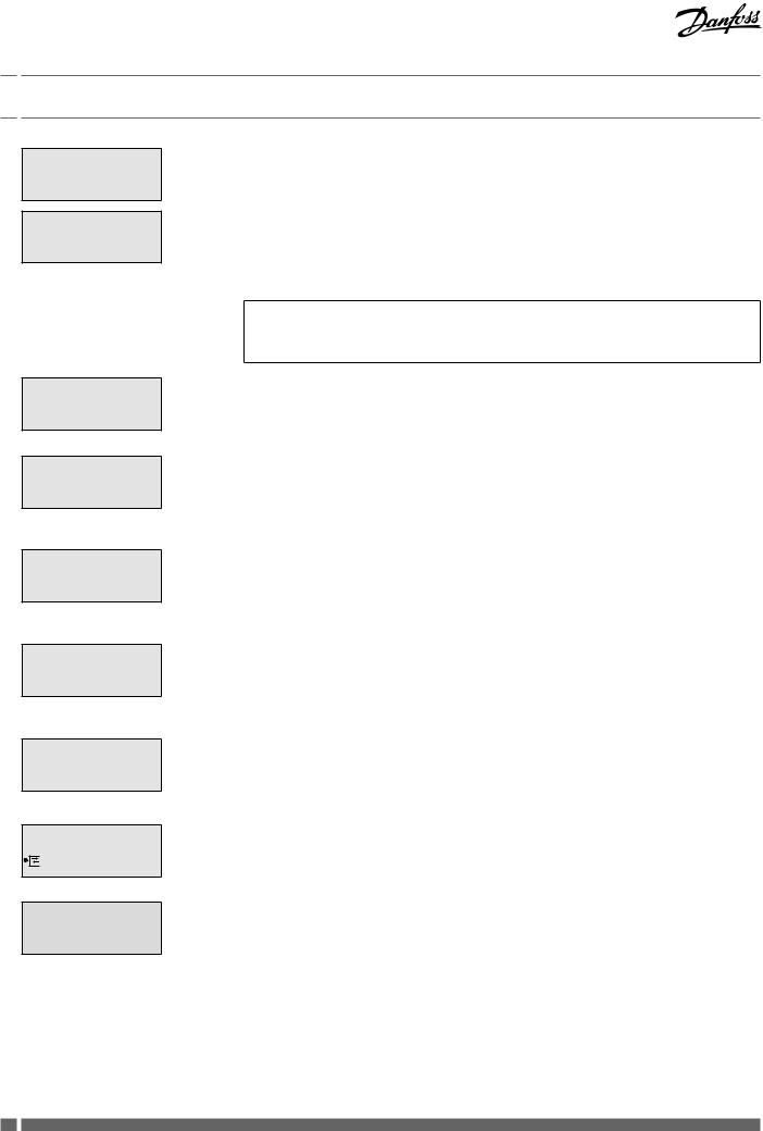
2.3.2The Digital Displays
During normal operation the display is deactivated and can be activated by pushing the button. On request, the heat cost allocator is also available with permanent display from 06:00 – 20:00 h or 24 hours a day. The consumption value is displayed.
By pushing the button and depending on the configuration of the heat cost allocator more than 50 different values can be displayed. If the button is not pushed, the display will be active for 2 minutes only. Exception: permanent display mode.
Consumption Value Unit Scale
Consumption Value Product Scale
Set Day Value
Set day Value product scale
Check Code
Consumption Value of the
Previous Heating Period


Time
:
On the display of the heat cost allocator with unit scale an index u for unit is shown on the left side. If the index u is not displayed, the heat cost allocator is equipped with the product scale.
When commissioning the device this value is 000000. When reaching the value 999999, the counting restarts automatically at 000000.
With the index ud the consumption value in unit scale recorded at midnight of the set day is displayed.
If a new device has not yet reached the programmed set day, 000000 is displayed.
With the index d the consumption value in product scale recorded at midnight of the set day is displayed.
If a new device has not yet reached the programmed set day, 000000 is displayed.
With the index cc the check code for the plausibility check of the manual readout is displayed.
With the index uI the consumption value is displayed which was recorded on December 31st or before the reset to zero.
000000 is displayed on a new device as long as a reset has not been carried out.
The current time (always winter time)
12 |
VIIGC102 |
Danfoss Heating |

Installation Guide Electronic Heat Cost Allocator INDIV-X-10V, INDIV-X-10W Radio
2.Specification
Date
. .
Set Day
. .
Date of Opening of the Device
. .
Commissioning Date
. .
Cumulated Duration of the
Opening of the Device
Identification Number

Monthly Values
Values
The current date of the heat cost allocator
It is possible to program an annual set day on which the cumulated consumption value as well as the maximal radiator temperature are recorded.
With the index Sd the programmed annual set day is displayed.
Each heat cost allocator is equipped with a manipulation protection which detects an unauthorised opening of the device after installation to the radiator. The date of the opening of the device is recorded and displayed with the index od.
With the index cd the commissioning date is displayed, i.e. the date on which the device has been activated by pushing the button or the date of commissioning programmed ex factory.
The cumulated duration in minutes during which the device was opened is detected. This display turns up only after commissioning in case the heat cost allocator was opened or removed.
With the index an 8 digit identification number is displayed. Ex factory the serial number is identical with the identification number. The first two digits of the identification number are the two small digits on the left upper side of the digital display.
The cumulated consumption values are recorded automatically at midnight on the last day of each month.
Number of monthly values: 18 or 36
The small digits on the upper left side show the number of previous monthly values. Digit 01 stands for the recent full month and digit 18 or 36 stands for the least recent month.
All monthly values are set to 000000 when the device is commissioned.
Note INDIV-X-10W radio:
The radio heat cost allocator INDIV-X-10W only transmits the first 16 monthly values via radio telegram.
Danfoss Heating |
VIIGC102 |
13 |
Installation Guide Electronic Heat Cost Allocator INDIV-X-10V, INDIV-X-10W Radio
2.Specification
Half Monthly Values
Radiator Temperature
.
The cumulated consumption values are recorded automatically at midnight on the 16th of each month.
The small digits on the upper left side indicate the number of half monthly values. Digit 41 stands for the recent half monthly value and digit 58 for the least recent half monthly value. All half monthly values are set to 000000 when the device is commissioned.
If the heat cost allocator INDIV-X-10V is programmed with 36 monthly values the menu sequences for the half monthly values are omitted.
Note INDIV-X-10W radio:
The heat cost allocator INDIV-X-10W does not transmit the half monthly values via radio telegram.
With the index tH the current radiator temperature is displayed.
Ambient Temperature
.
Maximum Radiator Temperature
of the Current Heating Period
.
Maximum Radiator Temperature
of the Previous Heating Period
.
Measuring Principle and
Software Version
.
Segment Test
 : :
: :
Error Message
With the index tA the current ambient temperature is displayed.
With the index P0 the maximum radiator temperature since the last reset or of the current heating period is displayed.
With the index P1 the maximum radiator temperature before the last reset or of the previous heating period is displayed.
With the index F1 or F2 the measuring principle is displayed . F1 = single sensor device with start sensor
F2 = double sensor device
On the right side the software version x.xx of the heat cost allocator is displayed.
Segment test of the display.
If an error is detected, Err is displayed in the first display sequence with the corresponding error message.
14 |
VIIGC102 |
Danfoss Heating |

Installation Guide Electronic Heat Cost Allocator INDIV-X-10V, INDIV-X-10W Radio
2.Specification
2.3.3 Rolling Digital Display
The EHCA INDIV-X-10V and INDIV-X-10W also feature the possibility of a rolling display between 06:00 – 20:00 h. With the software INDIV-X-VISUAL-CONF it is possible to
individualise the rolling display. Up to 7 parameters can be chosen optionally from the list below. These parameters can be combined in any order and are then shown on the rolling display.
•Consumption value
•Time
•Date
•Set day
•Set day value
•Last monthly value
•Last half monthly value
•Radiator temperature
•Ambient temperature
•Maximum radiator temperature of the current heating period or since the last reset
•Segment test
The duration of the display of the values can be chosen |
|
|
individually |
as follows: |
|
• Short duration: 1 s (set, cannot be changed) |
|
|
• Long duration: 2 - 7 s (only one value can be chosen) |
|
|
Example: |
|
|
Order and duration of display |
|
|
• Pos. 0: Error (parameter ex factory, cannot be changed |
[5 s] |
|
(only displayed in case of an error message) |
|
|
• Pos 1: Time |
[1 s] |
|
• Pos 2: Segment test |
[1 s ] |
|
• Pos 3: Consumption value |
[4 s] |
|
• Pos 4: Set day |
[1 s] |
|
• Pos 5: Set day value |
[4 s] |
|
• Pos 6: Last monthly value |
[1 s] |
|
•Pos 7: Blank (therefore no display. It is not necessary to occupy all positions)
The rolling display can also be deactivated by the INDIV-X-VISUAL-CONF, i.e. the device operates as in standard menu mode except that only these values and the values of the corresponding sub-menus that have been defined in the rolling menu can be displayed by pushing the button. After 2 minutes during which the button has not been pushed, the display goes out.
Danfoss Heating |
VIIGC102 |
15 |
Installation Guide Electronic Heat Cost Allocator INDIV-X-10V, INDIV-X-10W Radio
2.Specification
2.3.4Energy-Saving Night Mode between 20.00 and 6.00 h
If the LCD-display is activated, the heat cost allocator switches automatically to the energy-saving night mode between 20.00 and 06.00 h (winter time). During this period the LCD-display is deac-tivated and switched off generally.
2.3.5Communication Indicator 
The communication indicator displays if the heat cost allocator is currently making a calculation and/or if it communicates internally or externally over the optical or wireless interface.


If the arrow of the communication indicator points inwardly internal communication takes place over the optical or wireless interface.
If the arrow of the communication indicator points outwards external communication takes place over the optical or wireless interface.
If the frame of the communication indicator appears the heat cost allocator is carrying out a measuring or a calculation.
2.3.6 Real Time Clock and Calendar
The device has a 24 h real time clock and a calendar. However, the change from summer to winter time is not taken into account. The calendar is programmed until December 31 2099, including all leap years. The real time clock as well as the date of the heat cost allocator can be readout over the optical interface or via radio and if necessary be updated.
If the current date and time have to be updated over the optical interface or via radio, it is necessary to check the date of the computer first. Date and time of the device aim at those of the computer. If the reading/programming
device (computer/PDA/ Smart Phone) has a wrong time, this time will be programmed into the heat cost allocator and suddenly no longer be reached at the usual time, because the time of the heat cost allocator possibly is shifted by several hours.
16 |
VIIGC102 |
Danfoss Heating |

Installation Guide Electronic Heat Cost Allocator INDIV-X-10V, INDIV-X-10W Radio
2.Specification
2.3.7 Readout
The current and monthly values recorded by the heat cost allocator INDIV-X-10V and INDIV-X-10W as well as several other parameters can be readout over the optical interface or also over radio with the heat cost allocator INDIV-X-10W (see description chapter 5).
The following parameters are transmitted:
•Identification number (information in header)
•Error
•Software version
•Date and time
•Consumption value
•Kc-value x KQ-value
•Current radiator temperature
•Current ambient temperature
•Date of the opening of the housing
•Cumulated duration of the opening of the housing in minutes
•Date of commissioning
•Set day
•Set day value
•Value of previous heating period
•Maximum radiator temperature of current heating period
•Maximum radiator temperature of previous heating period
•Monthly values
•Half monthly values
•Serial number
2.3.8Check Code
A special additional feature of the electronic heat cost allocator INDIV-X-10V is the check code function for the postcard mail-in method.
With especially developed algorithms a 6 digit check code is generated out of several device data. With this check code the values stated on the postcards mailed-in by tenants can be cross checked.
For this check
•the date
•the current consumption value
•the set day value and
•the check code
are required.
For the verification of the check code Danfoss places all necessary tools (programmes, formulas) at the disposal of the authorised personnel.
Danfoss Heating |
VIIGC102 |
17 |

Installation Guide Electronic Heat Cost Allocator INDIV-X-10V, INDIV-X-10W Radio
2.Specification
2.3.9 Change of Battery
The battery of the heat cost allocator is soldered. The lithium battery is not rechargeable. A change of battery is not planned. Therefore the heat cost allocators have to be replaced after 10 years.
Disposal
It is mandatory to dispose of the heat cost allocator environmentally friendly or to return it after use to the manufacturer for appropriate disposal to ensure that the components are recycled in accordance with the battery and electronic scrap regulations. Should you do the disposal yourself please get information from your local authority on the recycling possibilities.
2.3.10 Protection against Outside Influences
2.3.10.1 Seal and seal sticker
The heat cost allocator is closed with a seal which cannot be removed without damaging it. Thus it is impossible to open the device unnoticed.
A seal sticker as second seal is used for further protecting against manipulation. After mounting, the seal sticker is fixed between housing of heat cost allocator and aluminium back plate. Heat cost allocator cannot be removed from aluminium back plate without damaging a sticker.
After installation, the electronic part of the device is no longer accessible. The digital display, the push button and the optical interface are covered by a sight glass. It is impossible to access the inside of the device through these openings without damaging the sight glass.
2.3.10.2 Electronic Detector in Case of an Opening of the Device
The electronic detector detects unauthorised opening, removing and closing of the heat cost allocator. As soon as the housing of the heat cost allocator is opened and/or removed, the electronic detector triggers an error message. The duration of each opening is counted, cumulated and only the last date of opening recorded.
18 |
VIIGC102 |
Danfoss Heating |
 Loading...