


 Loading...
Operating Guide
VLT® Motion Control Tool MCT 10
vlt-drives.danfoss.com 


VLT® Motion Control Tool MCT 10 |
|
Operating Guide |
Contents |
Contents
1 Introduction |
10 |
|
1.1 |
Purpose of this Operating Guide |
10 |
1.2 |
Manual and Software Version |
10 |
1.3 |
Intended Use |
10 |
1.4 |
System Requirements |
11 |
1.5 |
Software Modules |
11 |
|
1.5.1 Features of the VLT® Motion Control Tool MCT 10 |
11 |
1.6 |
Versions |
12 |
1.7 |
Further Information |
13 |
2 |
Safety |
|
14 |
|
|
2.1 |
Safety Symbols |
14 |
|
|
2.2 |
Safety Precautions |
14 |
|
3 |
Installation and De-installation |
16 |
||
|
3.1 |
Introduction |
16 |
|
|
|
3.1.1 Starting the Installation Program |
16 |
|
|
|
3.1.2 Selecting the Software Language |
16 |
|
|
|
3.1.3 |
Uninstalling the Software |
16 |
4 Set-up of Communication |
17 |
|||
|
4.1 |
Communication Options |
17 |
|
|
4.2 |
Manual Fieldbus Configuration |
17 |
|
|
4.3 |
Automatic Scan |
18 |
|
|
|
4.3.1 |
Scan Range Configuration |
18 |
|
|
4.3.2 |
Scan Network |
19 |
|
4.4 |
Set Up the Drive with RS485 Data Communication |
19 |
|
|
|
4.4.1 |
Configuring the Fieldbus |
19 |
|
|
4.4.2 |
USB Data Communication |
20 |
|
4.5 |
Set-up of Soft Starter |
20 |
|
|
|
4.5.1 |
Serial Configuration |
21 |
|
|
4.5.2 Importing/Exporting Parameter Files, MCD 600 |
22 |
|
|
4.6 |
PROFIBUS DP-V1 Communication |
24 |
|
|
|
4.6.1 |
Configuring PROFIBUS DP-V1 |
24 |
|
|
4.6.2 DP-V1 Connection and PG/PC Interface |
25 |
|
|
|
4.6.3 |
PROFIBUS Multitelegrams |
28 |
|
4.7 |
Ethernet-TSC Data Communication |
28 |
|
|
|
4.7.1 |
Ethernet-TSC Configuration |
28 |
|
|
|||
Danfoss A/S © 2021.09 |
AQ283728700891en-000201/130R0466 | 3 |
|||

VLT® Motion Control Tool MCT 10 |
|
|||
Operating Guide |
Contents |
|||
|
|
|
|
|
|
|
4.7.2 |
Wink Drive |
32 |
|
|
4.7.3 |
Advanced |
33 |
5 |
Parameter Set-up |
35 |
||
|
5.1 |
Introduction |
35 |
|
|
5.2 |
User Interface |
35 |
|
|
|
5.2.1 |
Display |
35 |
|
|
5.2.2 Network and Project Folders |
36 |
|
|
|
5.2.3 |
Other Folders |
37 |
|
5.3 |
Setting Up Drives and Folders |
38 |
|
|
|
5.3.1 Inserting a New Folder |
38 |
|
|
|
5.3.2 Setting Up Drives, Active Filters, or Soft Starters |
38 |
|
|
|
5.3.3 Setting Up Low Harmonic Drives |
39 |
|
|
|
5.3.4 |
All Parameters Folders |
40 |
|
|
5.3.5 |
Array Parameters |
41 |
|
|
5.3.6 |
Sorting |
42 |
|
5.4 |
Customized Views |
42 |
|
|
|
5.4.1 Customize Parameter View Settings |
43 |
|
|
|
5.4.2 |
Customize Background Color |
43 |
|
|
5.4.3 |
Customize Parameter View |
44 |
|
|
5.4.4 |
Filtering Parameters |
45 |
|
|
5.4.5 |
Customize Columns |
45 |
|
5.5 |
Parameter Edit |
46 |
|
|
5.6 |
Comparison of Parameters |
48 |
|
|
5.7 |
Compare Multiple Drives |
49 |
|
|
5.8 |
View Change Log |
51 |
|
|
5.9 |
Read Drive Operation Status |
53 |
|
6 |
Operation |
54 |
||
|
6.1 |
Reading and Writing Parameters |
54 |
|
|
|
6.1.1 Read From Drive Settings |
54 |
|
|
|
6.1.2 Write to Drive Settings |
55 |
|
|
|
6.1.3 |
Communication Fault Tolerance |
55 |
|
6.2 |
Connection Properties |
56 |
|
|
6.3 |
Read from Drive |
56 |
|
|
|
6.3.1 Changing the PROFINET Host Name |
58 |
|
|
6.4 |
Write to Drive |
59 |
|
|
6.5 |
Write to Multiple Drives |
60 |
|
|
6.6 |
Poll |
|
62 |
|
|
|||
4 | Danfoss A/S © 2021.09 |
AQ283728700891en-000201/130R0466 |
|||

VLT® Motion Control Tool MCT 10 |
|
|||
Operating Guide |
Contents |
|||
|
|
|
|
|
|
|
6.6.1 |
Stop Polling |
62 |
|
|
6.6.2 |
Resume Polling |
63 |
|
|
6.6.3 |
Using Smart Polling (Intelligent Scan Frequency) |
63 |
|
6.7 |
Changing the Set-up of a Field Device |
64 |
|
|
6.8 |
Save Changes to a Hard Disk |
64 |
|
|
|
6.8.1 |
Recoding Online Changes |
64 |
|
|
6.8.2 |
Archive/Unarchive |
65 |
|
6.9 |
Import of Older Dialog Files |
65 |
|
|
6.10 |
Printing |
66 |
|
|
6.11 |
Update Database Information |
67 |
|
|
6.12 |
Update Drives Firmware Support in MCT 10 Set-up Software |
69 |
|
|
6.13 |
Software Compatibility |
70 |
|
|
|
6.13.1 |
Mapping to Compatible Firmware |
70 |
|
6.14 |
Conversion Wizard |
71 |
|
|
|
6.14.1 |
Conversion |
71 |
|
|
6.14.2 |
VLT to FC Series Converter Function |
71 |
|
|
6.14.3 |
FC to FC Conversion |
73 |
|
|
6.14.4 |
Conversion Tables Manager |
73 |
7 |
Diagnostics |
80 |
||
|
7.1 |
Alarm, Warning, and Fault Log Readout |
80 |
|
|
7.2 |
Localization of Alarms and Warnings |
80 |
|
|
7.3 |
Storing Alarms/Warnings in Project Files |
81 |
|
|
7.4 |
Handling the Alarms and Warnings Loggings |
81 |
|
|
7.5 |
The Scope Function |
81 |
|
|
|
7.5.1 |
Activating the Scope - MCT 10 Set-up Software |
82 |
|
|
7.5.2 |
Configuring the PC Polling Channel |
83 |
|
|
7.5.3 |
PC Polling Channel Properties |
85 |
|
|
7.5.4 |
Reuse of PC Polling Channel Settings |
87 |
|
|
7.5.5 |
Configuring the Drive Real-time Channel |
88 |
|
|
7.5.6 |
Using Advanced Triggers |
90 |
|
|
7.5.7 |
Drive Real-time Channel Properties |
92 |
|
|
7.5.8 |
Communication Control |
93 |
|
|
7.5.9 |
Additional Functionality |
93 |
|
|
7.5.10 |
Scope Storage |
94 |
|
7.6 |
Export Log Files |
95 |
|
8 |
Plug-ins |
|
97 |
|
|
8.1 |
Smart Logic Controller Plug-in |
97 |
|
|
|
|||
Danfoss A/S © 2021.09 |
AQ283728700891en-000201/130R0466 | 5 |
|||

VLT® Motion Control Tool MCT 10 |
|
||
Operating Guide |
Contents |
||
|
|
||
8.2 Time-based Actions and Preventive Maintenance Plug-ins |
97 |
||
|
8.2.1 |
Clock Functions |
97 |
|
8.2.2 |
Preventive Maintenance |
98 |
|
8.2.3 |
Timed Actions |
99 |
8.3 |
Motor Plug-in |
100 |
|
|
8.3.1 |
Asynchronous Motors |
102 |
|
8.3.2 |
PM Non-salient SPM |
102 |
|
8.3.3 |
PM Salient IPM |
103 |
|
8.3.4 |
SynRM |
105 |
8.4 |
Multi-motor Plug-in |
105 |
|
|
8.4.1 Defining Normal Operation Curve |
106 |
|
|
8.4.2 |
Threshold |
106 |
|
8.4.3 |
Coefficients |
107 |
|
8.4.4 |
Modified Curves |
107 |
8.5 |
Cascade Controller Plug-in |
107 |
|
|
8.5.1 |
The Preconditions Tab |
108 |
|
8.5.2 |
The Set-up Tab |
111 |
|
8.5.3 The System Optimizing Tab |
116 |
|
|
8.5.4 |
The Service Tab |
117 |
|
8.5.5 Extended Cascade Controller Options |
120 |
|
8.6 Drive File Manager Plug-in |
125 |
||
|
8.6.1 |
Customer-specific Initialization Values - CSIV |
125 |
|
8.6.2 Creating New CSIV Files |
126 |
|
|
8.6.3 Configuration of CSIV Files |
127 |
|
|
8.6.4 |
Drive File Manager |
129 |
8.7 Functional Safety Configuration Plug-in |
131 |
||
|
8.7.1 |
Introduction |
131 |
|
8.7.2 |
Access |
132 |
|
8.7.3 |
Safe Plug-in Interface |
133 |
|
8.7.4 |
Configuration |
147 |
|
8.7.5 |
Commissioning |
152 |
|
8.7.6 |
Operation |
154 |
8.8 |
Status Plug-in |
156 |
|
8.9 |
Drive Control Plug-in |
158 |
|
|
8.9.1 Launching the Drive Control Plug-in |
160 |
|
|
8.9.2 Setting the Control Word |
161 |
|
|
8.9.3 |
Start Drive Control |
162 |
|
8.9.4 Changing Control Word Bits |
165 |
|
|
|
||
6 | Danfoss A/S © 2021.09 |
AQ283728700891en-000201/130R0466 |
||

VLT® Motion Control Tool MCT 10 |
|
|||
Operating Guide |
|
Contents |
||
|
|
|
|
|
|
8.9.5 |
Changing the Reference |
166 |
|
|
8.9.6 |
Open Drive Control Plug-in |
166 |
|
8.10 |
Decoder Plug-in |
|
167 |
|
|
8.10.1 |
Starting the Decoder Plug-in |
167 |
|
8.11 |
Condition-based Monitoring (CBM) Plug-in |
168 |
||
|
8.11.1 |
Home Page |
171 |
|
|
8.11.2 |
Speed Range Page |
172 |
|
|
8.11.3 |
Speed Steps Configuration Page |
175 |
|
|
|
8.11.3.1 |
Baseline Run |
175 |
|
|
8.11.3.2 |
Online Baseline |
176 |
|
|
8.11.3.3 |
All Baseline Types |
177 |
|
8.11.4 |
Sensor Configuration Page |
179 |
|
|
8.11.5 |
Auto-configuration Setup Page |
184 |
|
|
8.11.6 |
Baseline Progress Page |
185 |
|
|
|
8.11.6.1 |
Baseline Run |
185 |
|
|
8.11.6.2 |
Online Baseline |
186 |
|
|
8.11.6.3 |
All Baseline Types |
187 |
|
8.11.7 |
Thresholds Page |
188 |
|
|
|
8.11.7.1 |
Thresholds Generation |
198 |
|
|
8.11.7.2 |
Numeric Parameters Editing |
202 |
|
|
8.11.7.3 Choice List Parameters Editing |
203 |
|
|
|
8.11.7.4 Thresholds Page when Auto-configuration is Selected |
204 |
|
|
8.11.8 |
Monitoring Page |
205 |
|
8.12 |
Service Log |
|
213 |
|
9 Support of VLT® Wireless Communication Panel LCP 103 |
214 |
|||
9.1 |
Introduction |
|
214 |
|
|
9.1.1 |
Using LCP 103 with MCT 10 Set-up Software Basic Version |
214 |
|
|
9.1.2 |
Using LCP 103 with MCT 10 Set-up Software Advanced Version |
214 |
|
10 VLT® Software Customizer |
216 |
|||
10.1 |
Introduction |
|
216 |
|
|
10.1.1 |
Activation Key |
217 |
|
|
10.1.2 |
Disclaimer |
218 |
|
10.2 |
SplashScreen |
|
219 |
|
|
10.2.1 |
Creating New from Blank |
219 |
|
|
10.2.2 |
Selecting from Library |
220 |
|
|
10.2.3 |
Import |
|
220 |
10.3 |
LanguageChanger |
223 |
||
|
|
|
||
Danfoss A/S © 2021.09 |
|
AQ283728700891en-000201/130R0466 | 7 |
||

VLT® Motion Control Tool MCT 10 |
|
||
Operating Guide |
Contents |
||
|
|
|
|
|
10.3.1 |
New from Blank |
224 |
|
10.3.2 |
Search Filter |
227 |
|
10.3.3 |
Advanced Settings |
228 |
|
10.3.4 |
Audit |
229 |
|
10.3.5 |
Markings |
229 |
10.4 |
InitialValues |
229 |
|
|
10.4.1 Creating New from Blank |
230 |
|
|
10.4.2 |
Removing Parameters |
232 |
|
10.4.3 Saving the CSIV File |
232 |
|
|
10.4.4 Validation of Parameters During Import |
233 |
|
10.5 |
SmartStart |
233 |
|
|
10.5.1 Creating New from Blank |
235 |
|
|
10.5.2 |
Create Diagram |
239 |
|
10.5.3 |
Create Parameter Screen |
240 |
|
10.5.4 |
Link Screens |
243 |
|
10.5.5 |
Branching |
246 |
|
10.5.6 |
Junction |
248 |
10.6 |
Writing to Drive |
248 |
|
|
10.6.1 Preserve Original vs. Wipe Original |
249 |
|
10.7 |
Testing in Simulator |
250 |
|
|
10.7.1 |
Installing the Simulator |
251 |
11 Tool Calling Interface (TCI) |
253 |
||
11.1 |
Introduction |
253 |
|
11.2 |
Installing the GSD/GSDML File |
253 |
|
11.3 |
Creating a Project in TIA |
253 |
|
11.4 |
Use Cases |
254 |
|
|
11.4.1 Doing the Initial Connection |
254 |
|
|
11.4.2 |
Configuring the TCI |
255 |
12 SyncPos |
|
257 |
|
12.1 |
SyncPos Handling |
257 |
|
12.2 |
Programs and Configuration File |
257 |
|
|
12.2.1 |
Programs |
257 |
|
12.2.2 Viewing the Configuration File |
257 |
|
|
12.2.3 Importing and Exporting a Configuration File |
257 |
|
|
12.2.4 Editing and Saving a Configuration File |
258 |
|
|
12.2.5 |
Importing Program Files |
259 |
|
12.2.6 Setting a Program to Auto Start |
260 |
|
|
|
||
8 | Danfoss A/S © 2021.09 |
AQ283728700891en-000201/130R0466 |
||

VLT® Motion Control Tool MCT 10 |
|
||
Operating Guide |
Contents |
||
|
|
|
|
|
12.2.7 |
Editing Source Code |
261 |
|
12.2.8 Saving and Exiting Program |
261 |
|
12.3 |
SyncPos Read From Drive |
262 |
|
12.4 |
SyncPos Write to Drive |
263 |
|
13 Troubleshooting |
265 |
||
13.1 |
Save Error Dialog |
265 |
|
13.2 |
Common Problems and Solutions |
266 |
|
|
13.2.1 Changes are not Saved to PC |
266 |
|
|
13.2.2 Error Message While Installing MCT 10 Set-up Software |
266 |
|
|
13.2.3 Error Message Communication Failed |
266 |
|
|
13.2.4 |
Communication Errors |
267 |
|
13.2.5 |
Help |
268 |
13.3 |
Safe Plug-in |
268 |
|
|
13.3.1 |
Troubleshooting Communication Errors |
268 |
|
13.3.2 |
Troubleshooting CRC Errors |
268 |
|
13.3.3 |
Warnings and Alarms |
269 |
Danfoss A/S © 2021.09 |
AQ283728700891en-000201/130R0466 | 9 |

VLT® Motion Control Tool MCT 10
Operating Guide |
Introduction |
|
|
1 Introduction
1.1 Purpose of this Operating Guide
This manual provides basic knowledge required to use the MCT 10 Set-up Software with Danfoss drives. Familiarity with the following is assumed:
•MS®-Windows™ at user level.
•Set-up, process knowledge, and operation of drive.
•Use of and linkage with communication equipment.
The manual does not provide any detailed information regarding specific applications or possible solutions and related parameter combinations in the set-up and use of a drive. Refer to the operating guide and design guide of the drive. Any update of the manual and instructions related to the MCT 10 Set-up Software is available at www.danfoss.com.
Familiarity with the PC or PLC master of the system is assumed. Issues regarding hardware or software produced by other manufacturers are beyond the scope of this manual and are not the responsibility of Danfoss.
Refer to the appropriate manuals for more information about master-to-master communication, or communication to a non-Dan- foss slave.
1.2 Manual and Software Version
This manual is regularly reviewed and updated. All suggestions for improvement are welcome.
Edition |
Remarks |
Software ver- |
|
|
sion |
|
|
|
AQ283728700891, version 0201 |
Upgrade to new software version. Support of Multiple Drive Handling, Wire- |
5.3 |
|
less Direct, and Condition-based Monitoring. |
|
|
|
|
The original language of this manual is English.
1.3 Intended Use
The MCT 10 Set-up Software enables full system configuration and control. With MCT 10, it is possible to monitor the entire system more efficiently for faster diagnosis and better preventive maintenance.
MCT 10 is designed as an interactive commissioning tool for quick and easy commissioning of the following drive series:
•VLT® 2800.
•VLT® 4000.
•VLT® 5000.
•VLT® 6000.
•VLT® 8000.
•VLT® Micro Drive FC 51.
•VLT® HVAC Basic Drive FC 101.
•VLT® HVAC Drive FC 102.
•VLT® Refrigeration Drive FC 103.
•VLT® AQUA Drive FC 202.
•VLT® Midi Drive FC 280.
•VLT® AutomationDrive FC 301/FC 302.
•VLT® AutomationDrive FC 360.
•VLT® Decentral Drive FCD 302.
•VLT® DriveMotor FCM Series.
•VLT® Compressor Drive CD 302.
•VLT® Compressor Drive CDS 302.
•VLT® Compressor Drive CDS 303.
•VLT® Soft Starter MCD 500.
•VLT® Soft Starter MCD 600.
10 | Danfoss A/S © 2021.09 |
AQ283728700891en-000201 / 130R0466 |
VLT® Motion Control Tool MCT 10
Operating Guide |
Introduction |
|
|
•VLT® Advanced Active Filter AAF 005.
•VLT® Advanced Active Filter AAF 006. Use cases of the MCT 10:
•For planning a new communication network offline. The MCT 10 contains a complete database with all Danfoss Drives products.
•For commissioning drives online.
•For easy replacement of drives.
•For easy expansion of networks with more drives.
•For back-up of parameter settings of drives in a communication network.
•The MCT 10 supports PROFIBUS DP-V1 communication via a master class 2 connection. This connection eliminates the need for an extra communication network.
The communication framework part of MCT 10 is handling the control of the fieldbuses. It provides enhanced capabilities allowing multiple concurrent fieldbus communication. Several fieldbuses can be configured and combined in the same network within MCT 10.
N O T I C E
If several fieldbuses are created with the same type, make sure that they are configured with different scan ranges.
1.4 System Requirements
To use the VLT® Motion Control Tool MCT 10, the IBM-compatible computer must meet the following minimum system requirements:
• 4 GB of available space on the hard drive. MCT 10 runs on Windows™ 10 32/64-bit editions.
1.5 Software Modules
The VLT® Motion Control Tool MCT 10 Set-up Software is supplied in 2 modules:
•MCT 10 Set-up Software for:
-Setting the drive parameters.
-Copying parameter sets to and from a drive.
-Documentation/printout of set-up, including diagrams.
-Servicing and fault analysis.
•APoss program for creating APoss programs.
1.5.1 Features of the VLT® Motion Control Tool MCT 10
•Project-oriented PC tool, 1 tool for all drive series.
•Links to all Windows applications possible.
•Supports Siemens CP PCMCIA-and PCI cards for PROFIBUS DP-V1 master class 2 connection.
•Supports standard interfaces: COMx, USB, RS232 (Flux).
•Siemens PG/Field PGs already have the required hardware.
•View is highly individually configurable.
•Downwards compatibility with Dos-Dialog (*.mnu) and WinDialog (*.vlt).
•Windows™ Explorer-like interface for quick and easy start-up and navigation.
•Wireless Direct.
Danfoss A/S © 2021.09 |
AQ283728700891en-000201 / 130R0466 | 11 |
VLT® Motion Control Tool MCT 10
Operating Guide
PC (Master)
USB to RS485 converter
Introduction
<![if ! IE]><![endif]>e30bt513.12
#1 |
#2 |
#3 |
#126 |
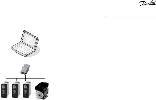
Illustration 1: Connect up to 126 Nodes with a Repeater and up to 31 Nodes without Repeater
1.6 Versions
VLT® Motion Control Tool MCT 10 is available in 2 versions:
•MCT 10 Set-up Software Basic is available free of charge. Download the program from www.danfoss.com - select VLT® Motion Control Tool MCT 10.
•MCT 10 Set-up Software Advanced can be purchased using ordering number 130B1000.
Table 1: Features of the Basic and Advanced Versions
Version supports |
MCT 10 Set-up Software |
MCT 10 Set-up Soft- |
|
Advanced |
ware Basic |
|
|
|
Drives per project |
Unlimited |
4 |
|
|
|
FC protocol |
V |
V |
|
|
|
Functional safety |
V |
|
|
|
|
USB |
V |
V |
|
|
|
PROFIBUS DP-V1 |
V |
V |
|
|
|
PROFIBUS DP-V1 handling multiple Danfoss nodes concurrently |
V(limited performance) |
|
|
|
|
Ethernet-TSC |
V |
V |
|
|
|
Logging and scope function |
8 channels |
2 channels |
|
|
|
Real-time logging from a drive |
4 channels |
|
|
|
|
Alarm display |
V |
View only |
|
|
|
VLT® Motion Control Option MCO 305 |
V |
V |
|
|
|
Graphical smart logic control |
V |
V |
|
|
|
VLT® 5000 to FC 302, VLT® 6000 to FC 102, and VLT® 2800 to FC 280 conver- |
V |
V |
sion wizards |
|
|
|
|
|
|
|
|
12 | Danfoss A/S © 2021.09 |
AQ283728700891en-000201 / 130R0466 |
|

VLT® Motion Control Tool MCT 10 |
|
|
Operating Guide |
|
Introduction |
|
|
|
|
|
|
Version supports |
MCT 10 Set-up Software |
MCT 10 Set-up Soft- |
|
Advanced |
ware Basic |
|
|
|
FC to FC conversion wizard |
V |
V |
|
|
|
Import 3000.XLS to FC 302 |
V |
|
|
|
|
Motor database |
V |
|
|
|
|
VLT® Extended Cascade Controller MCO 101 |
V |
|
|
|
|
Drive file system |
V |
|
|
|
|
VLT® Wireless Control Panel LCP 103 |
V |
V |
|
|
|
Status plug-in |
V |
V |
|
|
|
Drive plug-in |
V |
|
|
|
|
VLT® Software Customizer |
V |
|
|
|
|
1.7 Further Information
The following manuals related to VLT® Motion Control Tool MCT 10 are available:
•VLT® PROFIBUS DP-V1 MCA 101 Installation Guide.
•Design guides for the relevant drives.
Refer to www.danfoss.com/en/about-danfoss/our-businesses/drives/ for more information.
It is also possible to find video training material on this site for operating the MCT 10.
Danfoss A/S © 2021.09 |
AQ283728700891en-000201 / 130R0466 | 13 |

VLT® Motion Control Tool MCT 10
Operating Guide |
Safety |
|
|
2 Safety
2.1 Safety Symbols
The following symbols are used in this manual:
 D A N G E R
Indicates a hazardous situation which, if not avoided, will result in death or serious injury.
 W A R N I N G
Indicates a hazardous situation which, if not avoided, could result in death or serious injury.
 C A U T I O N
Indicates a hazardous situation which, if not avoided, could result in minor or moderate injury.
N O T I C E
Indicates information considered important, but not hazard-related (for example messages relating to property damage).
2.2 Safety Precautions
 W A R N I N G
HIGH VOLTAGE
AC drives contain high voltage when connected to AC mains input , DC supply , or load sharing. Failure to perform installation, start-up, and maintenance by qualified personnel can result in death or serious injury.
-Only qualified personnel must perform installation, start-up, and maintenance.
 W A R N I N G
UNINTENDED START
When the drive is connected to the AC mains, DC supply, or load sharing, the motor may start at any time, causing risk of death, serious injury, and equipment, or property damage. The motor may start by activation of an external switch, a fieldbus command, an input reference signal from the LCP or LOP, via remote operation using MCT 10 Set-up software, or after a cleared fault condition.
-Press [Off] on the LCP before programming parameters.
-Disconnect the drive from the mains whenever personal safety considerations make it necessary to avoid unintended motor start.
-Check that the drive, motor, and any driven equipment is in operational readiness.
14 | Danfoss A/S © 2021.09 |
AQ283728700891en-000201 / 130R0466 |

VLT® Motion Control Tool MCT 10
Operating Guide |
Safety |
|
|
 W A R N I N G
DISCHARGE TIME
The drive contains DC-link capacitors, which can remain charged even when the drive is not powered. High voltage can be present even when the warning indicator lights are off.
Failure to wait the specified time after power has been removed before performing service or repair work could result in death or serious injury.
-Stop the motor.
-Disconnect AC mains, permanent magnet type motors, and remote DC-link supplies, including battery back-ups, UPS, and DC-link connections to other drives.
-Wait for the capacitors to discharge fully before performing any service or repair work. The discharge time is specified in the drive operating guides.
-Use a measuring device to make sure that there is no voltage, before opening the drive or performing any work on the cables.
Danfoss A/S © 2021.09 |
AQ283728700891en-000201 / 130R0466 | 15 |
VLT® Motion Control Tool MCT 10
Operating Guide |
Installation and De-installation |
|
|
3 Installation and De-installation
3.1 Introduction
The VLT® Motion Control Tool MCT 10 Software and SyncPos modules are installed via a multilingual, self-explanatory installation program.
3.1.1 Starting the Installation Program
Procedure
1.Run VLT_MCT10_Vx.xx.msi.
2.Follow the instructions of the installation program.
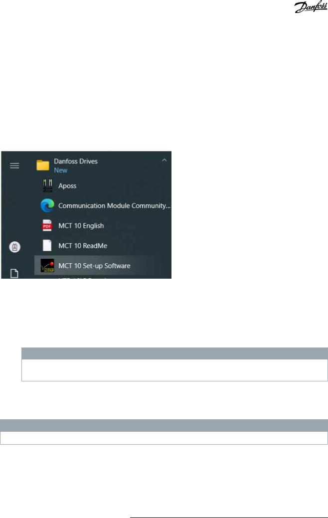
When the installation process is complete, the MCT 10 Set-up Software can be found on the following path:
<![if ! IE]><![endif]>e30bt514.14
Illustration 2: Path for MCT 10 Set-up Software
3.1.2 Selecting the Software Language
The Danfoss default language is English. If another language is selected, it becomes the new default.
Procedure
1.Select Options from the main menu, then select Select Language.
2.Select the wanted language from the scrollbar and click OK.
N O T I C E
Changing the language affects the parameter language. If an external LCP is connected to the drive, the change of language version does not affect the language in the display.
3.Close and restart MCT 10 to activate the language setting.
3.1.3 Uninstalling the Software
N O T I C E
The following procedure is only valid for Windows operating systems.
Procedure
1.Select Start.
2.Select Settings.
3.Select Control Panel.
4.Double-click Remove/Add Programs.
5.Select Remove.
16 | Danfoss A/S © 2021.09 |
AQ283728700891en-000201 / 130R0466 |
VLT® Motion Control Tool MCT 10
Operating Guide |
Set-up of Communication |
|
|
4 Set-up of Communication
4.1 Communication Options
Drives in the VLT® HVAC Drive FC 102, VLT® AQUA Drive FC 202, and VLT® AutomationDrive FC 302 series are equipped with a USB port. Communication from a PC can be established using a standard A–B male-to-male USB cable connected to the drive. No extra hardware or bus configuration is required. If the PC is equipped with more than 1 USB port, several drives can be connected. The USB bus is automatically added to the network bus list.
Establish a hardwired connection through:
•Standard built-in RS485, or
•USB port.
The USB interface socket allows devices to be connected and disconnected using hot swapping. When connecting a drive using USB, MCT 10 Set-up Software automatically adds on to the bus list.
If the VLT® PROFIBUS DP-V1 MCA 101 or the VLT® EtherNet/IP MCA 121 option is mounted in the drive, establish the connection through:
•PROFIBUS master class 2 connection (MSAC 2), or
•Ethernet-based network.
N O T I C E
Connect soft starters either via a USB cable or via ethernet.
N O T I C E
RISK OF DAMAGE TO PC USB HOST CONTROLLER
When connecting the PC to the drive through the USB cable, there is a risk of damaging the PC USB host controller.
-Follow the recommendations for grounding described in the Operating Guide for the relevant drive.
-Use a USB isolator with galvanic isolation to protect the PC USB host controller from ground potential differences when connecting the PC to a drive through a USB cable.
-Do NOT use a PC power cable with a ground plug when the PC is connected to the drive through a USB cable.
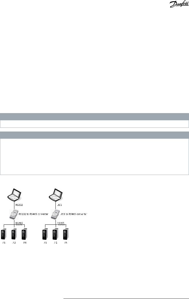
Communication from a PC can be established via RS232 to RS485 converters or via USB to RS485 converters.
<![if ! IE]><![endif]>e30bt631.11
Illustration 3: Communication from a PC
4.2 Manual Fieldbus Configuration
After installation, configure the non-plug-and-play networks via the fieldbus configuration dialog.
Procedure
1.Start the MCT 10 Set-up Software.
2.Select Network.
Danfoss A/S © 2021.09 |
AQ283728700891en-000201 / 130R0466 | 17 |
VLT® Motion Control Tool MCT 10
Operating Guide |
Set-up of Communication |
|
|
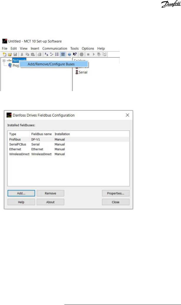
3.Right-click Network and select Add/Remove/Configure Buses.
<![if ! IE]><![endif]>e30bt622.12
Illustration 4: Refreshing the Fieldbus List
4.Add, remove, or configure the properties for the connected buses.
<![if ! IE]><![endif]>e30bt630.13
Illustration 5: Fieldbus Configuration
5.Scan the network for active drives to make MCT 10 indicate available drives on the non-plug-and-play fieldbuses.
4.3Automatic Scan
Only the USB fieldbus is scanned automatically when a drive is connected to the PC. For non-plug-and-play fieldbuses, scan manually for active drives.
4.3.1 Scan Range Configuration
Enter the preferred scan setting by right-clicking SerialCom and then selecting Configure Driver.
Adding a standard bus RS485 or PROFIBUS to the network tree configures the scan range to scan the entire address range. The Ethernet-TSC bus is added using the current IP address settings.
The fieldbus scan range can be configured in several ways:
•Right-click the Fieldbus icon in the network tree and select Configure Bus.
•Mark the Fieldbus icon in the network tree and select Configure under Communication in the main menu bar.
•Open the Fieldbus Configuration dialog, right-click the Network icon, and select Add/Remove/Configure Buses.
•Open from the Windows panel.
18 | Danfoss A/S © 2021.09 |
AQ283728700891en-000201 / 130R0466 |
VLT® Motion Control Tool MCT 10
Operating Guide
Scan network icon
Illustration 6: Scan Network Icon
Set-up of Communication
<![if ! IE]><![endif]>e30bt495.14
4.3.2 Scan Network
Scan a fieldbus in 3 ways:
•Right-click the Fieldbus icon in the network tree and select Scan Bus for active drives.
•Mark the Fieldbus icon in the network tree and select Scan/Refresh under Communication in the main menu bar.
•Mark the Fieldbus icon in the network tree and select the Scan icon on the toolbar.
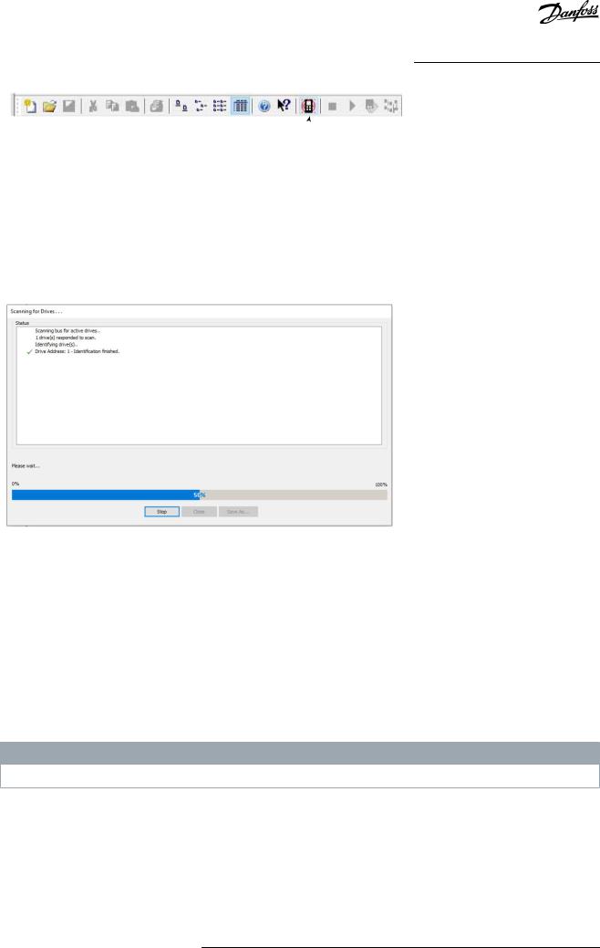
The Scanning for Drives window appears and indicates the progress of the scan.
<![if ! IE]><![endif]>e30bt496.12
Illustration 7: Progress of Network Scanning
4.4 Set Up the Drive with RS485 Data Communication
All drives can be configured to 300, 1200, 4800, 9600 (default), 19200, 38400, 57600, or 115200 baud. The serial configuration is always configured with:
•8 data bits.
•1 stop bit.
•Even parity.
4.4.1 Configuring the Fieldbus
When using an RS485 converter as the Advantech ADAM converter, MCT 10 Set-up Software indicates online drives available on the fieldbus after scanning the bus.
N O T I C E
Protocol and advanced settings are for performance optimization and should normally not be changed.
Procedure
Danfoss A/S © 2021.09 |
AQ283728700891en-000201 / 130R0466 | 19 |
VLT® Motion Control Tool MCT 10
Operating Guide |
Set-up of Communication |
|
|
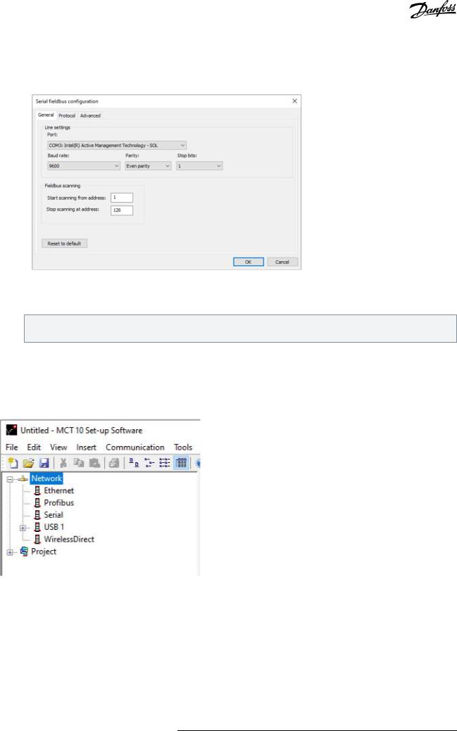
1.Open the Serial Fieldbus Configuration dialog box or right-click the appropriate fieldbus.
<![if ! IE]><![endif]>e30bt629.12
Illustration 8: Serial Fieldbus Configuration
2.Set the COM port number.
When using USB to RS485 converters, the actual COM port number can be identified from the device manager part of the Windows control panel.
3.Set the baud rate, parity, and the number of stop bits (must match the settings in the drive).
4.Set the fieldbus scanning range to the available address to limit the time scanning for active drives.
5.Press OK to activate settings or select to restore the default settings.
4.4.2 USB Data Communication
<![if ! IE]><![endif]>e30bt623.12
Illustration 9: Network Bus List
When the USB cable is disconnected, the drive connected via the USB port is removed from the network bus list.
4.5 Set-up of Soft Starter
Setting up connectivity to the VLT® Soft Starter MCD 500 and VLT® Soft Starter MCD 600 requires that the USB communication module is mounted on the soft starter. Communication from a PC can be established using a standard A–B male-to-male USB cable connected to the USB communication module. If the PC is equipped with more than 1 USB port or a USB HUB, several soft starters can be connected.
20 | Danfoss A/S © 2021.09 |
AQ283728700891en-000201 / 130R0466 |
VLT® Motion Control Tool MCT 10
Operating Guide |
Set-up of Communication |
|
|
4.5.1 Serial Configuration
All soft starters can be configured to 300, 1200, 4800, 9600 (default), 19200, 38400, 57600, or 115200 baud. The serial configuration is always configured with:
•8 data bits.
•1 stop bit.
•No parity.
<![if ! IE]><![endif]>e30bt758.12
Illustration 10: Serial Configuration of Soft Starters
4.5.1.1 Configuring the Fieldbus
Procedure
1.Add and configure the bus from the Fieldbus Configuration dialog.
If the bus is already added to the network, it can be reconfigured by right-clicking on the appropriate soft starter fieldbus.
2.Set the COM port number. The actual COM port number can be identified from the device manager part of the control panel.
3.Set the baud rate, parity, and the number of stop bits (must match the setting in the soft starter).
4.Reset to Default restores the general settings and fieldbus scanning to factory configuration values.
4.5.1.2 Using the Hilscher NetIdent Protocol
Use the tool for searching for devices and for identifying and changing IP addresses. The tool also has a filtering function.
Procedure
1.Click the Tools menu.
Danfoss A/S © 2021.09 |
AQ283728700891en-000201 / 130R0466 | 21 |
VLT® Motion Control Tool MCT 10
Operating Guide |
Set-up of Communication |
|
|
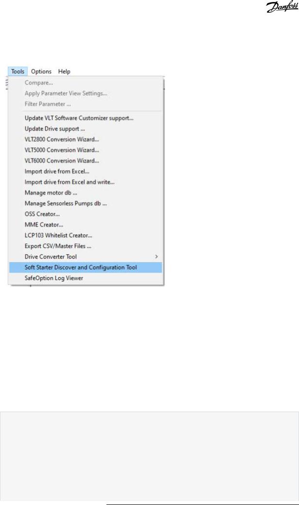
2.Select Soft Starter Discover and Configuration Tool.
<![if ! IE]><![endif]>e30bt980.12
Illustration 11: Selecting the Hilscher NetIdent Tool
3.Select the soft starter for which the IP address should be configured.
4.Click Configure.
4.5.2 Importing/Exporting Parameter Files, MCD 600
With VLT® Soft Starter MCD 600, a parameter file (PAR file) can be exported from the soft starter to a USB stick and copied into VLT® Motion Control Tool MCT 10. After changing the file in MCT 10, the PAR file can be copied back to the USB stick and applied to the soft starter.
Procedure
1.Create an MCD 600 project soft starter.
2.Right-click the project folder.
3.Select Import parameters.
4.From the dialog, select the file to import.
A dialog opens showing information about the selected file.
22 | Danfoss A/S © 2021.09 |
AQ283728700891en-000201 / 130R0466 |
VLT® Motion Control Tool MCT 10 |
|
Operating Guide |
Set-up of Communication |
|
|
|
<![if ! IE]> <![endif]>e30bu310.12 |
If the soft starter differs from the project, it shows up as an error or warning in this view, depending on the difference.
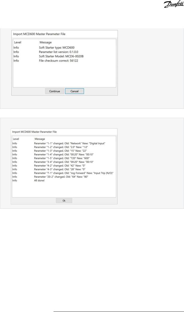
5.Press Continue to apply the file.
A view, which shows all changed parameters, appears.
<![if ! IE]><![endif]>e30bu311.12
6.Click Ok to close the window.
7.Right-click the project to export from MCT 10.
8.Select the parameters to export.
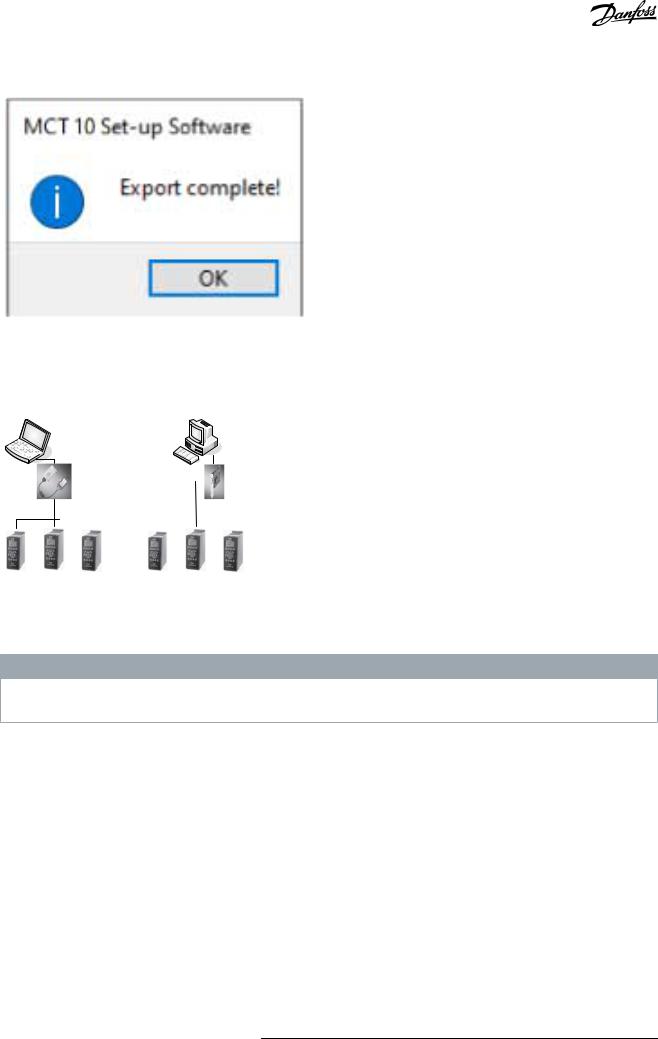
9.In the file selection dialog, select where to export the file to. A dialog appears when the export is completed.
Danfoss A/S © 2021.09 |
AQ283728700891en-000201 / 130R0466 | 23 |
VLT® Motion Control Tool MCT 10 |
|
Operating Guide |
Set-up of Communication |
|
|
|
<![if ! IE]> <![endif]>e30bu312.11 |
4.6 PROFIBUS DP-V1 Communication
Setting up PROFIBUS DP-V1 communication requires a VLT® PROFIBUS DP-V1 MCA 101 option module. Communication from a PC using PROFIBUS DP-V1 can be established using a PROFIBUS PCMCIA card or a card installed in the PC. The PROFIBUS cable from the drive is connected to the 9-pin sub D socket connector on the card.
<![if ! IE]><![endif]>e30bt634.11
PCMCIA |
|
|
|
Insertable |
||||
DP-V1 card |
|
|
|
DP-V1 card |
||||
DP-V1 |
|
DP-V1 |
||||||
|
|
|
|
|
|
|
|
|
#1 |
#2 |
#N |
#1 |
#2 |
#N |
Illustration 12: PROFIBS DP-V1 Communication
Consult Siemens www.siemens.com for the latest supported cards for PCs.
N O T I C E
Connectivity via PROFIBUS DP-V1 to a VLT® AutomationDrive FC 302 utilizing the VLT® PROFIBUS Converter MCA 114 with option firmware version 2.03 is not possible from MCT 10 Set-up Software. Use the fieldbus or USB bus instead.
4.6.1 Configuring PROFIBUS DP-V1
When using a PROFIBUS interface card with the associated driver installed, MCT 10 Set-up Software indicates online drives available on the specific PROFIBUS after scanning the bus for active drives.
Procedure
24 | Danfoss A/S © 2021.09 |
AQ283728700891en-000201 / 130R0466 |
VLT® Motion Control Tool MCT 10
Operating Guide |
Set-up of Communication |
|
|
1.Configure the bus from the Fieldbus Configuration dialog or by right-clicking the appropriate PROFIBUS bus.
<![if ! IE]><![endif]>e30bt625.14
Illustration 13: PROFIBUS Fieldbus Configuration
2.Set the board number.
3.Set the fieldbus scanning range to the available addresses only to limit the time used for scanning active drives.
4.Press OK to activate or reset to restore factory default settings.
4.6.2 DP-V1 Connection and PG/PC Interface
The MCT 10 Set-up Software PROFIBUS DP-V1 fieldbus plug-in utilizes the Siemens SoftNet driver available from Step7, or alternatively Simatic NET, to establish connectivity via the supported master class 2 cards such as CP5511 or CP5512.
N O T I C E
STEP7 Lite version does not support the SoftNet driver.
4.6.2.1 Setting Up the PG/PC Interface
This procedure explains how to set up the PG/PC Interface from default configuration to open the PROFIBUS connection from MCT 10.
Cabling and terminations must be in accordance with wiring and cabling requirements for PROFIBUS.
Procedure
Danfoss A/S © 2021.09 |
AQ283728700891en-000201 / 130R0466 | 25 |
VLT® Motion Control Tool MCT 10
Operating Guide |
Set-up of Communication |
|
|
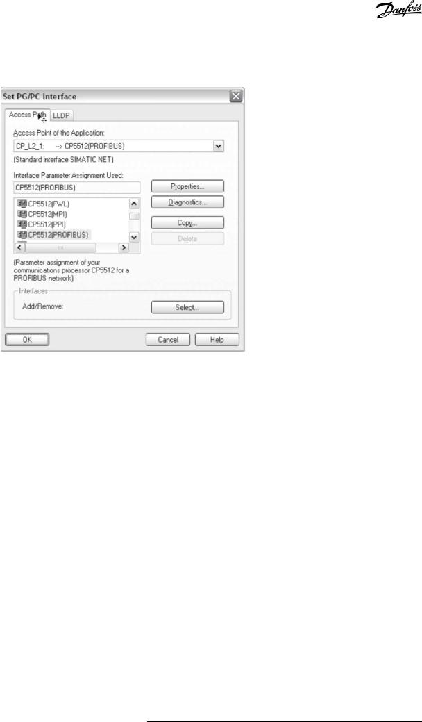
1.Open the PG/PC Interface.
<![if ! IE]><![endif]>e30bt789.10
Illustration 14: Set PG/PC Interface
2.Configure Access Point of the Application to CP_L2_1 pointing to the master class 2 card used.
3.Set Interface Parameter Assignment Used corresponding to the master class 2 card used.
4.Select Properties to configure the stationand network parameters. - Station parameters:
Set PG/PC is the only master on the bus to Active if no PLC is active on the bus. Use the Diagnostics described later to select a valid PROFIBUS address.
-Network parameters:
Set the Transmission rate to the same baud rate as the PLC if it is active.
5.Use DP as Profile and click OK to close the Properties dialog.
26 | Danfoss A/S © 2021.09 |
AQ283728700891en-000201 / 130R0466 |
VLT® Motion Control Tool MCT 10
Operating Guide |
Set-up of Communication |
|
|
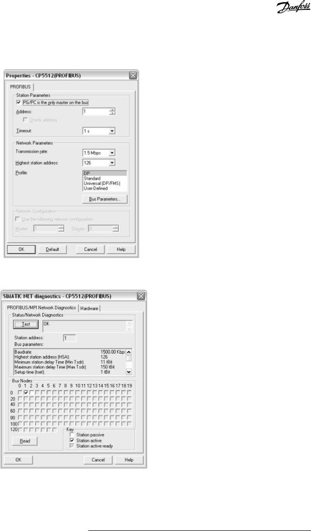
6.Select Diagnostics in the Set PG/PC Interface to verify networkand bus communication.
<![if ! IE]><![endif]>e30bt790.11
Illustration 15: Properties Dialog
<![if ! IE]><![endif]>130BT791.10
Illustration 16: Simatic Network Diagnostics Dialog
7.Select Test to verify the access path and network configuration. If a sharing violation is detected, the test results in an error message. When the test result is successful, select Read to identify the active PROFIBUS nodes available on the network. Make sure that the address defined for the PG/PC interface does not conflict with an active node.
Danfoss A/S © 2021.09 |
AQ283728700891en-000201 / 130R0466 | 27 |

VLT® Motion Control Tool MCT 10
Operating Guide |
Set-up of Communication |
|
|
8.Close the PG/PC interface and start MCT 10.
9.Right-click a PROFIBUS and select Scan for active drives. MCT 10 Set-up Software identifies the same node IDs, except PLCs.
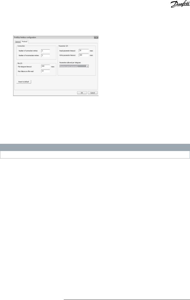
4.6.3 PROFIBUS Multitelegrams
With the Parameters allowed per telegram drop-down list, it is possible to configure the number of requests to be associated within a multitelegram. The standard allows up to 40 telegrams to be associated.
The following options are available:
•Maximum speed (default configuration). Handles the association automatically and adapts the number of telegrams for each drive according to the series. Can be used in PROFIBUS networks containing both old and new Danfoss drives.
•Conservative. Always associates 10 telegrams within a multitelegram. This option is useful when communicating only with old products such as the VLT® Decentral Drives FCD 300, VLT® DriveMotor FCM 300, series derived from VLT® HVAC Drive FC 102, VLT® AQUA Drive FC 202, and VLT® AutomationDrive FC 302.
•Single request. Only 1 request per telegram.
4.7 Ethernet-TSC Data Communication
To set up an Ethernet-TSC (transparent socket channel) communication, the VLT® EtherNet/IP MCA 121 option module is required within the drive. Communication from a PC can be established using a standard Ethernet cable connected to the drive.
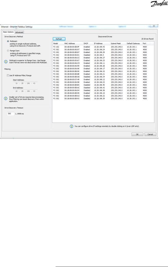
4.7.1 Ethernet-TSC Configuration
An Ethernet-TSC bus is scanned using DDP (drive discovery protocol). The protocol does not require an IP port number and IP scan range. It identifies drives based on the MAC addresses.
N O T I C E
When scanning through different subnets or remotely via a VPN tunnel, it is advised not to utilize the ADDP protocol but to use an IP range.
Click Refresh to generate a list of all active drives in the Ethernet. The list appears in the Ethernet Fieldbus Settings dialog when the scan is complete.
28 | Danfoss A/S © 2021.09 |
AQ283728700891en-000201 / 130R0466 |
VLT® Motion Control Tool MCT 10 |
|
Operating Guide |
Set-up of Communication |
|
|
|
<![if ! IE]> <![endif]>e30bt775.13 |
Illustration 17: ADDP Configuration
Drive types without any IP configuration use their Auto IP Class B address, which is 169.254.yy.xx, with yy.xx corresponding to the last 2 segments in the MAC address. Several uncommissioned drives without any IP configuration can be scanned on the same network.
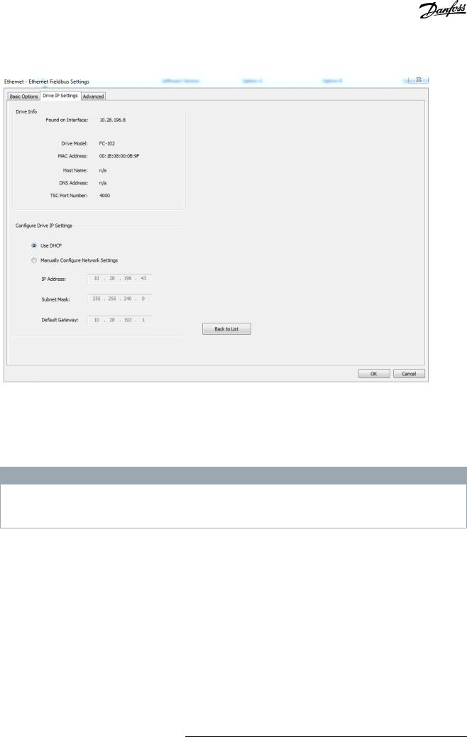
Select a device from the Discovered Drives list to;
•Get more information about the device.
•Assign a static IP address, a subnet mask, or default value to the drive.
•Set up DHCP (dynamic host configuration protocol) look-up.
Danfoss A/S © 2021.09 |
AQ283728700891en-000201 / 130R0466 | 29 |
VLT® Motion Control Tool MCT 10 |
|
Operating Guide |
Set-up of Communication |
|
|
|
<![if ! IE]> <![endif]>e30bt857.11 |
Illustration 18: TSC Configure
4.7.1.1 Scanning with IP Range
When scanning using an IP range, the Ethernet telegrams are transmitted as traditional TCP/IP packages routed out in a router, switch, or manage switch without requiring any changes. The disadvantage is an increased scanning time, and drives without IP address configured are not identified.
N O T I C E
Identification of drives using the VLT® EtherNet/IP MCA 121 option is possible only from option firmware version 1.03 or newer. If using options with firmware versions earlier than 1.03, configure parameter 12-89 Transparent Socket Channel Power to 0 to prevent the option from failing to operate.
Procedure
30 | Danfoss A/S © 2021.09 |
AQ283728700891en-000201 / 130R0466 |
Loading...