


Data Sheet
Evaporator pressure regulator
Type KVP
Maintains a constant evaporating pressure
The KVP is mounted in the suction line after the evaporator and is used to:
1. Maintain a constant evaporating pressure and thereby a constant surface temperature on the evaporator. The regulation is modulating. By throttling in the suction line, the amount of refrigerant gas is matched to the evaporator load.
2. Protect against an evaporating pressure that is too low (e.g. as protection against freezing in a water chiller). The regulator closes when the pressure in the evaporator falls below the set value.
3. Di€erentiate between the evaporating pressures in two or more evaporators in systems with one compressor.
Features
• Accurate, adjustable pressure regulation
• Wide capacity and operating range
• Pulsation damping design
• Stainless steel bellows
• Compact angle design for easy installation in any position
• “Hermetic” brazed construction
• 1⁄4 in. Schrader valve for pressure testing
• Available with …are and ODF solder connections
• KVP 12 – KVL 22: may be used in the following EX range: Category 3 (Zone 2)
AI249086497299en-001001

Evaporator pressure regulator, type KVP
Functions
Figure 1: Design/Function for KVP
|
1 |
= 8 mm |
|
2 |
|
|
|
|
|
3 |
|
|
4 |
|
|
5 |
|
|
6 |
|
|
7 |
|
|
8 |
|
10 |
9 |
|
|
|
|
11 |
|
|
12 |
|
|
13 |
|
|
1 |
Protective cap |
|
|
2 |
Gasket |
|
|
3 |
Setting screw |
|
|
4 |
Main spring |
|
|
5 |
Valve body |
|
|
6 |
Equalization bellows |
|
|
7 |
Valve plate |
|
|
8 |
Valve seat |
|
|
9 |
Damping device |
|
|
10 |
Pressure gauge connection |
|
|
11 |
Cap |
|
|
12 |
Gasket |
|
|
13 |
Insert |
|
|
The evaporator pressure regulator, type KVP opens on a rise in pressure on the inlet side, i.e. when the pressure in the evaporator exceeds the set value.
Type KVP regulates inlet pressure only. Pressure variations on the outlet side of the regulator do not a€ect the degree of opening as the valve is equipped with equalization bellows (6).
The bellows have an e€ective area corresponding to that of the valve seat neutralising any a€ect to the setting.
The KVP is also equipped with a damping device (9) providing protection against pulsations which can normally arise in a refrigeration system.
The damping device helps to ensure long life for the regulator without impairing regulation accuracy.
© Danfoss | Climate Solutions | 2021.08 |
AI249086497299en-001001 | 2 |
Evaporator pressure regulator, type KVP
Figure 2: P-band and Offset
C |
<![if ! IE]> <![endif]>Danfoss 34L181.10 |
|
|
|
S |
|
B |
|
O |
|
P |
Proportional band
C Capacity
B bar
S Setting
Oo€set
PP- band
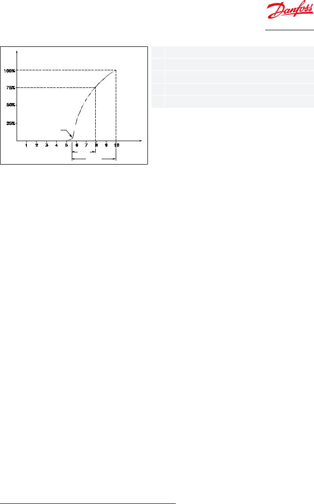
The proportional band or P-band is deˆned as the amount of pressure required to move the valve plate from a closed to a fully open position
Example
If the valve is set to open at 4 bar and the valve P-band is 1.7, the valve will provide maximum capacity when the inlet pressure reaches 5.7 bar.
O€set
The o€set is deˆned as the permissible pressure variation in evaporator pressure (temperature). It is calculated as the di€erence between the required working pressure and the minimum allowable pressure.
The o€set is always a part of the P-band.
Example with R22
A working temperature of 5 °C ~ 4.9 bar is required, and the temperature must not drop below 0.5 °C ~ 4.1 bar. The o€set will then be 0.8 bar.
When selecting a valve, be sure to correct the evaporator capacity based on the required o€set.
© Danfoss | Climate Solutions | 2021.08 |
AI249086497299en-001001 | 3 |

Evaporator pressure regulator, type KVP
Product specification
Technical data
Table 1: Technical data for KVP
Features |
|
Description |
||
|
|
|
R22, R134a, R290(1), R404A, R407A, R407C, R407F, R407H, R448A, R449A, R449B, |
|
Refrigerants |
R450A, R452A, R454A(1), R454C(1), R455A(1), R507, R513A, R515B, R516A, R600(1), |
|||
|
|
|
R600a(1), R1234ze(E)(1), R1234yf(1), R1270(1) |
|
Regulating range |
0 – 5.5 bar |
|||
Factory setting = 2 bar |
||||
|
|
|
||
|
|
|||
Max. working pressure |
PS/MWP PS = 18 bar |
|||
Max. test pressure |
Pe = PS × 1.1 = 19.8 bar |
|||
Medium temperature range |
-45 – 130 °C |
|||
|
|
|
|
|
Maximum P-band |
KVP 12 – 22: 1.7 bar |
|||
KVP 28 – 35: 2.8 bar |
||||
|
|
|
||
K |
-value(2) |
with o€set 0.6 bar |
KVP 12 – 22: 1.7 m3 / h |
|
|
||||
v |
|
|
KVP 28 – 35: 2.8 m3 / h |
|
|
|
|
||
K |
-value(2) |
with maximum P-band |
KVP 12 – 22: 2.5 m3 / h |
|
|
||||
v |
|
|
KVP 28 – 35: 8.0 m3 / h |
|
|
|
|
||
(1)KVP 12 – KVP 22 only
(2)The Kv value is the …ow of water in [m3 / h] at a pressure drop across valve of 1 bar, ρ = 1000 kg / m3.
This product (KVP 12 – KVP 22) is evaluated for R290, R454A, R454C, R455A, R600, R600a, R1234ze(E), R1234yf, R2170 by ignition source assessment in accordance with standard EN ISO80079-36. Flare connections are only approved for A1 and A2L refrigerants.
For complete list of approved refrigerants, visit store.danfoss.com and search for individual code numbers, where refrigerants are listed as part of technical data.
Sizing
For optimum performance, it is important to select a KVP valve according to system conditions and applications.
The following data must be used when sizing a KVP valve:
•Refrigerant
•Evaporator capacity: Qe in [kW]
•Evaporating temperature (required temperature): te in [°C]
•Minimum evaporating temperature: te in [°C]
•Liquid temperature ahead of expansion valve: tl in [°C]
•Connection type: …are or solder
•Connection size in [in.]
Capacity tables
Table 2: Regulator capacity Q |
1) [kW] with offset = 0.6 bar, R134a |
|
|
|
|
|||||
|
|
e |
|
|
|
|
|
|
|
|
|
Pressure drop |
|
|
|
Evaporating temperature te |
|
|
|
||
|
in regulator |
|
|
|
|
|
|
|||
Type |
|
|
|
|
[°C] |
|
|
|
||
∆p |
|
|
|
|
|
|
|
|||
|
|
|
|
|
|
|
|
|
||
|
[bar] |
-15 |
-10 |
-5 |
0 |
5 |
10 |
15 |
20 |
|
|
0.1 |
2 |
2.3 |
2.6 |
2.9 |
3.2 |
3.6 |
4 |
4.4 |
|
|
0.2 |
2.8 |
3.1 |
3.6 |
4 |
4.5 |
5 |
5.5 |
6.1 |
|
KVP 12 |
0.3 |
3.2 |
3.7 |
4.2 |
4.8 |
5.4 |
6 |
6.7 |
7.4 |
|
KVP 15 |
||||||||||
0.4 |
3.6 |
4.1 |
4.8 |
5.4 |
6.1 |
6.8 |
7.6 |
8.4 |
||
KVP 22 |
||||||||||
|
|
|
|
|
|
|
|
|
||
|
0.5 |
3.8 |
4.4 |
5.1 |
5.9 |
6.7 |
7.5 |
8.4 |
9.3 |
|
|
0.6 |
3.9 |
4.7 |
5.5 |
6.3 |
7.1 |
8.1 |
9 |
10 |
|
|
|
|
|
|
|
|
|
|
|
|
© Danfoss | Climate Solutions | 2021.08 |
AI249086497299en-001001 | 4 |
 Loading...