


Danfoss PAHT 2, PAHT 3.2, PAHT 4, PAHT 6.3, PAHT 10 Operating guide
...Operation guide
PAHT pumps
PAHT 2/3.2/4/6.3/10 and 12.5 Operation, Installation and Maintenance Manual
hpp.danfoss.com

Operation guide | Installation, Operation and Maintenance Manual for PAHT 2-12.5 pumps
Table of Contents |
Contents |
|
|
|
|
|
|
|
|
Table of Contents . . . . . . . . . . . . . . . . . . . . . . . . . . . . . . . . . . . . . . . . . . . . . . . . . . . |
. . . . . . . . . . . . . . . . . . . . 2 |
|
|
|
|
Validity . . . . . . . . . . . . . . . . . . . . . . . . . . . . . . . . . . . . . . . . . . . . . . . . . |
. . . . . . . . . . . . . . . . 4. . . . . . . . . . . . . |
|
1. |
|
|
Introduction . . . . . . . . . . . . . . . . . . . . . . . . . . . . . . . . . . . . . . . . . . . . . . . . . . . . |
. . . . . . . . . . . . . . . . . .6. . . . . . |
|
1.1 |
|
. |
General . . . . . . . . . . . . . . . . . . . . . . . . . . . . . . . . . . . . . . . . . . . . . . . . . . . . . . . . . . . . . . |
. . . . . . . . . . . . . . . . . . . 6 |
|
1. 2 |
|
. |
Symbols . . . . . . . . . . . . . . . . . . . . . . . . . . . . . . . . . . . . . . . . . . . . . . . . . . . . . . . . . . . . . |
. . . . . . . . . . . . . . . . . . . 6 |
|
1..3 |
|
|
Manufacturer and customer service address:. . . . . . . . . . . . . . . . . . . . . . . . . . |
. . . . . . . . . . . . . . . . . . . 7 |
|
1..4 |
|
|
Country specific information . . . . . . . . . . . . . . . . . . . . . . . . . . . . . . . . . . |
. . . . . . . . . . . . . . . . .7. . . . . . . . . |
|
1. 4. 1 |
|
|
United Kingdom . . . . . . . . . . . . . . . . . . . . . . . . . . . . . . . . . . . . . . . . . . . . . |
. . . . . . . . . . . . . . . . .7. . . . . . . . . . |
|
2. |
|
|
. Safety. . . . . . . . . . . . . . . . . . . . . . . . . . . . . . . . . . . . . . . . . . |
. . . . . . . . . . . . . 7. . . . . . . . . . . |
|
2..1 |
|
|
General information. . . . . . . . . . . . . . . . . . . . . . . . . . . . . . . . . . . . . . . . . . . . . . . . . . |
. . . . . . . . . . . . . . . . . . . 7 |
|
2..2 |
|
|
Preferred system design . . . . . . . . . . . . . . . . . . . . . . . . . . . . . . . . . . . . . . . . . . . . . . |
. . . . . . . . . . . . . . . . . . . 7 |
|
2..3 |
|
|
Commissioning and servicing the unit . . . . . . . . . . . . . . . . . . . . . . . . . . . . . . . . |
. . . . . . . . . . . . . . . . . . . 8 |
|
2..4 |
|
|
Adhere to the following important points . . . . . . . . . . . . . . . . . . . . |
. . . . . . . . . . . . . . 8. . . . . . . . . . . . |
|
2..5 |
|
|
In case of doubt . . . . . . . . . . . . . . . . . . . . . . . . . . . . . . . . . . . . . . . . . . . . . . . . . . . . . . |
. . . . . . . . . . . . . . . . . . . 8 |
|
3. |
|
|
Technical data . . . . . . . . . . . . . . . . . . . . . . . . . . . . . . . . . . . . . . . . . . . . . . . . . . . . . . . |
. . . . . . . . . . . . . . . . . . . 8 |
|
3..1 |
|
|
Approved applications and operational limits for the pumps . . . . . . . . . . |
. . . . . . . . . . . . . . . . . . . 8 |
|
3..2 |
|
|
Application range . . . . . . . . . . . . . . . . . . . . . . . . . . . . . . . . . . . . . . . . . . . . . . . . . . . . |
. . . . . . . . . . . . . . . . . . . 8 |
|
3..3 |
|
|
Electric motor data . . . . . . . . . . . . . . . . . . . . . . . . . . . . . . . . . . . . . . . . . . . . . . . . . . . |
. . . . . . . . . . . . . . . . . . . 8 |
|
3..4 |
|
|
Noise and vibration . . . . . . . . . . . . . . . . . . . . . . . . . . . . . . . . . . . . . . . . . . |
. . . . . . . . . . . . . . . . .8. . . . . . . . . . |
|
3..5 |
|
|
Dimension drawings . . . . . . . . . . . . . . . . . . . . . . . . . . . . . . . . . . . . . . . . . . . . |
. . . . . . . . . . . . . . . . . .8. . . . . . |
|
3..6 |
|
|
Space requirement . . . . . . . . . . . . . . . . . . . . . . . . . . . . . . . . . . . . . . . . . . . . . . . . . . . |
. . . . . . . . . . . . . . . . . . . 8 |
|
3.7 |
|
. |
Filtration . . . . . . . . . . . . . . . . . . . . . . . . . . . . . . . . . . . . . . . . . . . . . . . . . . . . . . . . . . . . . |
. . . . . . . . . . . . . . . . . . . 9 |
|
3..8 |
|
|
Properties of water . . . . . . . . . . . . . . . . . . . . . . . . . . . . . . . . . . . . . . . . . . . . . . . . . . . |
. . . . . . . . . . . . . . . . . . . 9 |
|
3..9 |
|
|
Air bubbles . . . . . . . . . . . . . . . . . . . . . . . . . . . . . . . . . . . . . . . . . . . . . . . |
. . . . . . . . . . . . . . . .9. . . . . . . . . . . . . |
|
3.10 |
. |
|
Chemicals. . . . . . . . . . . . . . . . . . . . . . . . . . . . . . . . . . . . . . . . . . . . . . . . . . . . . . . . . . . . |
. . . . . . . . . . . . . . . . . . . 9 |
|
4. |
|
|
Arrival inspection, transportation, handling, lifting and storage . . . . . . |
. . . . . . . . . . . . . . . . 9. . . . |
|
4..1 |
|
|
Arrival inspection . . . . . . . . . . . . . . . . . . . . . . . . . . . . . . . . . . . . . . . . . . . . . . |
. . . . . . . . . . . . . . . . . .9. . . . . . . |
|
4. 2 |
|
. |
Warning . . . . . . . . . . . . . . . . . . . . . . . . . . . . . . . . . . . . . . . . . . . . . . . . . . |
. . . . . . . . . . . . . . . 9. . . . . . . . . . . . . |
|
4..3 |
|
|
General safety information . . . . . . . . . . . . . . . . . . . . . . . . . . . . . . . . . . . . . . . . . . . |
. . . . . . . . . . . . . . . . . . . 9 |
|
4..4 |
|
|
Transport and handling . . . . . . . . . . . . . . . . . . . . . . . . . . . . . . . . . . . . |
. . . . . . . . . . . . . . . .9. . . . . . . . . . . . . |
|
4..5 |
|
|
Return to supplier . . . . . . . . . . . . . . . . . . . . . . . . . . . . . . . . . . . . . . . . . . . . . . . . . . . . |
. . . . . . . . . . . . . . . . . . 10 |
|
4. 6 |
|
. |
Storage . . . . . . . . . . . . . . . . . . . . . . . . . . . . . . . . . . . . . . . . . . . . . . . . . . . . . . . . . . . . . . |
. . . . . . . . . . . . . . . . . . 10 |
|
5. |
|
|
Installation and commissioning. . . . . . . . . . . . . . . . . . . . . . . . . . . . . . . . . . . . . . . |
. . . . . . . . . . . . . . . . . . 11 |
|
5..1 |
|
|
Important dimensions . . . . . . . . . . . . . . . . . . . . . . . . . . . . . . . . |
. . . . . . . . . . . . . 11. . . . . . . . . . . . |
|
5. 2 |
|
. |
Cleanliness . . . . . . . . . . . . . . . . . . . . . . . . . . . . . . . . . . . . . . . . . . . . . . . . . . . . . . . . . . . |
. . . . . . . . . . . . . . . . . . 11 |
|
5..3 |
|
|
Fluid temperature . . . . . . . . . . . . . . . . . . . . . . . . . . . . . . . . . . . . . . . . . . . . . . . . . . . . |
. . . . . . . . . . . . . . . . . . 11 |
|
5..4 |
|
|
Electrical data . . . . . . . . . . . . . . . . . . . . . . . . . . . . . . . . . . . . . . . . . . . . . . . . . . . . . . . . |
. . . . . . . . . . . . . . . . . . 11 |
|
5..5 |
|
|
Local regulations . . . . . . . . . . . . . . . . . . . . . . . . . . . . . . . . . . . . . . . . . . . . . . . . . . . . . |
. . . . . . . . . . . . . . . . . . 11 |
|
5..6 |
|
|
Pre mounting checklist, based on Danfoss preferred system designs . |
. . . . . . . . . . . . . . 12. . . . . |
|
5..7 |
|
|
Lifting and positioning . . . . . . . . . . . . . . . . . . . . . . . . . . . . . . . . . . . . . . . . . . . . . . . |
. . . . . . . . . . . . . . . . . . 12 |
|
5..8 |
|
|
Mount the different equipment . . . . . . . . . . . . . . . . . . . . . . . . . . . . . . . . . . . . . . |
. . . . . . . . . . . . . . . . . . 12 |
|
5. |
|
.9 Electrics . . . . . . . . . . . . . . . . . . . . . . . . . . . . . . . . . . . . . . . . . . . |
. . . . . . . . . . . . .12. . . . . . . . . . . . |
|
|
5.10 |
. |
|
Instrumentation . . . . . . . . . . . . . . . . . . . . . . . . . . . . . . . . . . . . . |
. . . . . . . . . . . . .12. . . . . . . . . . . . |
|
5.11 |
. |
|
Connections . . . . . . . . . . . . . . . . . . . . . . . . . . . . . . . . . . . . . . . . . . . . . . . . . . . . . . |
. . . . . . . . . . . . . . . . .12. . . . |
|
5..12 |
|
|
Ensure free flow . . . . . . . . . . . . . . . . . . . . . . . . . . . . . . . . . . . . . . . . . . . |
. . . . . . . . . . . . . . .13. . . . . . . . . . . . . |
|
5..13 |
|
|
Verify setting of safety/relief valves . . . . . . . . . . . . . . . . . . . . . . . . . . . . . . . . . . . |
. . . . . . . . . . . . . . . . . . 13 |
|
5..14 |
|
|
Bleed and remove air from the pump . . . . . . . . . . . . . . . . . . . . . . . . . . . . . . . . . |
. . . . . . . . . . . . . . . . . . 13 |
|
5..15 |
|
|
Verify direction of rotation . . . . . . . . . . . . . . . . . . . . . . . . . . . . . . . . . |
. . . . . . . . . . . . . .13. . . . . . . . . . . . . |
|
5.16 |
. |
|
Commissioning . . . . . . . . . . . . . . . . . . . . . . . . . . . . . . . . . . . . . . . . . . . . . . . |
. . . . . . . . . . . . . . . . 13. . . . . . . . . |
|
5..16..1 |
|
|
Open system . . . . . . . . . . . . . . . . . . . . . . . . . . . . . . . . . . . . . . . . . . . . . . . . . . . . . . . . . |
. . . . . . . . . . . . . . . . . . 13 |
|
5. 16. 2 |
|
|
Closed system (not applicable for PAHT G 256-308) . . . . . . . . |
. . . . . . . . . 13 |
|
5..17 |
|
|
Check the filter condition . . . . . . . . . . . . . . . . . . . . . . . . . . . . . . . . . . . . . . . . . . . . . |
. . . . . . . . . . . . . . . . . . 13 |
|
5..18 |
|
|
Instruct operator and maintenance personnel . . . . . . . . . . . . . . . . . . . . . . . . |
. . . . . . . . . . . . . . . . . . 13 |
|
6. |
|
|
Operation of motor pump unit . . . . . . . . . . . . . . . . . . . . . . . . . . . . . . . . |
. . . . . . . . . . . . . . . .14. . . . . . . . |
|
6..1 |
|
|
General safety information . . . . . . . . . . . . . . . . . . . . . . . . . . . . . . . . . . . . . . . . . . . |
. . . . . . . . . . . . . . . . . . 14 |
|
6..2 |
|
|
What to listen and look for |
14 |
|
|
|
|
||
2 |
180R9287 |AQ073186503097en-001001 | IOM PAHT 2-12.5 pumps | 01.2022 |
|

Operation guide | Installation, Operation and Maintenance Manual for PAHT 2-12.5 pumps
7. |
Maintenance and service of the pump unit . . . . . . . . . . . . . . . . . . . . . . . . . . . . . . . . |
14. . . . . . . |
7..1 |
General safety information . . . . . . . . . . . . . . . . . . . . . . . . . . . . . . . . . . . . . . . . . . . . . . . . . . . . . . . . . . . . . |
14 |
7..2 |
Service and inspection interval for the pump . . . . . . . . . . . . . . . . . . . . . . . . . . . . . . . . . . . |
.14. . . . . . . |
7..3 |
Shut down of the system . . . . . . . . . . . . . . . . . . . . . . . . . . . . . . . . . . . . . . . . . . . . . . . . . . . . . . . . . . . . . . . |
14 |
7..4 |
Disassembling and assembling the pump unit . . . . . . . . . . . . . . . . . . . . . . . . . . . . . . . . . . . . . . . . . . |
15 |
7..5 |
Assembling the pump unit . . . . . . . . . . . . . . . . . . . . . . . . . . . . . . . . . . . . . . . . . . . . . . . . . . . . . . . . . . . |
15. . |
7..6 |
Procedure for mounting the pump back onto electric motor . . . . . . . . . . . . . . . . . . . . . . . . |
.15. . . |
7..7 |
Getting the pump unit back into operation . . . . . . . . . . . . . . . . . . . . . . . . . . . . . . . . . . . . . . . . . . . . . |
15 |
7..8 |
Storage of the pump . . . . . . . . . . . . . . . . . . . . . . . . . . . . . . . . . . . . . . . . . . . . . . . . . . . . . . . . . . . . . . . . |
15. . . |
8. |
Troubleshooting and scrapping criteria . . . . . . . . . . . . . . . . . . . . . . . . . . . . . . . . . . . . |
16. . . . . . . |
8..1 |
General safety information . . . . . . . . . . . . . . . . . . . . . . . . . . . . . . . . . . . . . . . . . . . . . . . . . . . . . . . . . . . . . |
16 |
8..2 |
Operational conditions which can cause pump failures. . . . . . . . . . . . . . . . . . . . . . . . . . . . . . . . . . |
16 |
8..3 |
Mechanical failure. . . . . . . . . . . . . . . . . . . . . . . . . . . . . . . . . . . . . . . . . . . . . . . . . . . . . . . . . . . . . . . . . . . . . . |
16 |
8..4 |
Electrical failure . . . . . . . . . . . . . . . . . . . . . . . . . . . . . . . . . . . . . . . . . . . . . . . . . . . . . . . . . . . . . . . . . . . . . . . . |
16 |
8. 5 |
. Responsibility . . . . . . . . . . . . . . . . . . . . . . . . . . . . . . . . . . . . . . . . . . . . . . . . . . . . . . . . . . . . . . . . . . . . . . . . . . |
16 |
8..6 |
Scrapping criteria . . . . . . . . . . . . . . . . . . . . . . . . . . . . . . . . . . . . . . . . . . . . . . . . . . . . . . . . . . . . . . . . . |
16. . . . . |
Appendices
Table of Contents . . . . . . . . . . . . . . . . . . . . . . . . . . . . . . . . . . . . . . . . . . . . . . . . . . . . . . . . . . . . . . . . . . . . . . . . . . . . . . 18. . .
1. Data sheet PAHT 2-308 pumps (AI106586503085en-000901) .. .. .. .. .. .. .. .. .. .. .. .. .. .. .. .. .. .. .. .. .. .. .. .. .. .. .. ..19 2. Pump instruction PAHT 2-12..5 (180R9277) . . . . . . . . . . . . . . . . . . . . . . . . . . . . . . . . . . . . . . . . . . . . . . .33
3. Electric motor manual (180R9230) . . . . . . . . . . . . . . . . . . . . . . . . . . . . . . . . . . . . . . . . . . . . . . .43. . . . . . .
4. Parts list PAHT (AX322445815902en-000201) . . . . . . . . . . . . . . . . . . . . . . . . . . . . . . . . . . . . . . . . . . . .49 5. Trouble shooting guide for PAH, PAHT, PAHT G, PAHT 674 and PAH F pumps . . . . . . . . . . . . 59. 6. Right and wrong - Trouble shooting guide for water hydraulic systems (180R9042) . . . . . . .71
180R9287 |AQ073186503097en-001001 | IOM PAHT 2-12.5 pumps | 01.2022 |
3 |

Operation guide | Installation, Operation and Maintenance Manual for PAHT 2-12.5 pumps
Validity |
This manual is valid for PAHT pumps with the following code numbers/serial numbers: |
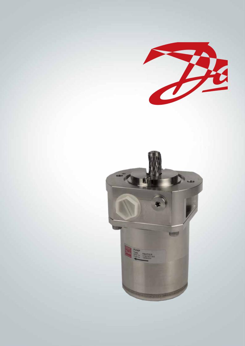
PAHT 2.0 |
Code no.. |
180B0031 |
|
|
|
|
Serial no.. |
XXXXXX08-XXX |
|
|
|
PAHT 3.2 |
Code no.. |
180B0077 |
|
|
|
|
Serial no.. |
XXXXXX03-XXX |
|
|
|
PAHT 4.0 |
Code no.. |
180B0030 |
|
|
|
|
Serial no.. |
XXXXXX08-XXX |
|
|
|
PAHT 6.3 |
Code no.. |
180B0029 |
|
|
|
|
Serial no.. |
XXXXXX08-XXX |
|
|
|
PAHT 10 |
Code no.. |
180B0032 |
|
|
|
|
Serial no.. |
XXXXXX07-XXX |
|
|
|
PAHT 12.5 |
Code no.. |
180B0033 |
|
|
|
|
Serial no.. |
XXXXXX07-XXX |
|
|
|
T
Serial 
The serial number is referring to the Serial no.. on the product label.. The digits shown (07) indicate the version number of the pump..
This documentation is compatible with previous pump versions..
4 |
180R9287 |AQ073186503097en-001001 | IOM PAHT 2-12.5 pumps | 01.2022 |
|
Operation guide | Installation, Operation and Maintenance Manual for PAHT 2-12.5 pumps
1. Introduction |
1.1 General |
|
The PAHT pumps and pump units are manufac- |
|
tured by Danfoss A/S, and are sold and marketed |
|
by a net of authorized distributors world wide.. |
|
This manual contains the necessary instructions |
|
for the installation, operation and service of the |
|
pumps used for technical water.. |
It is important that these instructions are always available to the personnel concerned.
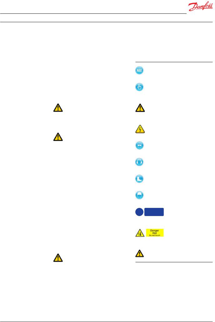
1.2 Symbols
In case the pump delivered is ATEX certified, the |
|
Indicates something to be noted by the |
||
additional ATEX instruction must also be read.. |
|
reader |
|
|
The PAHT pumps must not be used for other |
|
|
|
|
|
|
|
||
purposes than those recommended and |
|
Indicates a situation which will or could |
||
specified without first consulting your local |
|
result in damage to the pump and its |
||
pump distributor.. |
|
function |
|
|
|
|
|
|
|
|
|
|
Indicates a situation which will or could |
|
|
|
|
result in personal injury and/or damage |
|
Use of the pump in other applications not |
|
to the pump |
||
suitable for the pump unit can cause damages to |
|
|
|
|
the pump unit, with risk of personal injury.. |
|
Electrical hazard - Indicates a high- |
||
|
|
|
||
|
|
|
voltage warning |
|
All personnel being responsible for operation |
|
|
|
|
|
Safety glasses required |
|||
and maintenance of the pump unit must read |
|
|
|
|
and fully understand these instructions, |
|
|
|
|
especially the section “Safety”, before: |
|
Hearing protection required |
||
• Transportation of the pump unit |
|
|||
|
|
|
||
• |
Lifting the unit |
|
|
|
• Installing the pump unit |
|
|
|
|
• Connecting the pump unit to the water |
|
Safety shoes required |
||
|
system |
|
|
|
• Connecting the electric motor and instru- |
|
|
|
|
|
mentation |
|
|
|
• |
Commissioning the unit |
|
Safety helmet required |
|
• Servicing the motor pump unit, mechanical |
|
|
|
|
|
and electrical parts |
|
|
|
• Decommissioning the motor pump unit |
! |
Protective |
Protective garments |
|
|
|
|||
The pump must always be installed and used in |
garments |
|||
must be worn |
must be worn |
|||
accordance with existing national/local |
|
|
|
|
sanitary, safety regulations and laws. |
|
|
|
|
It is the responsibility of the safety officer or |
|
|
Danger HOT. |
|
|
|
|||
the chief operator to assure compliance with all |
|
|
Do not touch |
|
|
|
|||
local regulations that are not taken into |
|
|
|
|
account in this manual. |
|
|
|
|
|
|
|
|
|
|
|
|
Electrical |
Electrical hazard |
|
|
|
hazard |
|
Changing the pumps’ or pump units’ operational limits and hardware:
•Changes to the delivered pump or motor pump system may only be done with a written approval from Danfoss High Pressure Pumps..
•Operation outside the Danfoss specifications requires a written approval from Danfoss High Pressure Pumps..
•If any changes are made without written approval the warranty will automatically become void..
180R9287 |AQ073186503097en-001001 | IOM PAHT 2-12.5 pumps | 01.2022 |
5 |
Operation guide | Installation, Operation and Maintenance Manual for PAHT 2-12.5 pumps
1.3 Manufacturer and customer service |
Your local Danfoss pump distributor can be |
||
address: |
|
found on our homepage.. |
|
Danfoss A/S |
|
1.4 Country specific information |
|
High Pressure Pumps |
1.4.1 United Kingdom |
||
Nordborgvej 81, |
|
UK importer: |
|
DK-6430 Nordborg |
|
||
Denmark |
|
Danfoss Ltd.. |
|
|
|
|
22 Wycombe End |
Telephone: +45 7488 2222 |
HP9 1NB Beaconsfield |
||
Fax: |
+45 7445 3831 |
United Kingdom |
|
Email: |
highpressurepumps@danfoss.com. |
|
|
Web: |
hpp. danfoss. |
.com. |
|
|
|
|
|
2.Safety
2.1General information
Dangers that can arise from not following the instructions:
When the pump or pump system is managed by untrained personnel, there is a danger of:
•Death or fatal injuries
•Costly damages and claims
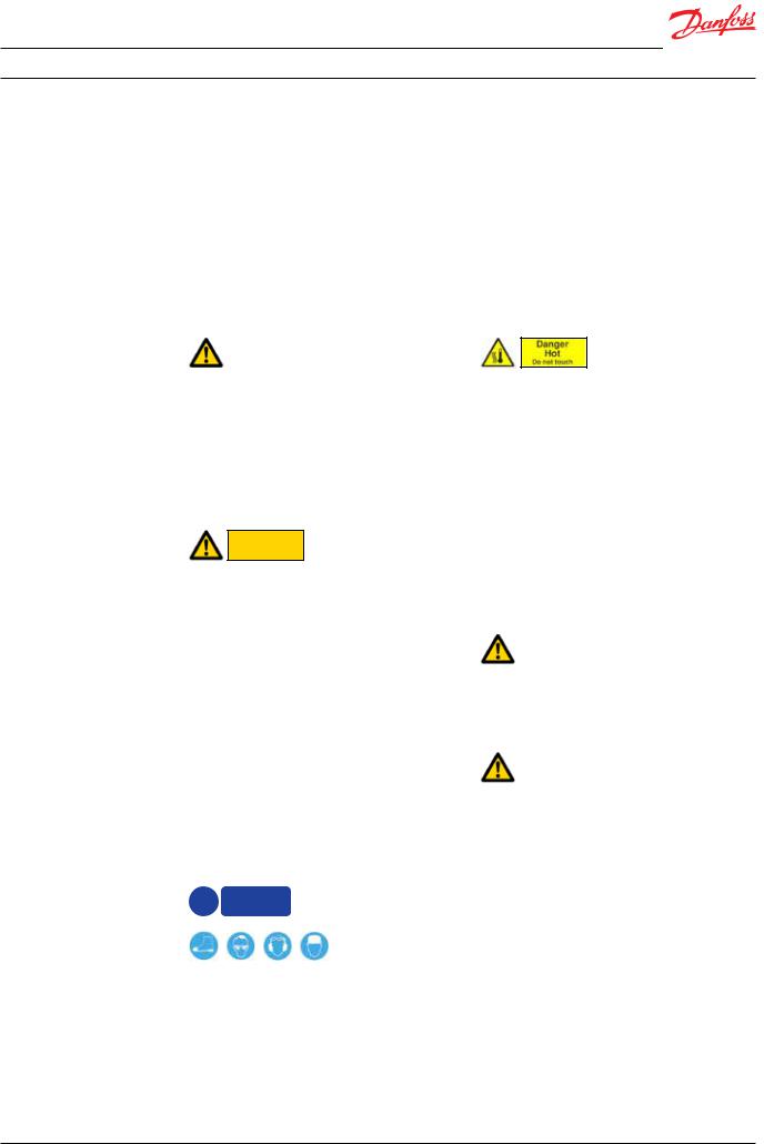
Electrical
hazard
All electrical installation work must only be carried out by authorized personnel in accordance with EN60204-1 and/or local regulations..
It is recommended to install a lockable circuit breaker to avoid inadvertent starting and/or electrical hazard.. The lockable circuit breaker must be used during installation, operation and maintenance..
It is recommended to place a local safety switch nearby the pump, enabling service personnel to cut power for the electric motor..
Protect the motor and other electrical equipment from overloads with suitable equipment..
In case the pump delivered is ATEX certified, the additional ATEX instruction must also be read..
!Protective garments must be worn
Under certain operational conditions the surface of the pump can be above 60°C / 140°F..
Under these conditions the pump must be labelled with a “Danger Hot” sign..
When using an electric motor, the motor must always be supplied with adequate cooling ventilation..
When using an electric motor together with a VFD (Variable Frequency Drive), the motor must be designed for operation with VFD.. VFD operation may increase the temperature inside the electric motor if the motor is not designed for VFD operation.. This can damage the motor and cause unintended breakdown..
Before start-up, the settings for all protective devices, such as sensors/switches and safety valves must be verified and free flow from safety valves must be ensured..
All pipe and hose connections must be stressfree mounted, securely fastened to the pump and well supported.. Improper installation will or could result in personal injury and/or damage to the pump..
Use of this manual does not relieve operation and maintenance personnel of the responsibility of applying good judgment when operating and maintaining the pump and its components.
Always wear suitable safety clothing when handling the pump..
When working near the pump system, safety shoes, safety glasses, hearing protection and safety helmet must always be worn..
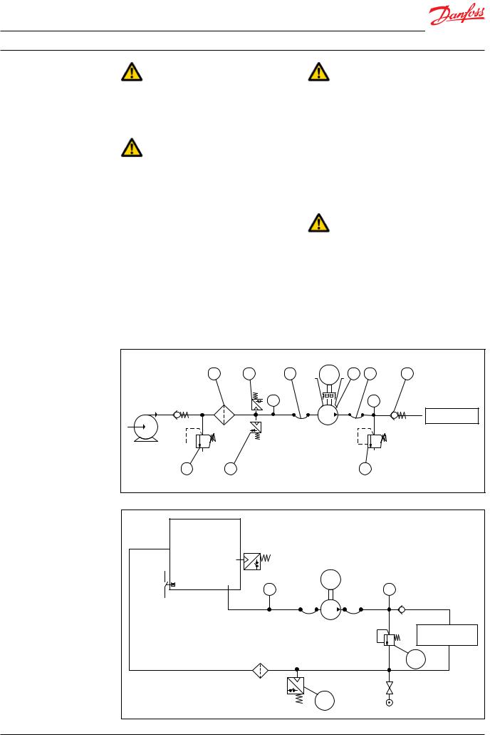
2.2 Preferred system design
Danfoss recommends to build systems with a high degree of safety.. Danfoss preferred system design and P&ID are found in appendix 1, Data sheet, and appendix 2, Instruction..
6 |
180R9287 |AQ073186503097en-001001 | IOM PAHT 2-12.5 pumps | 01.2022 |
|
Operation guide | Installation, Operation and Maintenance Manual for PAHT 2-12.5 pumps
It is always the system builders´ responsibility that the system design does not cause any kind of hazard and is adapted to local regulations and standards..
Proper installation, proper start up and shutdown devices as well as high-pressure protection equipment is essential..
2.3 Commissioning and servicing the unit
It is recommended that commissioning and servicing are carried out by a minimum of two people, where one is acting as a supervisor..
•Do not try to lift the pump unit manually; most of the pumps weigh more than
20 kilos, see specific weight for the pump in the appendix 1, Data sheet..
•Always bleed the pump prior to initial start-up..
•Do not mount the pump without the bell housing and a flexible coupling..
•Do not try to start the unit before the system components are mounted, bleeded and adjusted..
•Flush the system throughly before connecting the pump or pump unit..
•Check rotation direction of the motor before mounting the pump..
2.4Adhere to the following important points
•Before using the pump/pump unit it is very important to read and understand this user manual..
2.5 In case of doubt
Please contact Danfoss A/S in case of doubt.. Contact information are listed in section 1..3, Manufacturer and customer service address..
3.Technical data
3.1Approved applications and operational limits for the pumps
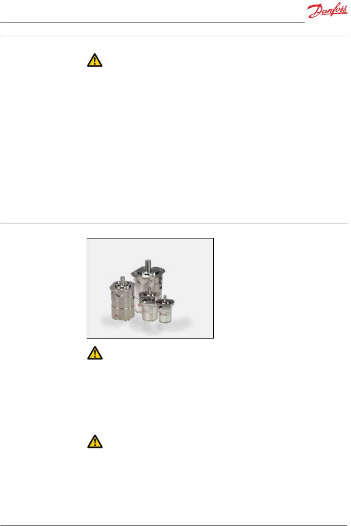
The pump and the pump units are designed for the use in systems with technical water.
The PAHT G pumps must not be used for other purposes than those recommended and specified without first consulting your local pump distributor.
Use of the pump in other applications not suitable for the pump unit can cause damages to the pump unit, with risk of personal injury.
For system integration of the pumps, please see appendix 1, Data sheet and appendix 2, Instruction.
3.2Application range
See appendix 1, Data sheet..
3.3Electric motor data
See recommended motor in appendix 1, Data sheet or appendix 3, IOM for motors.. The motors mentioned are the most common used motors by Danfoss High Pressure Pumps..
3.4 Noise and vibration
Noise level for a pump unit with a ”standard” motor measured according to EN ISO 3744:2010, see appendix 1, Data sheet.. Possibilities to reduce noise and vibration are described in the same Data sheet..
3.5 Dimension drawings
Dimensions of the different pumps can be found in appendix 1, Data sheet..
3.6 Space requirement
When doing service or replacing the complete pump unit, it is recommended to have sufficient space available around the pump in order to ensure easy access.. Sufficient space means at least 1 meter/40 inches around the pump.. When working with high pressures, it is important to have the right space available around the pump as stated in the safety requirements..
180R9287 |AQ073186503097en-001001 | IOM PAHT 2-12.5 pumps | 01.2022 |
7 |

Operation guide | Installation, Operation and Maintenance Manual for PAHT 2-12.5 pumps
3.7 Filtration
(10µm absolute [β10 ≥ 5000])
Requirements are specified in appendix 1, Data sheet and appendix 2, Instruction..
Danfoss recommends not to build a filter bypass function or use filters with an integrated bypass.. If the above recommendation is not followed the warranty for the pump will automatically become void..
It should be possible to monitor the condition of the filter via the differential/delta pressure across the filter..
Using insufficient filtration or a filter bypass can cause a failure or decreased service life of the pump.
3.8 Properties of water
It is recommended NOT to use the pump for other media than specified in the Data sheet..
3.9 Air bubbles
Large bubbles in a pressurised system can result in damage to piping, equipment and the pump..
All air must be bleeded from both the low- pressure and high-pressure side before the system is pressurised.. Special consideration should be given in order to minimize air bubbles in the feed flow.. Air bubbles can cause cavitation..
3.10 Chemicals
The pumps should not be exposed to any chemicals that can result in damage to piping, equipment and internal parts of the pump..
4. Arrival inspection, |
4.1 Arrival inspection |
transportation, |
The pump is packed in a cardboard or wood box |
handling, lifting and |
with plugs in the port connections to protect the |
storage |
pump from damage during transportation.. |
|
When the shipment has arrived it is important to |
|
check the pump for any damages.. The name |
|
plate/type designation must be in accordance |
|
with the delivery note and your order.. |
|
In case of damage and/or missing parts, a report |
|
should be documented and presented to the |
|
carrier at once.. |
4.2 Warning
Before any lifting operation is performed, environmental conditions must be taken into consideration (Ex-rated areas, wind speed, wet/ dry conditions, lifting height, etc..)..
4.3 General safety information
Personnel involved in lifting and transporting the equipment (see Safety, chapter 2) must be trained in handling and safety procedures when lifting heavy loads.. Many of the pumps and pump units weigh more than 20 kilos, which requires lifting slings and suitable lifting devices;
e..g.. an overhead crane or industrial truck to be used as minimum..
4.4 Transport and handling
Small pumps which have a weight below 20 kilos (weight can be found in appendix 1, Data sheet) can be handled by hand if they are not mounted together with an electric motor.. The weight of a small pump with a motor will be above 20 kilos..
8 |
180R9287 |AQ073186503097en-001001 | IOM PAHT 2-12.5 pumps | 01.2022 |
|

Operation guide | Installation, Operation and Maintenance Manual for PAHT 2-12.5 pumps
Pumps which have a weight above 20 kilos (see appendix 1, Data sheet) must be handled by using lifting eyes and slings..
When the pump is mounted together with an electric motor, the pump unit always weigh more than 20 kilos and must be handled by using slings around the pump unit..
See below examples of where to/not to attach the lifting slings on the pump unit:
Correct lifting with 2 separate slings:
Wrong lifting:
When lifting the pump unit, one sling must be attached to the electric motor and one sling around the pump..
Only some motors and pumps have specific lifting eyes..
Do not use connections/nozzles for lifting! Do not use only one sling!
Make sure that the unit/load is balanced before lifting.. The centre of the mass varies from pump/ pump unit size to pump/pump unit..
How to mount the pump and the electric motor correctly, see appendix 1, Data sheet or appendix 2, Instruction..
Incorrect lifting can result in personal injury and/or damage to the pump unit, see appendix 2, Instruction.
4.5 Return to supplier
Please see maintenance chapter 7..
4.6 Storage
Each pump is tested before shipment, and will therefore contain water.. For storage temperature and frost protection see appendix 2, Instruction..
The pumps are NOT delivered frost protected from the factory.
180R9287 |AQ073186503097en-001001 | IOM PAHT 2-12.5 pumps | 01.2022 |
9 |
Operation guide | Installation, Operation and Maintenance Manual for PAHT 2-12.5 pumps
5.Installation and commissioning
5.1Important dimensions
Physical dimensions and connections of the pump unit are described in appendix 1, Data sheet..
5.2 Cleanliness
It is very important that the tubes and pipes are completely clean: no dirt, chips or burrs are allowed..
Flush all piping before connecting the high- pressure pump to ensure the system is clean.. Internal surfaces of the piping must not be corroded.. If dirt or rust is not removed, the pump and the valves can be damaged.. In worst case the pump can be damaged beyond repair!
Open system design
5.3 Fluid temperature
Before start-up, the fluid and pump housing temperature must be within the specified temperature range listed in appendix 1, Data sheet..
5.4 Electrical data
Check voltage, current frequency and rated power on the electric motor and VFD settings on the name plate placed on both the motor and the VFD..
5.5 Local regulations
Commissioning must always be done in accordance with valid regulations and local standards..
1 |
4 |
5 |
<![if ! IE]> <![endif]>M |
2 |
5 |
6 |
|
|
|
|
|
|
|
|
|
PI |
|
|
PI |
|
|
|
|
|
|
|
SYSTEM |
8 |
3 |
|
|
|
7 |
|
Closed system design (not applicable for PAHT/PAHT G 256-308)
|
Reservoir |
|
|
<![if ! IE]> <![endif]>M |
|
|
PI |
PI |
|
|
System |
|
|
1 |
|
2 |
|
10 |
180R9287 |AQ073186503097en-001001 | IOM PAHT 2-12.5 pumps | 01.2022 |
|
|
|
Operation guide | Installation, Operation and Maintenance Manual for PAHT 2-12.5 pumps
5.6 Pre mounting checklist, based on Danfoss preferred system designs
Table 1: Check points when assembling and commissioning system
|
Check points |
Comment |
OK ? |
|
|
|
|
CP1 |
Ensure that the environmental conditions are safe.. |
See Arrival inspection, |
|
|
|
transportation, handling, |
|
|
|
lifting and storage, chapter 4.. |
|
|
|
|
|
CP2 |
Minimum and maximum start-up temperature for fluid and |
See Data sheet or Instruction, |
|
|
pump.. |
appendices 1 and 2.. |
|
|
|
|
|
CP3 |
Filtration condition (10µm absolute (β10 ≥ 5000) |
See Danfoss requirements in |
|
|
|
Data sheet and Instruction, |
|
|
|
appendices 1 and 2 |
|
|
|
|
|
CP4 |
Power supply for electric motor and VFD.. |
See Data sheet for the used |
|
|
|
motor and VFD.. |
|
|
|
|
|
CP5 |
Safety circuit / breaker must be sized for the motor and |
See Data sheet for the used |
|
|
environment (corrosion and humidity) |
safety circuit.. |
|
|
|
|
|
CP6 |
Bolts and screws must conform to environmental conditions |
|
|
|
as well as fluid and torque requirements.. |
|
|
|
|
|
|
CP7 |
Instrumentation, pressure switch should be designed to |
See Data sheet for the used |
|
|
conform to the environment (corrosion and humidity).. |
equipment.. |
|
|
|
|
|
CP8 |
Check the factory settings of the safety/relief valves or |
See Data sheets for the used |
|
|
pressure relief valves (1).. |
valves.. |
|
|
|
|
|
CP9 |
Check the settings of the pressure transmitter/switch (2) set |
See Data sheet or Instruction, |
|
|
at min.. inlet pressure.. |
appendices 1 and 2.. |
|
|
|
|
|
CP10 |
Check that all pressure indicators (PI) are selected to be able |
Scaling should at least be 1 Bar |
|
|
to measure the system pressure range.. |
or more precise.. |
|
|
|
|
|
CP11 |
Check coupling distance ( air gab – movement of the spider ) |
3 – 5 mm |
|
|
|
|
|
CP12 |
Check correct connections on the pump ( in & outlet) |
|
|
|
|
|
|
CP13 |
Check piping for possible air gaps.. |
|
|
|
|
|
|
5.7 Lifting and positioning
Lift the pump unit onto base (Remember vibration dampers, if needed).. Fasten the motor to the base..
See also chapter 4, Arrival inspection, transportation, handling, lifting and storage..
5.8 Mount the different equipment
(connections, pipes, tubes, check and safety/relief valves, etc.)
•The hard piping and flexible hoses used must be of proper design and must be installed in accordance with the manufacturer’s recommendations..
•Misalignment of the hard pipes may give unintended stress on the pump port connection and may damage the pump..
•Prevent excessive external pipe load..
•Do not connect piping by applying external force (use of wrenches, crane, etc..) Piping must be aligned without residual stress..
•Do not mount expansion joints so that their force applies internal pressure on the pump connections..
5.9 Electrics
All electrical installation work must be carried out by authorized personnel in accordance with EN60204-1 and/or local regulations.. (see also Safety, chapter 2)
Turn off the safety circuit breaker and lock it..
Mount the power cable on the electric motor..
If a VFD is used, adjust the protective motor switch/VFD to the current limits found on name plate of the electric motor..
5.10 Instrumentation
The pressure switch/sensor should be mounted as close to the pump as possible.. It is recommended to test the pressure/sensor switch via an instrumentation manifold..
Mount the pressure switch/sensors according to the manufacturer’s instructions..
5.11 Connections
Mount and tighten connections and check valve(s) as specified..
180R9287 |AQ073186503097en-001001 | IOM PAHT 2-12.5 pumps | 01.2022 |
11 |
Operation guide | Installation, Operation and Maintenance Manual for PAHT 2-12.5 pumps
5.12 Ensure free flow
Ensure free flow from relief valve (table 1, item 5..6, CP 8).. A blocked relief valve can cause excessive build-up of pressure and thereby cause dangerous situations and damage to the whole system..
5.13 Verify setting of safety/relief valves
Make sure, the relief valve is placed correctly (see open system design, item 1)..
Check the pressure settings on the name plate of the relief valve.. If they are within specifications, you can continue..
5.14 Bleed and remove air from the pump
Open bleeding plugs.. Keep the plugs open until the high-pressure pump is bleeded..
If the pump is submerged, remove all bleeding plugs before mounting in reservoir..
5.15 Verify direction of rotation
The direction of rotation must always follow the arrow.. The arrow is placed on the pump or pump unit..
Check the direction of rotation before mounting the pump..
Unlock the safety circuit breaker.. Start the motor for 1 second and observe the direction of rotation either looking on the fan of the motor or on the coupling through the hole in the bell housing (not available on all bell housings).. If the motor is turning the wrong direction, switch two phases in the connection box of the motor or reprogram the direction in VFD..
When the motor is turning in the right direction, the pump can be mounted..
5.16 Commissioning
5.16.1Open system
•Check if filter element is present and mounted correctly..
•Switch on the circuit breaker for both motor(s) and VFD(s)..
•Check rotation of the feed pump..
•Start feed pump..
•Bleed high-pressure pump until only water leaves the high-pressure pump.. Remember to close all bleeding and draining plugs..
•Adjust pressure relief valve to minimum setting..
•Check rotation of the high-pressure pump by description in 5..15..
•Start high-pressure pump for 2 minutes, to make sure all air is out of the system..
•Adjust pressure relief valve to working pressure..
•Check all fittings for leakage..
•Check the temperature switch/controls.. The high-pressure pump must stop if temperature is above specified set point..
•Check the pressure switch/controls.. The high-pressure pump must stop if pressure is below specified set point..
•If the system is running within the system design limits, the system is released for operation..
5.16.2Closed system
•Check if the reservoir is clean..
•Check if filter element is present and mounted correctly..
•Fill water at the reservoir using the filling valve.. Inspect immediately for leakage..
•Bleed high-pressure pump until only water leaves the high-pressure pump.. Remember to close all bleeding and draining plugs..
•Adjust pressure relief valve to minimum setting..
•Check rotation of the high-pressure pump by description in 5..15..
•Start high-pressure pump for 2 minutes, to make sure all air is out of the system..
•Check reservoir low level switch/controls.. The high-pressure pump must stop if low level switch is activated..
•Adjust pressure relief valve to working pressure..
•Check the temperature switch/controls.. The high-pressure pump must stop if temperature is above specified set point..
•Check the filter pressure switch/controls.. A warning must be given if pressure is above specified set point..
•If the system is running within the system design limits, the system is released for operation..
5.17 Check the filter condition
Evaluate contamination found in filter, replace filter elements, if necessary..
5.18Instruct operator and maintenance personnel
Before using the pump/pump unit, the personnel must be instructed in using the pump/pump unit, its function, components, documentation and safety..
Danfoss offers commissioning and service at system manufacturer’s location.. Rate quotes are offered upon request..
12 |
180R9287 |AQ073186503097en-001001 | IOM PAHT 2-12.5 pumps | 01.2022 |
|

Operation guide | Installation, Operation and Maintenance Manual for PAHT 2-12.5 pumps
6.Operation of motor pump unit
6.1General safety information
Before inspecting the pump unit, read the Safety chapter 2 in this user manual..
6.2 What to listen and look for
If one or more of the following examples are observed, please act as indicated:
A)Loose bolts – check all bolts and, if necessary, contact the maintenance department in order to have all bolts tightened to the specified torque(s)..
B)Leakage – if a small leakage from the bell housing is observed.. Contact the maintenance department..
C)Leakage – if there is a large leak, the unit should be stopped immediately.. Contact the maintenance department..
D)High frequency tones – safety/relief valves are either damaged or running very close to their design pressure, stop the unit immediately.. Contact the maintenance department..
E)Increased noise or vibration – requires the unit to be stopped immediately.. Contact the maintenance department..
F)Very high temperatures – may indicate that one or more parts are damaged inside the pump.. The pump must be stopped immediately and inspected before it is restarted.. Contact the maintenance department..
G)Drop in flow and/or pressure – may indicate wear on one or more parts inside the pump.. The pump must be stopped immediately and inspected before it is restarted.. Contact the maintenance department..
H)Other observations or troubles, please see appendix 7, Right and Wrong or appendix 6, Trouble shooting guide.. Both appendices give good advises on design, installation, wiring and troubleshooting..
If the pump is not stopped for inspection as recommended, it can lead to damage of the pump or break-down.. See also service and warranty section in appendix 1, Data sheet and appendix 2, Instruction..
Danfoss offers service of the pump at the system manufacturer’s location as well as we offer training in how to service the pump.. Quotes are offered upon request..
Danfoss recommends simultaneously to check the filter and membrane condition and to evaluate contamination; filter and membrane elements must be replaced if necessary..
7.Maintenance and service of the pump
unit |
7.1 General safety information |
|
Before servicing the pump unit, it is necessary to |
|
read and understand this user manual, especially |
|
the Safety, chapter 2.. Remember to wear suitable |
|
safety equipment according to Safety, chapter 2.. |
7.2 Service and inspection interval for the pump
Maintenance and service intervals are depending on the cleanliness level of the water, hydraulic load and temperature of the pump unit.. The most important parameter is the filtration of the water..
See the section Service and warranty in the appendix 1, Data sheet and appendix 2, Instruction..
For spare parts and service tools, please see appendix 4, Parts list..
Danfoss offers service of the pump at the system manufacturer’s location and training in how to service the pump.. Quotes are offered upon request..
7.3Shut down of the system
A)Stop the high-pressure pump..
B)Release the pressure..
C)Stop the feed pump if used..
D)Switch off the safety circuit breaker for both the high-pressure pump, feed pump and VFD and lock them.. Only personnel servicing the pump unit should be able to unlock/activate the switch again..
E)Open bleeding and drain plugs.. Wait until the pump and system are emptied for water..
180R9287 |AQ073186503097en-001001 | IOM PAHT 2-12.5 pumps | 01.2022 |
13 |

Operation guide | Installation, Operation and Maintenance Manual for PAHT 2-12.5 pumps
F)Slowly unscrew and remove the bolts and gaskets from the inlet/outlet hoses or pipes, be careful about jets of water.. Be aware that the system can be pressurized..
G)Attach the lifting equipment to the pump unit.. For instructions on lifting the complete pump unit, see chapter 4, Arrival inspection, transportation, handling, lifting and storage..
H)For the small pumps, unscrew the bolts holding the pump to the bell housing and for the bigger pumps, unscrew the bolts/ nuts from the pump and bell housing to the motor and afterwards unscrew the bolts/nuts holding the pump and bell housing..
I)Carefully pull the pump out of the bell housing by using lifting equipment, if necessary..
J)Hold the pump in different positions above a drip tray; this should allow most of the water trapped in the pump to drain.. Clean and dry the pump surface and plug the bleeding and draining plugs..
K)Move the pump to a clean and safe location where the pump can be inspected/ serviced..
7.4Disassembling and assembling the pump unit
A)Remove all connections from the pump..
B)Disassemble the pump according to the Disassembling and Assembling Instruction (available at
www.. danfoss..high-pressurepumps..com).. Clean all the parts and surfaces with a fluid compatible with the materials found in the pump.. Wipe the parts clean and dry with a lint-free clothing..
C)Inspect all parts including shaft seal and if necessary, replace them; see appendix 4, Parts list..
D)If the pump is going to be returned to Danfoss for repair or a warranty claim, it is important to contact Danfoss in order to receive a return number and a form to fill out with product information.. A copy of the form together with contact information and reason for returning should be sent to the email address on the form.. The same documents should be attached to the shipment..
Returns without a return number will be rejected !!!
7.5Assembling the pump unit
Assemble the pump according to the Disassembling and Assembling Instruction (available at hpp..danfoss..com)..
7.6Procedure for mounting the pump back onto electric motor
Mount the flexible coupling and bell housing according to appendix 2, Instruction..
7.7Getting the pump unit back into operation
Find instructions of how to put the pump unit back into operation in chapter 4, Arrival inspection, transportation, handling, lifting and storage and Installation and commissioning, chapter 5..
7.8Storage of the pump
If the pump has to be shut down for a longer period, instructions can be found in appendix 2, Instruction..
14 |
180R9287 |AQ073186503097en-001001 | IOM PAHT 2-12.5 pumps | 01.2022 |
|

Operation guide | Installation, Operation and Maintenance Manual for PAHT 2-12.5 pumps
8.Troubleshooting and scrapping criteria
8.1General safety information
Before inspecting the pump unit, it is necessary to read and understand this user manual, especially the Safety chapter 2..
Remember to wear suitable safety equipment according to Safety chapter 2..
8.2 Operational conditions which can cause pump failures
The following conditions can cause a pump failure :
•The pump is running dry..
•The inlet pressure is too high..
•The inlet pressure is too low..
•The temperature of the fluid is too high..
•The ambient temperature is too high..
•The pump is running against a blocked port/closed manual valve..
•The pump is operating at a pressure out of specification..
•The pump is running with a non-specified/ approved fluid..
•The pump is running in the wrong direction..
•The filtration is insufficient..
•There is excessive mechanical load on the shaft coupling and piping..
8.3 Mechanical failure
If the pump is running dry, the temperature will quickly increase which can cause burns..
If there is any leakage at start-up or during operation, a high pressure jet can cause eye or skin damage..
Leakage can result in flooding, which can cause slipping, tripping or falling..
If water is dripping into the electric motor; it can cause electric shock, fire, short of circuit or even death.. When mounting the pump vertically, always mount the motor above the pump to avoid water leaking into the electric motor..
Electrical
hazard
8.4 Electrical failure
If the wiring of the electric motor is incorrect or the ground connection is missing, it can cause electric shock, burn damages, fire or even death..
If a VFD is used and wrongly programmed, it can damage the pump and lead to high temperatures or other dangers..
All electrical installation must be carried out by authorized personnel in accordance with EN60204-1 and/or local regulations..
8.5 Responsibility
Danfoss takes no responsibility for any abnormal injuries, risks or damages that could arise caused by abnormal conditions, vibrations, corrosion, abrasives, foreign objects or excessive temperatures and shall not be liable for any consequential or incidental damages..
8.6 Scrapping criteria
Whether the pump can be repaired or need to be scrapped, depends on in which conditions the internal parts are, or how damaged the whole unit is.. Please use appendix 5, Trouble shooting guide as guideline or send the pump to Danfoss headquarter in Denmark for evaluation..
For other observations or troubles, please see appendix 6, Right and Wrong which gives good advises regarding design, installation, wiring and troubleshooting..
In case the pump needs to be scrapped, please follow your local environmental rules..
180R9287 |AQ073186503097en-001001 | IOM PAHT 2-12.5 pumps | 01.2022 |
15 |

Operation guide | Installation, Operation and Maintenance Manual for PAHT 2-12.5 pumps
16 |
180R9287 |AQ073186503097en-001001 | IOM PAHT 2-12.5 pumps | 01.2022 |
|
Operation guide
Appendices
PAHT 2-12.5
Installation, Operation and
Maintenance Manual
hpp.danfoss.com

Operation guide | Installation, Operation and Maintenance Manual for PAHT 2-12.5 pumps
Table of Contents |
1. |
Data sheet PAHT G 2-308 (AI106586503085en-000901) . . . . . . . . . . . . . . . . . . . . . . . . . . . . . . . . . |
19 |
|
2. |
Pump instruction PAHT 2-6..3 and PAHT 10-12..5 (180R9277) . . . . . . . . . . . . . . . . . . . . . . . . . . . |
33. . |
|
3. |
Electric motor manual (180R9230) . . . . . . . . . . . . . . . . . . . . . . . . . . . . . . . . . . . . . . . . . . . . . . . |
43. . . . . . . |
|
4. |
Parts list PAHT (AX322445815902en-000201) . . . . . . . . . . . . . . . . . . . . . . . . . . . . . . . . . . . . . . . . . . . . |
49 |
|
5. |
Trouble shooting guide for PAH, PAHT, PAHT G, PAHT 674 and PAH F pumps . . . . . . . . . . . . |
59. |
|
6. |
Right and wrong - Trouble shooting guide for water hydraulic systems (180R9042) . . . . . . . |
71 |
180R9287 |AQ073186503097en-001001 | IOM PAHT 2-12.5 pumps | 01.2022 |
18 |
Data sheet
PAHT pumps
PAHT 2-6.3/PAHT/10-12.5/PAHT 20-25/ PAHT 50-90 and PAHT 256-308
hpp.danfoss.com

|
|
|
|
|
|
Data sheet |
PAHT 2-308 pumps |
|
|
||
|
|
|
|
|
|
Table of Contents |
Contents |
|
|
|
|
|
1. |
|
Introduction . . . . . . . . . . . . . . . . . . . . . . . . . . . . . . . . . . . . . . . . . . . . . . . . . . . . . . . . |
. . . . . . . . . . . . .20. . . . . . |
|
|
2. |
|
. Benefits. . . . . . . . . . . . . . . . . . . . . . . . . . . . . . . . . . . . . . . . . . . . . . . . . . . . . . . . . . . . . . . . . |
. . . . . . . . . . . . . . 21 |
|
|
3. |
|
Application examples . . . . . . . . . . . . . . . . . . . . . . . . . . . . . . . . . . . . . . . . . . . . . . . . . . . |
. . . . . . . . . . . . . .21. |
|
|
4. |
|
Technical data . . . . . . . . . . . . . . . . . . . . . . . . . . . . . . . . . . . . . . . . . . . |
. . . . . . . . . .22. . |
. . . . . . . . . . |
|
4..1 |
|
PAHT 2-12..5 . . . . . . . . . . . . . . . . . . . . . . . . . . . . . . . . . . . . . . . . . . . . . . . . . . . . . . . . . . . . . . |
. . . . . . . . . . . . . .22 |
|
|
5. |
|
Flow . . . . . . . . . . . . . . . . . . . . . . . . . . . . . . . . . . . . . . . . . . . . . . . . . . . . . . . . . . . . . . . . . . . . . |
. . . . . . . . . . . . . .23 |
|
|
5..1 |
|
PAHT 2-6..3 typical flow curves at max pressure . . . . . . . . . . . . . . . . . . . . . . . . . . . |
. . . . . . . . . . . . . .23 |
|
|
5..2 |
|
PAHT 10-12..5 typical flow curves at max pressure . . . . . . . . . . . . . . . . . . . |
. . . . . . . . . . . .24. |
. . . . . . . |
|
6. |
|
Motor requirements . . . . . . . . . . . . . . . . . . . . . . . . . . . . . . . . . . . . . . . . . . . . . . . . . . . . . . |
. . . . . . . . . . . . . .25 |
|
|
7. |
|
Installation . . . . . . . . . . . . . . . . . . . . . . . . . . . . . . . . . . . . . . . . . . . . . . . . . . . . . . . . . . . . . . . |
. . . . . . . . . . . . . .26 |
|
|
7.1 |
. |
Filtration . . . . . . . . . . . . . . . . . . . . . . . . . . . . . . . . . . . . . . . . . . . . . . . . . . . . . . |
. . . . . . . . . . . .26. . |
. . . . . . . . . . |
|
7. 2 |
. |
Noise . . . . . . . . . . . . . . . . . . . . . . . . . . . . . . . . . . . . . . . . . . . . . . . . . . . . . . . . . . . . . . . . . . . . |
. . . . . . . . . . . . . . 26 |
|
|
7..3 |
|
Open-system design . . . . . . . . . . . . . . . . . . . . . . . . . . . . . . . . . . . . . . . . . . . . . . . . . . . . |
. . . . . . . . . . . . . .27. |
|
|
7..4 |
|
Closed-system design (not applicable for PAHT 256-308) . . . . . . . . . . . . . . . . . . |
. . . . . . . . . . . . . .28 |
|
|
8. |
|
Dimensions and connections . . . . . . . . . . . . . . . . . . . . . . . . . . . . . . . . . . . . . . . . . . . . . |
. . . . . . . . . . . . . .29 |
|
|
8..1 |
|
PAHT 2-6..3 . . . . . . . . . . . . . . . . . . . . . . . . . . . . . . . . . . . . . . . . . . . . . . . . . . . . . . . . . . . . . . . |
. . . . . . . . . . . . . .29 |
|
|
8..2 |
|
PAHT 10-12..5 . . . . . . . . . . . . . . . . . . . . . . . . . . . . . . . . . . . . . . . . . . . . . . . . . . . . . . . . . . . . . |
. . . . . . . . . . . . . .30 |
|
|
9. |
|
. . Service. . . . . . . . . . . . . . . . . . . . . . . . . . . . . . . . . . . . . . . . . . . . . . . . . . . . . . . . . . . . . . . . . |
. . . . . . . . . . . . . . 31 |
|
1. |
Introduction |
The Danfoss range of PAHT high-pressure pumps |
|
|
|
is specifically designed for use with technical |
|
|
|
water such as: |
|
|
|
• |
Ultra-pure water that has undergone |
|
|
|
multiple reverse osmosis processes |
|
|
• |
De-ionized water |
|
|
• |
Demineralized water |
Danfoss PAHT pumps are positive displacement pumps, with axial pistons that move a fixed amount of water in each cycle.. Flow is proportional to the number of input shaft revolutions (rpm).. Unlike centrifugal pumps, they produce the same flow at a given speed independently of no matter what the discharge pressure..
20 |
180R9287 |AQ073186503097en-001001 | IOM PAHT 2-12.5 pumps | 01.2022 |
|
|
|
|
Data sheet |
PAHT 2-308 pumps |
|
|
|
|
|
|
Below sectional drawing is an example of a PAHT pump..
1: |
Mounting flange |
2: |
Shaft seal |
3: |
Connecting flange |
4: |
Port plate |
5: |
Valve plate |
6: |
Retainer plate |
7: |
Swash plate |
8: |
End cap |
9: |
Spring |
10: Piston |
|
11: Cylinder barrel |
|
12: Housing with bearing |
|
2. Benefits |
• |
Zero risk of lubricant contamination: |
|
- Pump can be installed horizontally or |
|
|
- Oil lubricants are replaced with the |
|
vertically.. |
|
|
pumped medium, water, so there is no |
|
- No pulsation dampeners necessary due |
|
|
contamination risk from the pump.. |
|
to extremely low-pressure pulsation.. |
|
• |
Low maintenance costs: |
|
- Powered by electric motors or combus- |
|
|
- Efficient design and all-stainless steel |
|
tion engines.. |
|
|
construction ensure exceptionally long |
|
- Suitable for both boosted inlet |
|
|
lifetime.. When Danfoss specifications |
|
pressure and water supply from a tank.. |
|
|
are met, service intervals of up to 8,000 |
|
- No need for cooling circuits due to very |
|
|
hours can be expected.. Service is easy, |
|
high mechanical efficiency.. |
|
|
and can be carried out on site due to |
• |
Certified quality: |
|
|
the simple design and few parts.. |
|
- Fulfills the stringent hygiene require- |
|
• |
Low energy costs: |
|
ments, VDI 6022, HACCP.. |
|
|
- The highly efficient axial piston design |
|
- Certificates: |
|
|
provides the lowest energy consump- |
|
ISO 9001, ISO 14001 |
|
|
tion of any comparable pump on the |
|
API available on request |
|
|
market.. |
|
|
•Easy installation:
-The lightest and most compact design available..
3. |
Application examples |
• |
High-pressure cleaning with ultra-pure |
|
|
|
water, as used in the manufacturing of |
|
|
|
flat-panel displays and many other |
|
|
|
electronic products.. |
|
|
• |
High-pressure cleaning with ultra-pure |
|
|
|
water, as used in the manufacturing of |
|
|
|
parts for the automobile industry.. |
|
|
• |
Adiabatic cooling systems to replace or |
|
|
|
supplement standard A/C systems in server |
|
|
|
rooms and factories.. |
•Humidification in office buildings, electronic component manufacturing, dairies, greenhouses, etc..
•Dust suppression and odor control systems, for example in paper, textile and wood production..
•Reduction of NOx emissions in diesel engines and gas turbines..
•Gas turbine by inlet fogging and fuel wash systems. .
180R9287 |AQ073186503097en-001001 | IOM PAHT 2-12.5 pumps | 01.2022 |
21 |

|
|
|
|
|
|
|
|
|
|
|
|
Data sheet |
PAHT 2-308 pumps |
|
|
|
|
|
|
|
|
||
|
|
|
|
|
|
|
|
|
|
|
|
4. |
Technical data |
4.1 PAHT 2-12.5 |
|
|
|
|
|
|
|
|
|
|
|
|
|
|
|
|
|
|
|
|
|
|
|
Pump size |
|
2 |
3.2 |
4 |
6.3 |
10 |
|
12.5 |
|
|
|
|
|
|
|
|
|
|
|
|
|
|
|
Code number PAHT |
180B0031 |
180B0077 |
180B0030 |
180B0029 |
180B0032 |
180B0033 |
|
||
|
|
|
|
|
|
|
|
|
|
|
|
|
|
Housing material |
AISI 304 |
AISI 304 |
AISI 304 |
AISI 304 |
AISI 304 |
AISI 304 |
|
||
|
|
|
|
|
|
|
|
|
|
|
|
|
|
Geometric |
cm³/rev |
2 |
3..2 |
4 |
6..3 |
10 |
12..5 |
|
|
|
|
displacement |
|
|
|
|
|
|
|
|
|
|
|
in³/rev |
0..12 |
0..20 |
0..24 |
0..38 |
0..61 |
0..76 |
|
||
|
|
|
|
||||||||
|
|
|
|
|
|
|
|
|
|
|
|
|
|
Pressure |
|
|
|
|
|
|
|
|
|
|
|
|
|
|
|
|
|
|
|
|
|
|
|
Min.. outlet |
barg |
30 |
30 |
30 |
30 |
30 |
30 |
|
|
|
|
pressure |
|
|
|
|
|
|
|
|
|
|
|
psig |
435 |
435 |
435 |
435 |
435 |
435 |
|
||
|
|
|
|
||||||||
|
|
|
|
|
|
|
|
|
|
|
|
|
|
Max.. outlet |
barg |
100 |
100 |
100 |
100 |
140 |
140 |
|
|
|
|
pressure |
|
|
|
|
|
|
|
|
|
|
|
psig |
1450 |
1450 |
1450 |
1450 |
2031 |
2031 |
|
||
|
|
|
|
||||||||
|
|
|
|
|
|
|
|
|
|
|
|
|
|
Inlet pressure, |
barg |
0-4 |
0-4 |
0-4 |
0-4 |
0-4 |
0-4 |
|
|
|
|
continuous |
|
|
|
|
|
|
|
|
|
|
|
psig |
0-58 |
0-58 |
0-58 |
0-58 |
0-58 |
0-58 |
|
||
|
|
|
|
||||||||
|
|
|
|
|
|
|
|
|
|
|
|
|
|
Max.. inlet 1) |
barg |
4 |
4 |
4 |
4 |
4 |
4 |
|
|
|
|
pressure, peak |
|
|
|
|
|
|
|
|
|
|
|
psig |
58 |
58 |
58 |
58 |
58 |
58 |
|
||
|
|
|
|
||||||||
|
|
|
|
|
|
|
|
|
|
|
|
|
|
Speed |
|
|
|
|
|
|
|
|
|
|
|
|
|
|
|
|
|
|
|
|
|
|
|
Min.. speed |
rpm |
1000 |
1000 |
1000 |
1000 |
1000 |
1000 |
|
|
|
|
|
|
|
|
|
|
|
|
|
|
|
|
Min.. speed, |
rpm |
1000 |
1000 |
1000 |
1000 |
1000 |
1000 |
|
|
|
|
continuous |
|
||||||||
|
|
|
|
|
|
|
|
|
|
|
|
|
|
|
|
|
|
|
|
|
|
|
|
|
|
Max.. speed |
rpm |
3000 |
3000 |
3000 |
3000 |
2400 |
2400 |
|
|
|
|
|
|
|
|
|
|
|
|
|
|
|
|
Typical flow - Flow curves available in section 5 |
|
|
|
|
|
|
|||
|
|
|
|
|
|
|
|
|
|
|
|
|
|
1000 rpm at |
l/min |
0..7 |
2..0 |
3..0 |
5..5 |
7..6 |
10..2 |
|
|
|
|
max.. pressure |
|
||||||||
|
|
|
|
|
|
|
|
|
|
|
|
|
|
|
|
|
|
|
|
|
|
|
|
|
|
1500 rpm at |
l/min |
1..7 |
3..6 |
5..0 |
8..6 |
12..6 |
16..5 |
|
|
|
|
max.. pressure |
|
||||||||
|
|
|
|
|
|
|
|
|
|
|
|
|
|
|
|
|
|
|
|
|
|
|
|
|
|
1200 rpm at |
gpm |
0..3 |
0..7 |
1..0 |
1..8 |
2..5 |
3..3 |
|
|
|
|
max.. pressure |
|
||||||||
|
|
|
|
|
|
|
|
|
|
|
|
|
|
|
|
|
|
|
|
|
|
|
|
|
|
1800 rpm at |
gpm |
0..6 |
1..2 |
1..6 |
2..7 |
4..0 |
5..3 |
|
|
|
|
max.. pressure |
|
||||||||
|
|
|
|
|
|
|
|
|
|
|
|
|
|
|
|
|
|
|
|
|
|
|
|
|
|
Typical motor size |
|
|
|
|
|
|
|
|
|
|
|
|
|
|
|
|
|
|
|
|
|
|
|
1500 rpm at |
kW |
0..75 |
1..1 |
1..5 |
2..2 |
4..0 |
5..5 |
|
|
|
|
max.. pressure |
50 Hz |
|
|||||||
|
|
|
|
|
|
|
|
|
|
||
|
|
|
|
|
|
|
|
|
|
|
|
|
|
1800 rpm at |
hp |
1..0 |
1..5 |
2..0 |
3..0 |
7..5 |
7..5 |
|
|
|
|
max.. pressure |
60 Hz |
|
|||||||
|
|
|
|
|
|
|
|
|
|
||
|
|
|
|
|
|
|
|
|
|
|
|
|
|
Torque at max.. |
Nm |
4..4 |
6..7 |
8..1 |
12..4 |
25..6 |
31..7 |
|
|
|
|
outlet pressure |
|
|
|
|
|
|
|
|
|
|
|
lbf-ft |
3..2 |
4..9 |
6..0 |
9..2 |
18..9 |
23..4 |
|
||
|
|
|
|
||||||||
|
|
|
|
|
|
|
|
|
|
|
|
|
|
Media |
°C |
2-50 |
2-50 |
2-50 |
2-50 |
2-50 |
2-50 |
|
|
|
|
temperature |
|
|
|
|
|
|
|
|
|
|
|
°F |
37-122 |
37-122 |
37-122 |
37-122 |
37-122 |
37-122 |
|
||
|
|
|
|
||||||||
|
|
|
|
|
|
|
|
|
|
|
|
|
|
Ambient |
°C |
0-50 |
0-50 |
0-50 |
0-50 |
0-50 |
0-50 |
|
|
|
|
temperature |
|
|
|
|
|
|
|
|
|
|
|
°F |
32-122 |
32-122 |
32-122 |
32-122 |
32-122 |
32-122 |
|
||
|
|
|
|
||||||||
|
|
|
|
|
|
|
|
|
|
|
|
|
|
Sound |
dB(A) |
76 |
76 |
76 |
76 |
75 |
75 |
|
|
|
|
pressure level 2) |
|
||||||||
|
|
Weight |
kg |
4..4 |
4..4 |
4..4 |
4..4 |
7..7 |
7..7 |
|
|
|
|
|
|
|
|
|
|
|
|
|
|
|
|
|
lbs |
9..7 |
9..7 |
9..7 |
9..7 |
17..0 |
17..0 |
|
|
|
|
|
|
|
|
|
|
|
|
|
|
1)1% per minute peak, 10% per minute during start up..
2)Measurements according to EN ISO 3744: 2010 / dB(A) [LPA, 1m] values are calculated.. Measured at max pressure and rpm for a motor pump unit..
22 |
180R9287 |AQ073186503097en-001001 | IOM PAHT 2-12.5 pumps | 01.2022 |
|
|
|
|
|
|
|
|
Data sheet |
PAHT 2-308 pumps |
|
|
|
|
||
|
|
|
|
|
|
|
|
5. Flow |
The flow (Q eff) at various pressure (pmax) can be |
At zero pressure the true flow equals the |
|
||||
|
calculated with the following equation: |
theoretical flow Q (th).. |
|
||||
|
Q eff = Q (th) – [(Q (th) – Q (p max)) x (p / p max)] |
|
|
|
|
||
|
|
|
|
|
|
|
|
|
|
|
|
Q (th): |
Theoretical flow (l/min / gpm) |
|
|
|
The theoretical flow can be calculated with the |
Q (pmax): |
Flows at max.. pressure (l/min and |
|
|||
|
following equation: |
p max: |
gpm), see 4..1-4..4 |
|
|||
|
|
V x n |
Max pressure (barg / psig) |
|
|||
|
|
p: |
Pressure (barg / psig) |
|
|||
|
Q (th) = |
|
|
V: |
Displacement (cm3 / rev..) |
|
|
|
|
|
|||||
|
1000 |
|
n: |
Motor speed (rpm) |
|
||
|
|
|
|
|
|
|
|
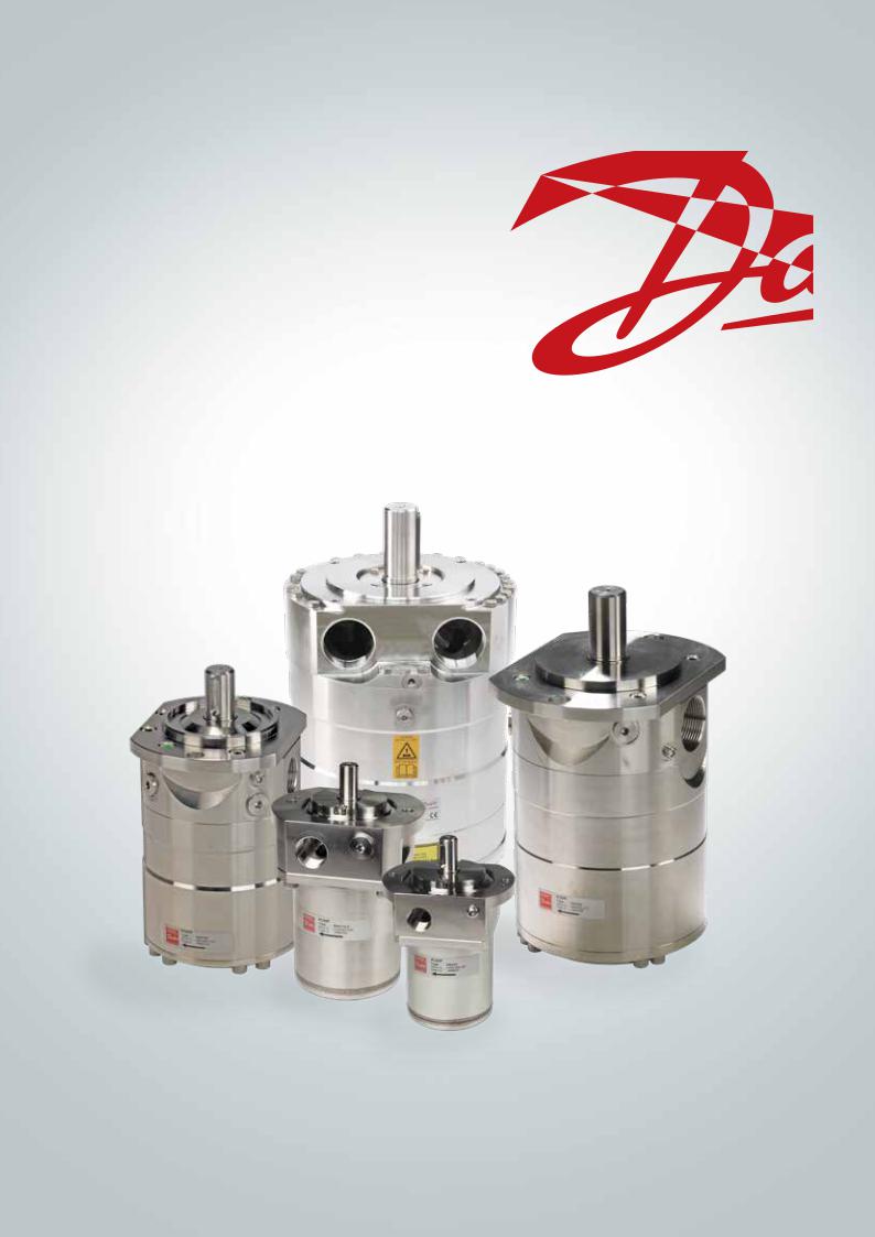
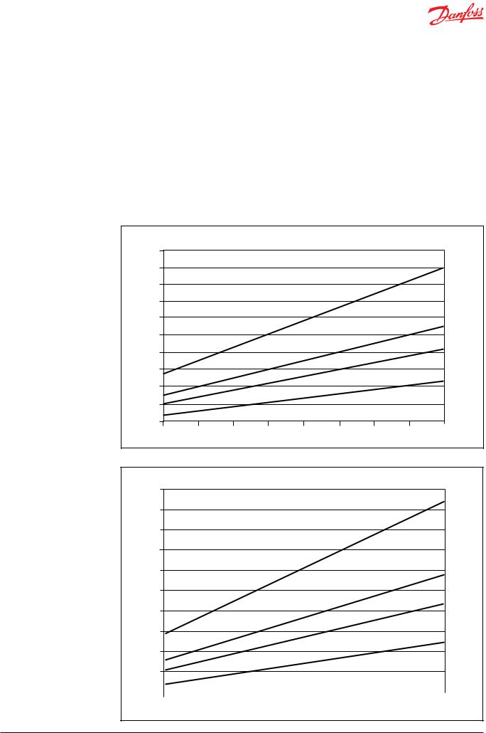
5.1PAHT 2-6.3 typical flow curves at max pressure
l/min |
|
|
|
|
|
|
|
|
20 |
|
|
|
|
|
|
|
|
18 |
|
|
|
|
|
|
|
PAHT 6.3 |
16 |
|
|
|
|
|
|
|
|
14 |
|
|
|
|
|
|
|
|
12 |
|
|
|
|
|
|
|
PAHT 4.0 |
|
|
|
|
|
|
|
|
|
10 |
|
|
|
|
|
|
|
|
8 |
|
|
|
|
|
|
|
PAHT 3.2 |
|
|
|
|
|
|
|
|
|
6 |
|
|
|
|
|
|
|
|
4 |
|
|
|
|
|
|
|
PAHT 2.0 |
|
|
|
|
|
|
|
|
|
2 |
|
|
|
|
|
|
|
|
0 |
|
|
|
|
|
|
|
rpm |
1000 |
1250 |
1500 |
1750 |
2000 |
2250 |
2500 |
2750 |
3000 |
gpm |
|
|
|
|
|
|
|
|
5.0 |
|
|
|
|
|
|
|
|
PAHT 6.3
4.5
4.0
3.5
3.0
PAHT 4.0
2.5
PAHT 3.2
2.0
1.5
PAHT 2.0
1.0
0.5
0 |
|
|
|
|
|
|
|
|
|
|
|
|
|
|
rpm |
|
|
|
|
|
|
|
|
|
|
|
|
|
|
||
1000 |
1250 |
1500 |
1750 |
2000 |
2250 |
2500 |
2750 |
3000 |
|
||||||
180R9287 |AQ073186503097en-001001 | IOM PAHT 2-12.5 pumps | 01.2022 |
23 |
 Loading...