


Installation guide
Pressure switch
KPU
<![endif]>060R9768
Application |
|
<![if ! IE]> <![endif]>060R9768 |
|
|
|
KPU dual pressure switches are for use on commercial |
– convertible manual or automatic on LP and HP sides. |
|
refrigeration and air conditioning systems to protect |
Manual reset |
|
compressor against excessively low suction pressure or |
|
|
excessively high discharge pressure. |
The manual reset mechanism does not allow the pressure |
|
KPU dual pressure switches are compatible with refrigerants |
switch to automatically reset after the switch has cut out. So the |
|
listed below. KPU16W and KP16B are fail safe switches for high |
pressure switch must be manually reset by the user to enable |
|
pressure refrigerants. Standard enclosure is ~ NEMA 1. |
restart of the equipment. Manual reset is possible to operate |
|
Refrigerants: |
only after return of pressure to cut in level. Before releasing |
|
the reset it is recommended to investigate what caused the |
|
|
R22, R134a, R404A, R407A, R407C, R407F, R410A*), R422B, R422D, |
shutdown. |
|
R438A, R448A, R449A, R450A, R452A, R507A, R513A |
Convertible reset |
|
replace with: |
|
|
For complete list of approved refrigerants, visit www.products.danfoss. |
The convertible reset feature allows to change the operation |
|
from automatic to manual by turning the selecting plate. |
|
|
com and search for individual code numbers, where refrigerants are |
|
|
The selecting plate is located between two push buttons at the |
|
|
listed as part of technical data. / |
|
|
*) R410A only for KPU 16W and KPU 16B |
top of the switch. |
|
Please refer to instruction below demonstrating how to select |
|
|
KPU dual pressure switches are fitted with the Single-Pole, |
|
|
reset function. |
|
|
Single-Throw (SPST) or Single-Pole Double-Throw (SPDT) |
|
|
|
|
|
switches, suitable for direct as well as indirect (with a contactor) |
|
|
control. |
|
|
Three versions of switch operation are available: |
|
|
–automatic on LP and HP sides
–automatic on LP and manual reset on HP
Product Specification
|
Code no. |
Low pressure (LP) |
|
High pressure (HP) |
Reset |
|
||||||
|
|
|
|
|
|
|
|
|
|
|
|
|
Type |
1⁄4 in |
36 in cap. |
Regulating |
Differential |
Regulating |
Differential |
Low |
|
High |
Contact system |
||
|
male flare |
tube w. 1⁄4 in |
range |
Δp |
|
range |
Δp |
pressure |
|
pressure |
|
|
|
flare nut |
[inHg] [psig] |
[psi] |
|
[psig] |
[psi] |
|
|
||||
|
|
|
|
|
|
|
||||||
|
|
|
|
|
|
|
|
|
|
|
|
|
KPU 15 |
060-5247 |
060-5248 |
6 in – 108 |
10 – 60 |
100 – 465 |
60 |
Automatic |
|
Automatic |
SPST |
||
|
|
|
|
|
|
|
|
|
|
|
|
|
KPU 15B |
060-5249 |
060-5250 |
6 in – 108 |
10 – 60 |
100 – 465 |
60 |
Automatic |
|
Man (Max.) |
(NO + NC) |
||
|
|
|||||||||||
|
|
|
|
|
|
|
|
|
|
|
|
|
KPU 16W |
060-5251 |
060-5252 |
6 in – 108 |
10 – 60 |
100 – 600 |
60 |
Automatic |
|
Automatic |
SPDT with |
||
|
|
|
|
|
|
|
|
|
|
|
|
|
KPU 16B |
060-5253 |
060-5254 |
6 in – 108 |
10 – 60 |
100 – 600 |
60 |
Convertible |
|
Convertible |
LP/HP signal |
||
|
|
|||||||||||
|
|
|
|
|
|
|
|
|
|
|
|
|
|
|
|
|
|
|
|
|
|||||
Max. working pressure: |
|
LP side: 250 psig |
|
|
HP side KPU 15: 510 psig |
|
HP side KPU 16: 675 / 610* psig |
|||||
|
|
|
|
|
|
|
|
|||||
Max. test pressure: |
|
LP side: 290 psig |
|
|
HP side KPU 15: 530 psig |
|
HP side KPU 16: 725 psig |
|||||
|
|
|
|
|
||||||||
* 610psig - MWP for products used according to 2014/68/EU PED directive |
|
Ambient temperature: -40 – 122 °F (175 °F for max. 2 hours) |
||||||||||
|
|
|
|
|
|
|
|
|
|
|
|
|
Convertible reset: |
|
|
|
||
Selection of reset function on dual pressure switches with convertible |
1408.11 |
||||
reset – turn plate to desired reset configuration.Insert a screwdriver into |
|||||
Danfoss60 |
|||||
|
|
|
|
- |
|
the slot on the lock disc and turn it to desired reset configuration. Do not |
|
||||
turn the screw on the lock disc as it may damage the convertible reset |
|
||||
mechanism. |
|
|
|
|
|
|
|
|
763.14 |
|
|
|
|
|
Danfoss60 |
|
|
|
|
|
- |
|
|
LP man. |
LP auto. |
LP auto. |
LP man. |
|
|
HP man. |
HP man. |
HP auto. |
HP auto. |
|
|
© Danfoss | DCS (jmn) | 2017.01 |
|
|
DKRCC.PI.CD0.C6.02 | 520H11521 | 1 |
||
Installation
Select an accessible location, where the switch and pressure connection line will not be subject to damage.
For bracket mounting use only the 10-32x3/16 screws provided with the switch. If other screws are used, function of the pressure switch might be disturbed (they should not protrude into the switch more than 1/8 in).
IMPORTANT:
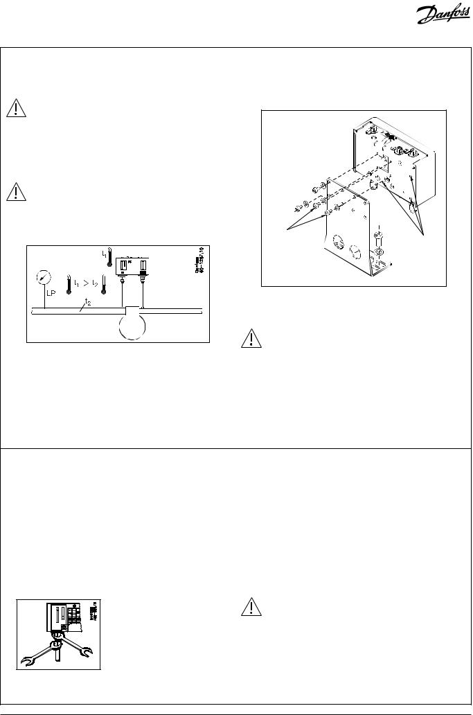
Mount the pressure switch in a position that will allow drainage of liquids away from switch bellows. Pressure connection of the switch must always be located on the top side of the refrigerant line. This reduces the possibility of oil, liquids, or sediment collecting in the bellows, which could cause the switch malfunction.
IMPORTANT:
Ensure the ambient temperature for the dual pressure switch on LP side is higher than the refrigeration line as that will prevent liquid migration and accumulation in the bellows.
Recommended |
mounting position |
Mount the KPU pressure switch on a bracket or on a completely flat surface. Mounting to an uneven surface might cause improper switch operation.
|
1259.11 |
|
|
- |
|
|
Danfoss60 |
|
Screws for |
Mounting holes |
|
bracket mounting |
||
for flat surfaces |
||
|
Use only the mounting holes provided; no other holes are to be added to the switch.
IMPORTANT:
Pressure pulsations in the refrigeration system reduce life time of the bellows and might disturb switch function. Pressure pulsations should always be effectively damped e.g. by connection the pressure switches to the refrigeration system through a capillary tube.
Recommendations for capillary tube and flare connections:
1.Ensure self-draining of the capillary tube to minimize clogging.
2.Coil excess capillary tube into smooth, circular coils (approx. 3 inch diameter). The coiled tube should be securely fastened in order to prevent possible damage due to vibration.
3.Leave a little slack in the capillary tube as it helps to damp mechanical vibrations.
4.Avoid sharp bends as well as re-bending of the capillary tube on the same point as it weakens the material, increasing the risk of crack.
5.Never allow for contact between the capillary tube and sharp or abrasive objects as during vibrations the tube could be damaged due to friction.
6.Purge the piping before connecting pressure switches.
8.Do not over tighten flare nuts as it may damage the threads causing leaks.
9.Protect the capillary tube from damage caused by vibrations from compressor:
–when the switch unit is mounted directly on the compressor, the capillary must be secured to the compressor so that everything vibrates as a whole.
–when the switch is mounted remote from the compressor, make the pressure connections away from the compressor.
–when the switch is mounted remote from the compressor and the pressure connections have to be on the compressor, then damping coils must be used between the compressor and the pressure switch.
7.Always use two wrenches tightening the flare nut on the pressure switch. One wrench should support the connector while the second wrench is used to tighten the nut.
NOTE:
After installing the pressure switch, evacuate the plant in accordance with applicable EPA and other regulations, to remove air, moisture, and other contaminants.
2 | 520H11521 | DKRCC.PI.CD0.C6.02 |
© Danfoss | DCS (jmn) | 2017.01 |
 Loading...