


 Loading...
Technical Information
PVE Series 4 and PVHC
Electrohydraulic Actuators
www.danfoss.com

Technical Information
PVE Series 4 for PVG 32/100/120 and PVHC
Revision history |
Table of revisions |
|
|
|
|
|
|
|
|
|
Date |
|
Changed |
Rev |
|
|
|
|
|
|
April 2020 |
|
Added note to PVE Control section, updated version number to match online |
0910 |
|
|
|
catalogue |
|
|
|
|
|
|
|
|
|
Changed document number from 'BC00000050' to 'BC152886484010' |
XX |
|
|
|
|
|
|
December 2018 |
|
PVEA tech data update. |
0808 |
|
|
|
|
|
|
June 2018 |
|
edits to PVE Hysteresis and Ripple topic |
0807 |
|
|
|
|
|
|
April 2018 |
|
Safety - minor edits |
0806 |
|
|
|
|
|
|
March 2018 |
|
add to Code numbers - PVE accessories |
0805 |
|
|
|
|
|
|
February 2018 |
|
Removal of line of text from page 23 |
0804 |
|
|
|
|
|
|
2006 - 2017 |
|
Various changes. |
0102-0803 |
|
|
|
|
|
|
May 2005 |
|
First edition. |
0101 |
|
|
|
|
|
2 | © Danfoss | April 2020 |
BC152886484010en-000910 |

Technical Information |
|
PVE Series 4 for PVG 32/100/120 and PVHC |
|
Contents |
|
General Information |
|
List of abbreviations for PVG/PVE............................................................................................................................................... |
5 |
Literature reference for PVG products...................................................................................................................................... |
6 |
Standards for PVE............................................................................................................................................................................. |
7 |
PVE with connector variants......................................................................................................................................................... |
7 |
Warnings.............................................................................................................................................................................................. |
8 |
PVE series 4 introduction............................................................................................................................................................... |
8 |
PVE stands for PVE actuator ......................................................................................................................................................... |
8 |
PVG with PVE structural layout.................................................................................................................................................... |
9 |
Functionality |
|
PVG functionality............................................................................................................................................................................ |
11 |
PVE functionality............................................................................................................................................................................ |
11 |
PVE hydraulic subsystems..................................................................................................................................................... |
11 |
Variant of hydraulic subsystem: PVEA......................................................................................................................... |
12 |
Variant of hydraulic subsystem: PVE with ramp....................................................................................................... |
13 |
Variant of hydraulic subsystem: PVHC......................................................................................................................... |
13 |
Mechanical subsystem............................................................................................................................................................ |
14 |
Electronic subsystem............................................................................................................................................................... |
14 |
Safety |
|
Safety and monitoring................................................................................................................................................................. |
16 |
PVG fault monitoring and reaction.................................................................................................................................... |
16 |
Active fault reaction is activated after 500 ms of error (PVEA: 750 ms). ......................................................... |
16 |
Passive fault reaction is activated after 250 ms of error (PVEA: 750 ms)......................................................... |
16 |
The solenoid valves are disabled when:..................................................................................................................... |
17 |
Spool position feedback (-SP).............................................................................................................................................. |
17 |
Direction indication feedback (-DI).................................................................................................................................... |
18 |
Solenoid disabling function (-NP)....................................................................................................................................... |
18 |
Safety in Application..................................................................................................................................................................... |
19 |
Example of a control system for manlift........................................................................................................................... |
20 |
Examples of wiring block diagram................................................................................................................................ |
21 |
PVE Control |
|
PVE control by voltage................................................................................................................................................................. |
23 |
PLUS+1® Compliant.................................................................................................................................................................. |
24 |
ATEX PVE...................................................................................................................................................................................... |
24 |
PVEU–PVE with fixed control signal range...................................................................................................................... |
24 |
PVE controlled with PWM signal......................................................................................................................................... |
24 |
PVEP control..................................................................................................................................................................................... |
25 |
PVEO................................................................................................................................................................................................... |
26 |
PVE ON/OFF activation........................................................................................................................................................... |
26 |
PVE for float spool.......................................................................................................................................................................... |
26 |
There are two variants of float spool PVBS...................................................................................................................... |
27 |
PVHC control.................................................................................................................................................................................... |
28 |
PVE Hysteresis and Ripple........................................................................................................................................................... |
29 |
Example of PVE use....................................................................................................................................................................... |
29 |
Technical Data |
|
PVE operating parameters ......................................................................................................................................................... |
32 |
PVHC control specification......................................................................................................................................................... |
33 |
PVEO and PVEM control specification.................................................................................................................................... |
33 |
PVEA, PVEH, PVES and PVEU control specification ........................................................................................................... |
34 |
PVEP Technical Data...................................................................................................................................................................... |
35 |
PVE dimensions for PVG 32 and PVG 100.............................................................................................................................. |
35 |
PVE dimensions for PVG 120...................................................................................................................................................... |
37 |
PVEO pinout..................................................................................................................................................................................... |
39 |
PVEO connection............................................................................................................................................................................ |
40 |
PVE standard connection data / pinout ................................................................................................................................ |
40 |
PVE standard connections..................................................................................................................................................... |
41 |
Standard PVE with DI............................................................................................................................................................... |
42 |
© Danfoss | April 2020 |
BC152886484010en-000910 | 3 |

Technical Information |
|
PVE Series 4 for PVG 32/100/120 and PVHC |
|
Contents |
|
Standard PVE with SP.............................................................................................................................................................. |
42 |
Standard PVE with NP............................................................................................................................................................. |
43 |
PVHC connection........................................................................................................................................................................... |
43 |
PVE with separate float pin......................................................................................................................................................... |
44 |
PVEP with controled PWM.......................................................................................................................................................... |
44 |
Warnings |
|
PVE warnings................................................................................................................................................................................... |
46 |
Code Numbers |
|
PVE code numbers for PVG 32 and PVG 100 use................................................................................................................ |
47 |
PVE code numbers for use on PVG 120.................................................................................................................................. |
48 |
PVE accessories............................................................................................................................................................................... |
49 |
Connector code numbers at other suppliers ...................................................................................................................... |
50 |
PVED-CC code numbers for use on PVG 32 and PVG 100............................................................................................... |
50 |
4 | © Danfoss | April 2020 |
BC152886484010en-000910 |

Technical Information
PVE Series 4 for PVG 32/100/120 and PVHC
General Information
List of abbreviations for PVG/PVE
Abbreviation |
Description |
|
|
ASIC |
Application Specific Integrated Circuit - the part of the PVE where spool position is controled to |
|
follow setpoint |
|
|
ATEX |
Certificated for use in explosive environment |
|
|
AVC |
Auxillery Valve Comand - ISOBUS/J1939 standard signal for valve control |
|
|
AVCTO |
Auxillery Valve Comand Time Out - Fault monitoring setting |
|
|
AVEF |
Auxillery Valve Estimated Flow - ISOBUS/J1939 standard signal for valve feedback |
|
|
CAN |
Controller Area Network - Communication method used by PVED |
|
|
CLC |
Closed Loop Circuit |
|
|
CRC |
Cyclic Redundancy Check - Method for ensuring validity of data. |
|
|
-DI |
PVE with Direction Indication |
|
|
DM1 |
Diagnostic Message 1 - J1939 message informing about present fault |
|
|
DM2 |
Diagnostic Message 2 - J1939 message informing about fault history |
|
|
DM3 |
Diagnostic Message 3 - J1939 message clearing fault history |
|
|
DSM |
Device State Machine. Deterministic description of system process |
|
|
ECU |
Electronic Control Unit |
|
|
EH |
Electrohydraulic |
|
|
-F |
PVE for Float spool. Two variants: 4 pin with float at 75%. 6 pin with separate float. |
|
|
FMEA |
Failure Mode Effect Analysis |
|
|
ISOBUS |
Communication standard for CAN |
|
|
J1939 |
Communication standard for CAN |
|
|
LED |
Light Emitting Diode |
|
|
LS |
Load Sensing |
|
|
LVDT |
Linear Variable Differential Transducer - Position sensor |
|
|
NC |
Normally Closed solenoid valve in PVE |
|
|
NC-H |
Normally Closed standard solenoid valve in PVEH |
|
|
NC-S |
Normally Closed solenoid valve Super in PVES |
|
|
NO |
Normally Open solenoid valve in PVE |
|
|
PLC |
Programmable Logical Circuit |
|
|
PLUS+1® |
Trademark for Danfoss controllers and programming tool |
POST |
Power On Self Test. Boot up evaluation for PVED |
|
|
Pp |
Pilot Pressure. The oil gallery for PVE actuation |
|
|
PVB |
Proportional Valve Basic module - valve slice |
|
|
PVBS |
Proportional Valve Basic module Spool |
|
|
PVBZ |
Proportional Valve Basic module Zero leakage |
|
|
PVE |
Proportional Valve Electric actuator |
|
|
PVEA |
PVE variant with 2-6 % hysteresis |
|
|
PVED |
PVE variant Digital controlled via CAN communication |
|
|
PVEH |
PVE variant with 4-9% Hysteresis |
|
|
PVEM |
PVE variant with 25-35% hysteresis |
|
|
PVEO |
PVE variant with ON/OFF actuation |
|
|
PVEP |
PVE variant PWM controled |
|
|
PVES |
PVE variant with 0-2% hysteresis |
|
|
PVEU |
PVE variant with US 0-10V |
|
|
PVG |
Proportional multi-section Valve Group |
|
|
PVHC |
PV variant with High Current controlled valve actuator |
|
|
© Danfoss | April 2020 |
BC152886484010en-000910 | 5 |

Technical Information
PVE Series 4 for PVG 32/100/120 and PVHC
General Information
Abbreviation |
Description |
|
|
PVM |
Proportional Valve Manual control with handle |
|
|
PVP |
Proportional Valve Pump side module.Inlet |
|
|
PVS |
Proportional Valve end plate |
|
|
PVSK |
Proportional Valve end plate crane. Inlet module with Spool Control |
|
|
PWM |
Pulse Width Modulation |
|
|
S4 DJ |
Series 4 Digital J1939 service tool software for PVED-CC |
|
|
SAE |
Society Automotive Engineering |
|
|
-R |
PVE with Ramp function |
|
|
-NP |
PVE with solenoid disable in Neutral Position |
|
|
-SP |
PVE with Spool Position feedback |
|
|
uC |
Microcontroller |
|
|
uCSM |
Microcontroller State Machine |
|
|
UDC |
Power supply Direct Current; also called Vbat for battery voltage |
US |
Steering voltage for the PVE control; also called VS |
Literature reference for PVG products
Literature reference
Literature title |
Type |
Order |
|
|
number |
|
|
|
PVG 32 Proportional Valve Group |
Technical Information |
BC152886483 |
|
|
664 |
|
|
|
PVG 100 Proportional Valve Group |
Technical Information |
BC152886483 |
|
|
475 |
|
|
|
PVG 120 Proportional Valve Group |
Technical Information |
BC152886483 |
|
|
344 |
|
|
|
PVG 32 Metric ports |
Technical Information |
BC152886484 |
|
|
163 |
|
|
|
PVE Series 7 |
Technical Information |
BC173386484 |
|
|
192 |
|
|
|
PVE Series 4 |
Technical Information |
BC152886484 |
|
|
010 |
|
|
|
PVED-CC Electro-hydraulic actuator |
Technical Information |
520L0665 |
|
|
|
PVED-CX Electro-hydraulic actuator |
Technical Information |
BC152886483 |
|
|
682 |
|
|
|
PVE-CI |
Technical Information |
BC163786485 |
|
|
206 |
|
|
|
Basic module for PVBZ |
Technical Information |
BC152886484 |
|
|
167 |
|
|
|
PVSK module with integrated diverter valve and P-disconnect function |
Technical Information |
BC152886484 |
|
|
133 |
|
|
|
PVPV / PVPM pump side module |
Technical Information |
BC152886484 |
|
|
316 |
|
|
|
Combination module PVGI |
Technical Information |
BC152886483 |
|
|
392 |
|
|
|
PVSP/M Priority module |
Technical Information |
BC152886484 |
|
|
066 |
|
|
|
Hitch Control |
System Description |
AB152886482 |
|
|
484 |
|
|
|
|
User Manual |
11033753 |
|
|
|
6 | © Danfoss | April 2020 |
BC152886484010en-000910 |

Technical Information
PVE Series 4 for PVG 32/100/120 and PVHC
General Information
Literature reference (continued)
Literature title |
Type |
Order |
|
|
number |
|
|
|
PVBZ |
Data Sheet |
AI1528864823 |
|
|
57 |
|
|
|
PVBZ-HS |
Data Sheet |
AI1528864822 |
|
|
19 |
|
|
|
PVBZ-HD |
Data Sheet |
AI1528864821 |
|
|
40 |
|
|
|
MC024-010 and MC024-012 Controllers |
Data Sheet |
AI1528864807 |
|
|
85 |
|
|
|
Standards for PVE
•International Organization for Standardization ISO 13766 Earth moving machinery - Electromagnetic compatibility.
•EN 50014:1997 +A1, A2: 1999
•EN 50028: 1987. For ATEX approved PVE
‒IEC EN 61508
‒ISO 12100-1 / 14121
‒EN 13849 (Safety related requirements for control systems)
‒Machinery Directive 2006/42/EC” (1st Edition December 2009)
PVE with connector variants
Hirschmann/DIN variant |
DEUTSCH variant |
AMP variant |
© Danfoss | April 2020 |
BC152886484010en-000910 | 7 |
Technical Information
PVE Series 4 for PVG 32/100/120 and PVHC
General Information
Warnings
Before implementing actuators in any application, read all warnings. Warnings are listed next to the most relevant section and repeated in the chapter PVE-EX warnings.
Do not regard the warnings as a full list of potential risks. Depending on the application and use, other potential risks can occur.
W Warning
All brands and all types of directional control or proportional valves, which are used in many different operation conditions and applications, can fail and cause serious damage.
You must perform a risk assessment. The machine builder/system integrator alone is responsible for making the final selection of the products and assuring that all performance, safety and warning requirements of the application are met.
The process for choosing the control system and safety levels is governed by the Machinery Directive 2006/42/EC and EU harmonized standard EN 13849 (Safety related requirements for control systems).
PVE series 4 introduction
PVE Series 4 is the common name for the Danfoss PVG electrical actuator. This technical information covers our voltage controlled PVE and our current controlled PVHC actuator. For the PVHC please see in the PVHC sectionl. The digital actuators PVED-CC and PVED-CX are covered in their special technical information.
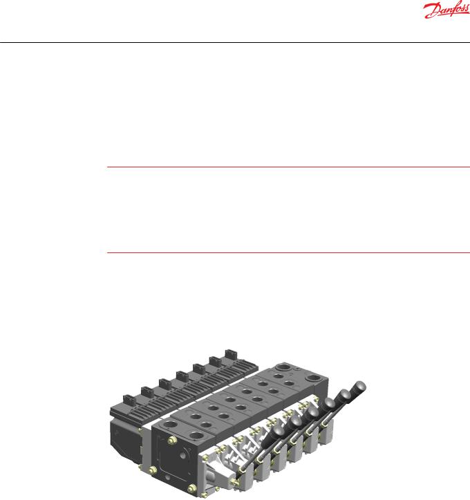
PVE controlled PVG with PVSK
PVE stands for PVE actuator
The Danfoss PVE is built on more than thirty years experience of electrical valve control and is the perfect fit for our high performance proportional valves PVG 32, PVG 100 and PVG 120, as it is for our EH steering.
All our products are developed in close cooperation with system manufacturers from the mobile hydraulic market. That is the reason for our high performance in all market segments
The PVE can be controlled from a switch, a joystick, a PLC, a computer or a Danfoss PLUS+1® microcontroller. The PVE is available in multiple variants. A short list here just gives the main variations.
Available PVE variants
|
Actuation |
On/Off |
|
|
|
|
|
Proportional - Closed loop controlled |
|
|
|
|
|
Proportional - Direct control |
|
|
|
|
|
|
8 | © Danfoss | April 2020 |
BC152886484010en-000910 |

Technical Information
PVE Series 4 for PVG 32/100/120 and PVHC
General Information
Available PVE variants (continued)
Control signal |
Voltage |
|
|
|
PWM |
|
|
|
Current (PVHC) |
|
|
Precision |
Standard precision |
|
|
|
High precision |
|
|
|
Super high precision |
|
|
Feedback |
Spool position |
|
|
|
Direction indicator |
|
|
|
Error |
|
|
|
None |
|
|
Connectors |
DEUTSCH |
|
|
|
AMP |
|
|
|
DIN/Hirschmann |
|
|
Fault detection and reaction |
Active |
|
|
|
Passive |
|
|
|
None |
|
|
Power supply |
11 V – 32 V multi-voltage |
|
|
|
12 V |
|
|
|
24 V |
|
|
PVG with PVE structural layout
The PVG is a sectional spool valve stack with up to 12 individually controlled proportional valves. The PVG with the PVE can be operated as single valves or several valves in cooperation. The oil flow out of the work section (A- or B-port) can be controlled by a combination of the following:
•PVE controlling the spool position using pilot oil pressure.
•A handle (PVM) in mechanical interface with the spool.
PVG 32 structural lay-out with naming
Legend:
A – A-port
B – B-port
C – PVS end plate
D – PVB basic module
E – Connector Pin
T – Tank port
P – Work flow
© Danfoss | April 2020 |
BC152886484010en-000910 | 9 |
Technical Information
PVE Series 4 for PVG 32/100/120 and PVHC
General Information
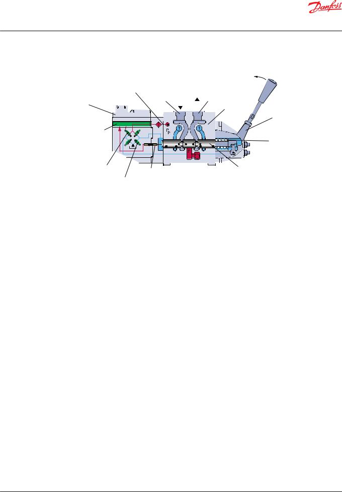
Valve section - standard mounted - seen from PVP with naming
P -> A
|
|
Pilot oil supply |
|
|
|
||||
PVE |
|
|
|
|
B port |
|
Oil |
A port |
|
|
|
|
|
||||||
|
|
|
|
|
|
PVB |
|||
|
|
|
|
|
|
|
|
|
|
|
|
|
|
|
|
|
|
|
|
|
|
PVM |
Electronics |
|
|
|
|
Neutral spring |
NC Solenoid valve |
<- Retract towards PVE |
PVBS |
LVDT |
|
|
Extend away from PVE -> |
|
|
NO solenoid valve |
|
|
|
|
V310072.A |
Oil out of A-port → PVM pushed towards PVB → retract → LVDT moves into PVE
10 | © Danfoss | April 2020 |
BC152886484010en-000910 |
Technical Information
PVE Series 4 for PVG 32/100/120 and PVHC
Functionality
PVG functionality
This chapter will give an overview of the PVG and its functionality.
Valve section with naming - standard mounted - seen from PVP
P -> A
|
|
Pilot oil supply |
|
|
|
||||
PVE |
|
|
|
|
B port |
|
Oil |
A port |
|
|
|
|
|
||||||
|
|
|
|
|
|
PVB |
|||
|
|
|
|
|
|
|
|
|
|
|
|
|
|
|
|
|
|
|
|
|
|
PVM |
Electronics |
|
|
|
|
Neutral spring |
NC Solenoid valve |
<- Retract towards PVE |
PVBS |
LVDT |
|
|
Extend away from PVE -> |
|
|
NO solenoid valve |
|
|
|
|
V310072.A |
The PVG valve distributes oil from pump flow to a particular work function in the application via a specific valve section. This is done by moving the spool (PVBS).
Depending on the choice of components the oil work flow enters the PVG through the PVP (proportional valve pump side module) or the PVSK (proportional valve end plate for crane) and enters the PVB (proportional valve basic module) via the P gallery and leaves through the T gallery.
In the figure above you see a valve section seen from PVP towards PVSK with the PVM and PVE standard mounted. PVM and PVE can in general be interchanged, that is called option mounted.
With the spool in neutral, where it is kept by the neutral spring, the connection to the application via ports is blocked.
Moving the spool towards the PVE, as in figure 4, opens a connection between P and A and also between B and T. This is done by either pushing the PVM or sending a retract command to PVED. The PVED move the spool by letting Pilot Oil Pressure (Pp) push on the right end of the PVBS and releasing pressure from the left end. For details on PVG please see relevant technical information.
Any PVG with PVM can be operated by PVM alone, independent of a power supply. Any PVG with can monitor PVBS if power and communication conditions are present.
PVE functionality
This section has focus on how the PVE works and interacts. The description here is general and variant specific descriptions will all refer to this.
The PVE is an electro mechanical device, meaning that functionality is depending on mechanical, hydraulic, electrical and control conditions given by PVE, PVG, application and vehicle. The result of this is that implementing operation and safety conditions also must include vehicle specific considerations.
PVE hydraulic subsystems
The hydraulic subsystem is used for moving the spool and thereby open the valve for work flow.
© Danfoss | April 2020 |
BC152886484010en-000910 | 11 |
Technical Information
PVE Series 4 for PVG 32/100/120 and PVHC
Functionality
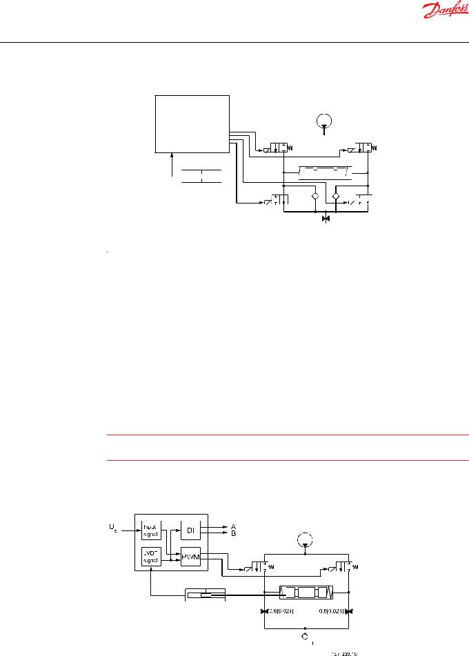
Pilot oil diagram
Set point 
Electronics |
Pp |
NC1 
NC3


 Spool
Spool
LVDT


 NO4
NO4
NO2
1.0 [0.039]
Tank 

V310073.A
The hydraulic subsystem moves the spool and thereby opens the valve for work flow. The heart in the hydraulic subsystem is the solenoid valve bridge which controls the Pilot Pressure (Pp) on spool ends. It consist of four poppet valves, the two upper are normally closed (NC) and the two lower are normally open (NO).
The Pp will work against the PVBS neutral spring when the spool is moved out of blocked (neutral) and together with the spring when going in blocked. This combined with a larger opening in the NO than in the NC will give a faster movement towards blocked than out of blocked.
When the PVE is powered the solenoids are all put in closed state. To move the PVBS to the right NC1 and NO4 are opened and NC3 and NO4 are kept closed.
The activation of the solenoid valves represents oil consumption and thereby also a pressure drop in the pilot oil gallery. By simultaneous use of multiple PVE the Pp can fall and result in performance problems.
The two check valves next to the NO are anti-cavitation valves. The orifice to tank reduces tank pressure spikes and can also be used for ramp function.
W Warning
Obstacles for the Pilot oil pressure (Pp) can have direct influence on spool control. Reduced Pp will limit spool control. Too high Pp can harm the PVE.
Variant of hydraulic subsystem: PVEA
Hydraulic variant: PVEA
|
|
|
|
|
|
|
|
|
|
|
|
|
|
|
|
|
|
|
|
12 | © Danfoss | April 2020 |
|
|
BC152886484010en-000910 |

Technical Information
PVE Series 4 for PVG 32/100/120 and PVHC
Functionality
NO2 and NO4 are replaced with orifices.
W Warning
PVEA is not for use on PVG 100.
Variant of hydraulic subsystem: PVE with ramp
Hydraulic subsystem variant: PVE with ramp
Tank orifice has smaller diameter.
With electrical proportional actuation, the main spool position is adjusted so that its position corresponds to an electrical control signal.
The control signal is converted into a hydraulic pressure signal that moves the main spool in the PVG. This is done by means of two proportional pressure-reducing valves. The electrical actuator can be controlled either by a current amplifier card, or directly from a programmable microcontroller.
For more information see these technical informations:
•PVG 32 Proportional Valve Groups BC152886483664,
•PVG 100 Proportional Valve Groups BC152886483475 and
•PVG 120 Proportional Valve Groups BC152886483344.
Variant of hydraulic subsystem: PVHC
The PVHC does not work as a PVE and does not have transducer, anti cavitation nor protection against tank pressure spikes. It is necessary to use the PVHC in combination with 25 bar [362.6 psi] pilot pressure, and standard FC spools fitted for hydraulic actuation. Because of the 25 bar pilot pressure, it is not possible to combine PVHC with PVE on a PVG.
Hydraulic subsystem variant: PVHC
With electrical proportional actuation, the main spool position is adjusted so that its position corresponds to an electrical control signal. The control signal is converted into a hydraulic pressure signal that moves the main spool in the PVG. This is done by means of two proportional pressure-reducing valves. The
© Danfoss | April 2020 |
BC152886484010en-000910 | 13 |
Technical Information
PVE Series 4 for PVG 32/100/120 and PVHC
Functionality
electrical actuator can be controlled either by a current amplifier card, or directly from a programmable microcontroller.
For more information see these technical informations:
•PVG 32 Proportional Valve Groups BC152886483664,
•PVG 100 Proportional Valve Groups BC152886483475 and
•PVG 120 Proportional Valve Groups BC152886483344.
Mechanical subsystem
The mechanical subsystem gives interface to valve and control system and provides protection to hydraulic and electrical/electronic subsystem. The LVDT, not used on all variants, gives feed back to electronics on spool position. The LVDT is calibrated in production and recalibration should only be done in special cases. The standard PVE has an aluminum block for distributing pilot oil. PVE with anodized block are available.
The connector gives the electrical interface to power and control system. Danfoss have a variety of connectors. We know that tradition and the aspects of serviceability are important when our customers choose. We have chosen the Deutsch connector as our main solution. The quality of wiring has direct influence on water integrity and signal quality therefore disturbance or changes in cabling can influence safety and performance.
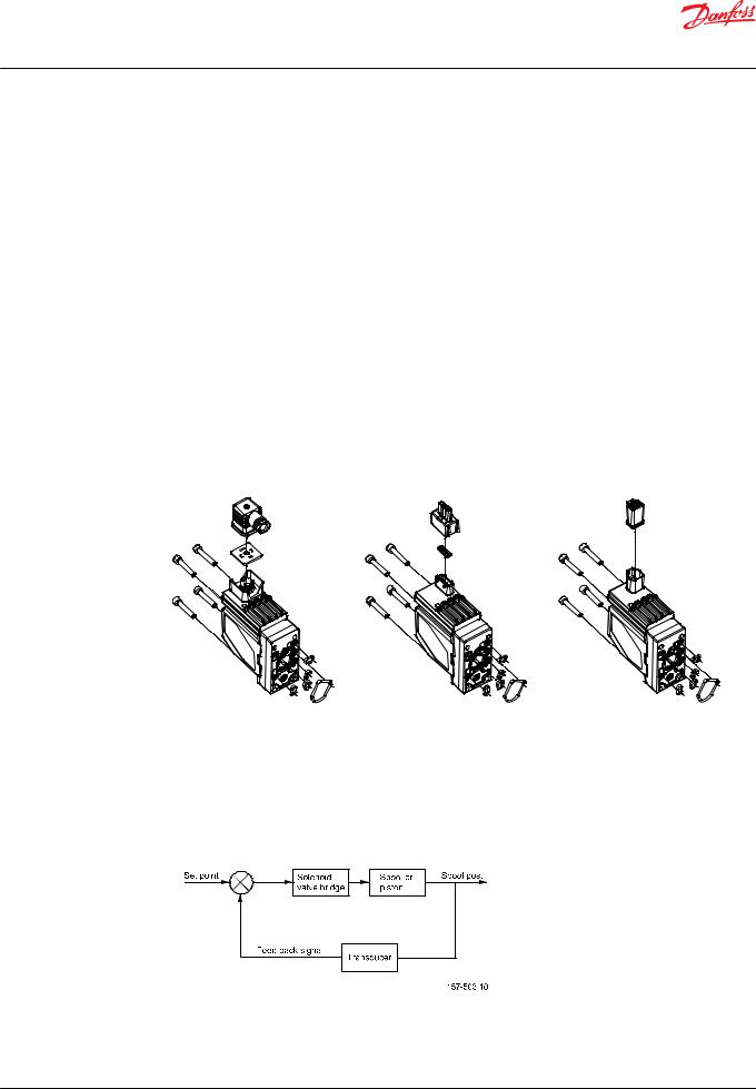
PVE connectors: Hirschmann/DIN, AMP and Deutsch
V310 390B
Electronic subsystem
The PVE (A/H/M/S/U) control signal is a low current voltage, a PWM can also be used. The PVEP has buildin a PWM evaluation and cannot be controlled by proportional voltage. The control signal is referred to as US.
Function blocks for electronics
The PVE features Closed Loop Control (CLC). This is made possible by on board electronics and an integrated feedback transducer that measures spool movement. The integrated electronics compensate for flow forces on the spool, internal leakage, changes in oil viscosity, pilot pressure, etc. This results in lower hysteresis and better resolution.
14 | © Danfoss | April 2020 |
BC152886484010en-000910 |

Technical Information
PVE Series 4 for PVG 32/100/120 and PVHC
Functionality
In principle the set-point determines the level of pilot pressure which moves the main spool. The position of the main spool is sensed in the LVDT which generates an electric feed-back signal registered by the electronics. The variation between the set-point signal and feed-back signal actuates the solenoid valves. The solenoid valves are actuated so that hydraulic pilot pressure drives the main spool into the correct position.
The LVDT (Linear Variable Differential Transducer) is an inductive transducer with very high resolution. When the LVDT is moved by the main spool a voltage is induced proportional to the spool position. The use of LVDT gives contact-free connection between mechanics and electronics. This means an extra long lifetime and no limitation as regards the type of hydraulic fluid used.
The PVEO and PVHC do not have embedded control electronics and do not support closed loop control.
© Danfoss | April 2020 |
BC152886484010en-000910 | 15 |

Technical Information
PVE Series 4 for PVG 32/100/120 and PVHC
Safety
Safety and monitoring
The choice of PVE also decides the level of feedback and safety. PVE are available with fault monitoring, spool direction indication, spool position feedback and separate float control.
The fault monitoring is available in PVEA/H/S/P/U and is a utilization of the ASIC.
Direction Indication is available in PVEO/A/H and they are dual powered PVE where separate pins give an active feedback for spool movement.
Spool position is available in PVES and is a precise feedback on a separate pin for actual spool position. The separate float control is a protection against unintended float activation.
The PVEM, PVEO and PVHC do not have fault monitoring.
PVG fault monitoring and reaction
The fault monitoring system is available in two versions:
•Active fault monitoring provides a warning signal and deactivates the solenoid valves. A reboot of the PVE is required to reactivate.
•Passive fault monitoring provides a warning signal only. A reboot is not required.
Both active and passive fault monitoring systems are triggered by the same four main events:
1.Control signal monitoring
The Control signal voltage (US) is continuously monitored. The permissible range is between 15% and 85% of the supply voltage. Outside this range the section will switch into an error state. A disconnected US pin (floating) is recognized as neutral set point.
2.Transducer supervision
The internal LVDT wires are monitored. If the signals are interrupted or short-circuited, the PVE will switch into an error state.
3.Supervision of spool position
The actual position must always correspond to the demanded position (US). If the actual spool position is further out from neutral than the demanded spool position or in opposite direction, the PVE will switch into an error state. Spool position closer to neutral and in same direction will not cause an error state. The situation is considered “in control”.
4.Float monitoring
Float must be entered or left within a time limit. On the six pin float PVE too high delay will cause an error state. The float Time Outs has own thresholds. Only relevant for the six pin PVEH-F.
Active fault reaction is activated after 500 ms of error (PVEA: 750 ms).
•The solenoid valve bridge is disabled and the PVBS is released to spring control
•The error pin is powered*
•The LED change color
•The state is memorized and continues until PVE reboot
Passive fault reaction is activated after 250 ms of error (PVEA: 750 ms)
•The solenoid valve bridge is NOT disabled and the PVBS is NOT released
•The error pin is powered ( for PVE with direction indication both DI pins goes low by fault.)
•The LED change color
•The state is active for minimum 100 ms and is reset when error disappears
16 | © Danfoss | April 2020 |
BC152886484010en-000910 |
Loading...