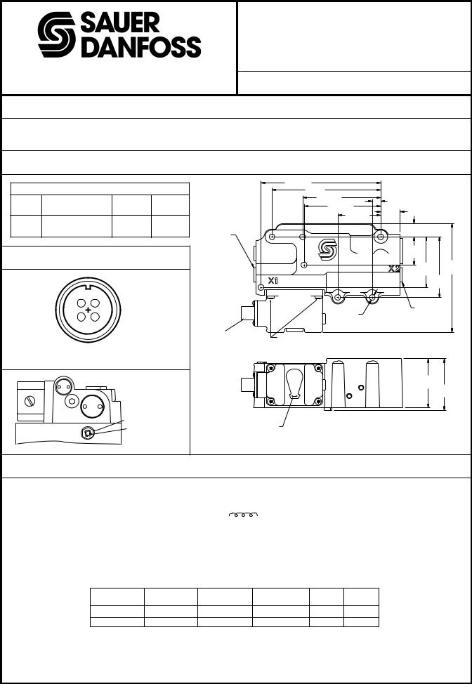
Danfoss KVMB12501 Installation guide

Unit Specification
KVMB12501
Electrical Displacement Control
3500 Annapolis Lane North, Minneapolis, MN 55447 |
|
|
Telephone: (763) 509-2084 Telefax: (763) 559-0108 |
ISSUE: 2 |
DATE: June 1995 |
GENERAL DESCRIPTION
This device is an electrohydraulic pump stroke control which uses mechanical feedback to establish closed loop control of the swashplate angle of Sauer-Danfoss Series 42 PV.
DIMENSIONS |
|
|
|
|
|
|
|
|
|
|
|
|
|
|
140,2 (5.52) |
|
|
Pump Phasing With EDC Manual Operator (MO) |
|
|
127 (5.0) |
|
|
|||
Pump |
MO |
|
Control Port |
Pump Flow |
|
91,2 (3.59) |
10 (0.39) |
|
|
|
89,7 (3.53) |
|
|||||
Rotation |
Rotation |
|
Goes High |
Out Port |
|
22,5 |
|
|
|
|
50,2 (1.98) |
|
|||||
|
Towards Connector |
|
|
|
(0.89) |
|
||
CW |
X2 |
A |
|
|
16 |
|
||
CCW |
Towards Connector |
X2 |
B |
|
|
|
||
SAE CONTROL |
|
(0.63) |
|
|||||
|
|
|
|
|
|
|
||
|
|
|
|
|
|
|
|
|
|
|
|
|
|
PORT FITTING |
|
|
|
|
|
|
|
|
X1 |
|
33,6 |
|
ELECTRICAL CONNECTION |
|
|
(1.32) |
|
||||
|
|
60,2 |
129,2 |
|||||
|
|
|
|
|
|
|
||
|
|
|
|
|
|
|
(5.09) |
|
|
|
|
|
|
|
|
(2.37) |
|
|
|
|
|
|
|
|
|
|
|
|
|
|
|
|
|
72,2 |
|
|
|
|
|
|
|
|
(2.84) |
|
|
D |
A |
|
|
|
|
SAE CONTROL |
|
|
|
|
|
|
|
|
||
|
C |
B |
|
|
|
Ø6,7 (7) |
PORT FITTING |
|
|
|
|
|
(Ø.26) |
X2 |
|
||
|
|
|
|
|
|
|
||
|
|
|
|
|
MS |
|
|
|
|
|
|
|
1276 |
CONNECTOR |
CAUTION: |
|
|
|
|
|
|
(4 PIN) |
DO NOT REMOVE |
|
|
|
|
° |
MS Mating Connector. Part |
|
|
||||
|
|
COVER SCREWS |
|
|
||||
Pin Orientation of 4-pin, 90 |
|
|
|
|
||||
No. MS3108E-14S-2S (Sauer-Danfoss Kit No. K08106). |
|
|
|
|
||||
|
|
|
|
|
|
|
58 |
|
|
|
|
|
|
|
|
(2.28) |
61,2 |
|
|
|
|
|
|
|
|
(2.41) |
|
EDC |
|
17 mm LOCK NUT |
|
|
|
|
|
|
|
|
|
|
|
|
||
PUMP |
|
|
5 mm |
|
MANUAL OPERATOR |
|
1759 |
|
|
|
|
|
|
|
|||
|
|
|
NEUTRAL ADJUST |
|
|
|
|
|
|
|
|
|
1752 |
Dimensions of the KVMB12501 in Millimeters (Inches). |
|
||
ELECTRICAL CHARACTERISTICS
INPUT SHAFT ROTATION VS. TERMINAL CONNECTION VS. OUTPUT FLOW
|
Input |
|
A |
B |
|
Produces |
|
|
||
|
|
|
|
|
||||||
|
Shaft |
|
|
Flow Out |
|
|
||||
|
|
|
|
|
|
|
||||
|
Rotation |
|
|
|
|
Of Port |
|
|
||
|
+ phasing to terminals |
|
|
|||||||
|
|
|
|
|
|
|
||||
|
|
|
|
|
|
|
|
|
|
|
|
Clockwise |
A |
B |
|
A |
|
B |
|
|
|
|
Counter |
A |
B |
|
B |
|
A |
|
|
|
|
Clockwise |
|
|
|
|
|||||
|
|
|
|
|
|
|
|
|
|
|
S t a r t |
Full Stroke |
S t a r t |
|
Full Stroke |
Coil Ω |
Coil Ω |
||||
Current (mA) |
Current (mA) |
Voltage (Vdc) |
Voltage (Vdc) |
75 °F |
2 2 0 °F |
|||||
±4.5 - 5.5 |
±17 - 19 |
±2.9 - 3.6 |
|
±11 - 12.3 |
|
650 |
|
|||
±4.5 - 5.5 |
±17 - 19 |
±3.8 - 4.7 |
|
±14.5 - 16.1 |
|
|
|
850 |
||
MAXIMUM CONTINUOUS VOLTAGE @ 93.9°C (200°F): 24 Vdc.
The EDC is designed to be controlled from a dc current source or voltage source. Pulse width modulation (PWM) is not required. But if a PWM signal is used, it is preferred to avoid a carrier frequency < 200 Hz. Do not use a pulse current of more than 120% of that required for full output.
K18620 UNIT SPEC
1 OF 2
©Copyright 2001, Sauer-Danfoss (US) Company. All rights reserved. Contents subject to change.
 Loading...