


Danfoss PAHT G 20, PAHT G 25, PAHT G32, PAHT G 50, PAHT G 63 Installation guide
...
Instruction
PAHT G pumps
PAHT G 20/25/32 and
PAHT G 50/63/70/80/90
hpp.danfoss.com

|
|
|
|
Instruction |
Pump instruction PAHT G 20-32 and PAHT G 50-90 |
|
|
|
|
|
|
Table of Contents |
1. |
Identification . . . . . . . . . . . . . . . . . . . . . . . . . . . . . . . . . . . . . .3 |
2. System design . . . . . . . . . . . . . . . . . . . . . . . . . . . . . . . . . . . . . 3
2.1Closed water hydraulic systems, water recirculated . . . . . . . . . . . . . . . . . . . 3
2.2 |
Closed-system design . . . . . . . . . . . . . . . . . . . . . . . . . . . . . . . |
. |
. |
3 |
2.3 |
Open-ended systems, water supply from tank . . . . . . . . . . . . . . . . . . . |
. |
. |
4 |
2.4 |
Open-ended systems with direct water supply . . . . . . . . . . . . . . . . . . . |
. |
. |
4 |
2.5 |
Open-system design . . . . . . . . . . . . . . . . . . . . . . . . . . . . . . . . . . 4 |
||
2.6 |
guidelines for calculation of pressure losses . . . . . . . . . . . . . . . . . . . . |
. |
.6 |
3. |
Building up the pump unit . . . . . . . . . . . . . . . . . . . . . . . . . . . . . . . 6 |
||
3.1 |
Mounting . . . . . . . . . . . . . . . . . . . . . . . . . . . . . . . . . . . . . . . 6 |
||
3.2 |
Direction of rotation . . . . . . . . . . . . . . . . . . . . . . . . . . . . . . . . |
. |
.7 |
3.3 |
Orientation . . . . . . . . . . . . . . . . . . . . . . . . . . . . . . . . . . . . . |
. |
.7 |
3.4Protection from too high system pressures . . . . . . . . . . . . . . . . . . . . . . . 7
3.5Connections . . . . . . . . . . . . . . . . . . . . . . . . . . . . . . . . . . . . . . 8
3.5.1 |
PAHT G 20-32 . |
. . . . . . . . . . . . |
. . . |
. . . . . . |
. . . . . . |
. . |
. . . . . |
. |
. |
.8 |
3.5.2 |
PAHT G 50-90 |
. . . . . . . . . . . . |
. . . |
. . . . . . . |
. . . . . |
. . |
. . . . . |
. |
. |
. 8 |
4. |
Initial start-up |
. . . . . . . . . . . . . . . . . . . . . . . . . . . . . . . . . . . . . 9 |
||||||||
5. |
Operation . . . . . . . . . . . . . . . . . . . . . . . . . . . . . . . . . . . . . . . 9 |
|||||||||
5.1 |
Water quality . . . . . . . . . . . . . . . . . . . . . . . . . . . . . . . . . . . . . .9 |
|||||||||
5.2 |
Temperature . . . . . . . . . . . . . . . . . . . . . . . . . . . . . . . . . . . . . .9 |
|||||||||
5.3 |
Pressure . . . |
. . . . . . . . . . . . |
. . . |
. . . . . . . |
. . . . . |
. . |
. . . . . |
. |
. |
. 9 |
5.4 |
Dry running . |
. . . . . . . . . . . . |
. . . |
. . . . . . . |
. . . . . |
. . |
. . . . . |
. |
. |
.10 |
5.5Disconnection . . . . . . . . . . . . . . . . . . . . . . . . . . . . . . . . . . . . .10
5.6 |
Storage . . . . . . . . . . . . . . . . . . . . . . . . . . . . . . . . . . . . . . . .10 |
5.6.1Water hydraulic systems, water recirculated . . . . . . . . . . . . . . . . . . . . . . 10
5.6.2Open-ended systems with water supply from tank. . . . . . . . . . . . . . . . . . . .10
5.6.3 Open-ended systems with direct water supply. . . . . . . . . . . . . . . . . . . . . .10
6. |
Service . . . . . . . . . . . . . . . . . . . . . . . . . . . . . . . . . . . . . . . . 10 |
||||||||||||||
7. |
Recommended service intervals . . . . . . . . . . . . . . . . . . . . . . |
. |
. |
. |
. . . 11 |
||||||||||
7.1 |
General information . . . . . . . . . . . . . . . . . . . . . . . . . . . . |
. |
. |
. |
. . .11 |
||||||||||
7.2 |
Inspection of pump parts . . . . . . . . . . . . |
. . |
. |
. . . |
. . |
. . . |
. |
. . . . . |
. |
. |
11 |
||||
7.3 |
How to inspect the pump . . . . . . . . . . . . |
. . |
. |
. . . |
. . |
. . . |
. |
. . . . . |
. |
. |
11 |
||||
2 |
180R9381 | AN077186502937en-000401 | Instruction PAHT G 20-90 | 08.2020 |
|
|
|
|
Instruction |
Pump instruction PAHT G 20-32 and PAHT G 50-90 |
|
|
|
|
|
|
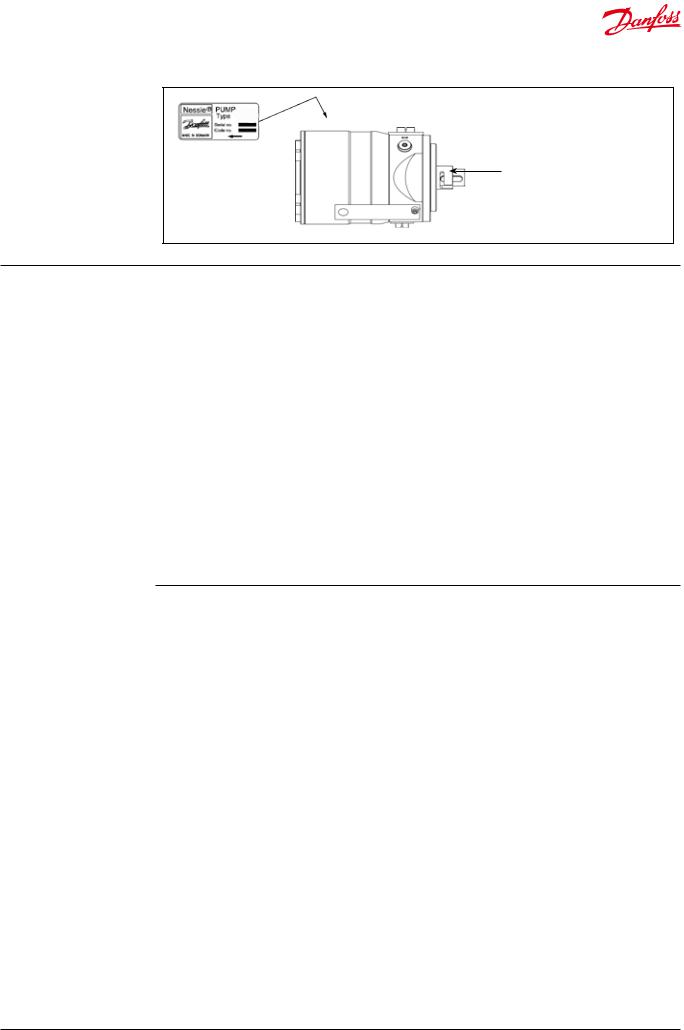
1.Identification
PAHT G
Protective cap must be removed and thrown away before usage.
2. System design |
Systems can be either: |
|
|
• |
Water hydraulic systems, in which the water |
|
|
is recirculated back to tank. |
|
• |
Open-ended systems with water supply |
|
|
from a tank. |
|
• |
Open-ended systems with direct water- |
|
|
supply (boosted pressure). |
The design of the system must ensure that selfemptying of the pump during standstill is avoided.
The minimum boost pressure is 2 barg (29 psig) and the maximum peak pressure is 20 barg (290 psig). The recommended normal boost pressure is 2-6 barg (29-87 psig) (3-7 barg [43.5-101.5 psig] abs).
If it is unknown what the peak inlet pressure can be, then there should be a 15 barg (218 psig) safety relief valve on the inlet side of the pump.
Note: All mentioned pressures refer to measures in the respective pump gauge ports.
The inlet pressure of the pump must never exceed the outlet pressure. This may typically occur in boosted or open-ended systems with supply direct from the tap and where a bypass valve is activated.
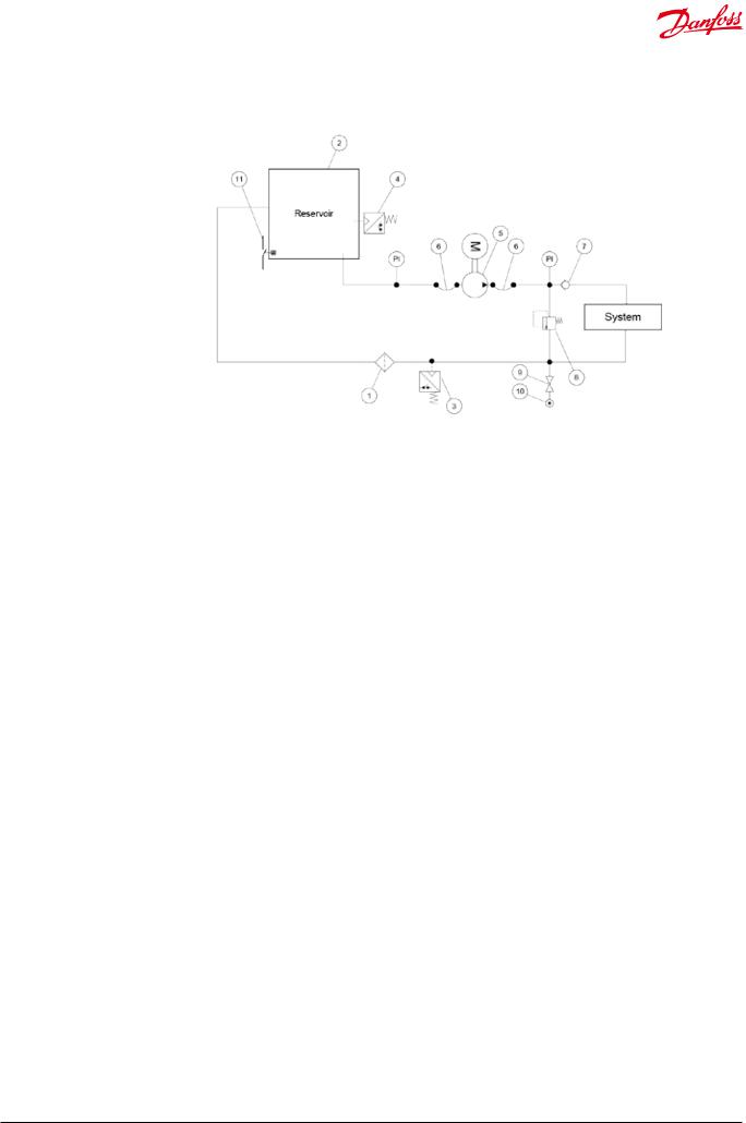
2.1Closed water hydraulic systems, water
recirculated
(The numbers 1- 3 refer to the drawing below ). In order to eliminate the risk of cavitation, always ensure a minimum inlet pressure of 0 barg
(0 psig) (1 barg [14.5 psig] abs) by observing the following guidelines:
2.2 Closed-system design
AInlet line:
Dimension the inlet line to obtain minimum pressure loss (large flow, minimum pipe length, minimum number of bends/ connections, and fittings with small pressure losses).
BInlet filter:
Install the inlet filter (1) in front of the tank
(2).Place the tank above pump and pump inlet. Please consult the Danfoss filter data sheet for guidance on how to select the right filter.
CMonitoring pressure switch:
Install the monitoring pressure switch (3) in front of the filter (1). Set the maximum inlet pressure to 2 barg (29.0 psig). The monitoring pressure switch will stop the pump (5) if inlet pressure is higher than 2 barg
(29.0 psig), indicating that the filter element must be changed.
DMonitoring temperature switch:
Install the monitoring temperature switch
(4)in the tank. Set the temperature value according to technical data, item 4. The monitoring temperature stops the pump if inlet temperature is higher than the set value.
EHoses:
Always use flexible hoses (6) to minimize vibrations and noise.
FInlet pressure:
In order to eliminate the risk of cavitation and other pump damage, pump inlet pressure must be maintained according to specifications described in item 4, technical data.
GNon-return valve (7):
Should be installed after the outlet to prevent pump backspin, which may ruin the pump.
HPressure relief valve:
As the Danfoss PAHT pump begins to create pressure and flow immediately after start-up regardless of any counter pressure, a pressure relief valve (8) should be installed to prevent system damage.
ISystem water filling:
To ensure proper filtration of new water (10) supplied to the system, always use the filling valve (9).
JMinimum level switch:
Install the minimum level switch (11) above the outlet of the reservoir. The level switch must stop the pump if the water in the reservoir is below the switch, which indicates that the reservoir is empty.
180R9381 | AN077186502937en-000401 | Instruction PAHT G 20-90 | 08.2020 |
3 |
|
|
|
|
Instruction |
Pump instruction PAHT G 20-32 and PAHT G 50-90 |
|
|
|
|
|
|
|
|
|
|
|
|
|
|
|
|
|
|
2.3 Open-ended systems, water supply from tank
(The numbers 1-3 refer to the drawing below ). In order to eliminate the risk of cavitation, always ensure a minimum inlet pressure of 0 barg
(0 psig) (1 barg (14.5 psig) abs) by observing the following guidelines:
1)Place the tank above the pump (water level in the tank should always be above the pump).
2)Place the inlet filter before the tank.
2.4Open-ended systems with direct water supply
The pump is supplied with water direct from the water supply or from a booster pump. Recomended normal boost pressure is 2-6 barg (29-87 psig) (3-7 barg [43.5-101.5 psig] abs).
The inlet line connection must be properly tightened, as possible entrance of air will cause cavitation.
2.5 Open-system design
AInlet line:
Dimension the inlet line to obtain minimum pressure loss (large flow, minimum pipe length, minimum number of bends/ connections, and fittings with small pressure losses).
BInlet filter:
Install the inlet filter (1) in front of the PAHT pump (2). Please consult the Danfoss filter data sheet for guidance on how to select the right filter.
CMonitoring pressure switch:
Install the monitoring pressure switch (3) between the filter and the pump inlet. Set the minimum inlet pressure according to specifications described in item 4, technical data. The monitoring pressure switch stops the pump if inlet pressure is lower than the set minimum pressure.
DMonitoring temperature switch:
Install the monitoring temperature switch
(4) between the filter and the pump, on either side of the monitoring pressure switch. Set the temperature value according to technical data, item 4. The monitoring temperature switch stops the pump if inlet temperature is higher than the set value.
EHoses:
Always use flexible hoses (5) to minimize vibrations and noise.
FInlet pressure:
In order to eliminate the risk of cavitation and other pump damage, pump inlet pressure must be maintained according to specifications described in item 4, technical data.
GNon-return valve (6):
Should be installed after the outlet to prevent pump backspin, which may ruin the pump.
HPressure relief valve:
As the Danfoss PAHT pump begins to create pressure and flow immediately after start-up regardless of any counter pressure, a pressure relief valve (7) should be installed to prevent system damage.
Note: If a non-return valve is mounted in the inlet line, a low-pressure relief valve is also required between the non-return valve (8) and the pump to protect against high-pressure peaks.
4 |
180R9381 | AN077186502937en-000401 | Instruction PAHT G 20-90 | 08.2020 |
 Loading...