


 Loading...
User Manual
PLUS+1®
Service Tool
www.danfoss.com

User Manual
PLUS+1® Service Tool
Revision history |
Table of revisions |
|
|
|
|
|
|
|
Date |
Changed |
Rev |
|
|
|
|
|
February 2021 |
Supports 12.2 |
1003 |
|
|
|
|
|
May 2020 |
Supports 12.1 |
1002 |
|
|
|
|
|
|
Changed document number from 'AQ00000194' and 'L1307770' to 'AQ152986484649' |
1001 |
|
|
|
|
|
November 2019 |
Supports 12.0 |
0901 |
|
|
|
|
|
April 2019 |
Supports 11.1 |
0801 |
|
|
|
|
|
November 2018 |
Supports 11.0 |
0701 |
|
|
|
|
|
May 2018 |
Supports 10.1 |
0601 |
|
|
|
|
|
October 2017 |
Supports 10.0 |
0501 |
|
|
|
|
|
March 2017 |
Supports 9.1 |
0401 |
|
|
|
|
|
October 2016 |
Supports 9.0 |
0301 |
|
|
|
|
|
August 2015 |
Supports 7.2.x and later |
0200 |
|
|
|
|
|
October 2014 |
Supports 7.1.x and later |
BA |
|
|
|
|
|
September 2014 |
Conversion to Danfoss layout |
AB |
|
|
|
|
|
November 2013 |
First edition |
AA |
|
|
|
|
2 | © Danfoss | February 2021 |
AQ152986484649en-001003 |

User Manual |
|
PLUS+1® Service Tool |
|
Contents |
|
General information |
|
IEC 61508:2010 support tool certification references......................................................................................................... |
5 |
Important information to reduce risk....................................................................................................................................... |
5 |
Fault checking and error handling............................................................................................................................................. |
6 |
Downloading and testing your applications ......................................................................................................................... |
6 |
Learning about the PLUS+1® Service Tool............................................................................................................................... |
7 |
Getting ready..................................................................................................................................................................................... |
7 |
PLUS+1® hardware setup |
|
CAN hardware installation............................................................................................................................................................ |
8 |
CAN hardware installation troubleshooting........................................................................................................................... |
8 |
Using the PLUS+1® CG150-2 USB/CAN Gateway Interface Communicator................................................................ |
9 |
Using the PLUS+1® DP Series Display USB/CAN gateway.................................................................................................. |
9 |
Using the PLUS+1® InterLink gateway.................................................................................................................................... |
10 |
Using the PLUS+1® InterLink Remote gateway................................................................................................................... |
11 |
Using the third party Gateway devices via the RP1210 standard................................................................................ |
12 |
Connection....................................................................................................................................................................................... |
13 |
Diagnosing gateway warnings and errors using the RP1210 standard..................................................................... |
13 |
Using Reset Gateway in advanced settings.......................................................................................................................... |
13 |
Managing protocols |
|
Managing Protocols values........................................................................................................................................................ |
15 |
Add new protocols........................................................................................................................................................................ |
16 |
Protocol options............................................................................................................................................................................. |
18 |
PLUS+1 Service Tool window |
|
Start page.......................................................................................................................................................................................... |
20 |
System Navigator features.......................................................................................................................................................... |
21 |
Locking and unlocking Diagnostic Navigator pane.......................................................................................................... |
21 |
Restoring default layouts............................................................................................................................................................ |
22 |
PLUS+1® Service Tool languages |
|
Installing tool languages during setup.................................................................................................................................. |
23 |
Managing languages in PLUS+1® Service Tool.................................................................................................................... |
23 |
Selecting the PLUS+1® Service Tool language.................................................................................................................... |
23 |
Selecting the Service Application language........................................................................................................................ |
24 |
Downloading the application |
|
Preparing to Download the Application File to the Controller..................................................................................... |
26 |
Downloading system download packages.......................................................................................................................... |
29 |
Mandatory applications/missing ECUs............................................................................................................................. |
29 |
Retry downloads....................................................................................................................................................................... |
30 |
Parameter settings during the application download..................................................................................................... |
31 |
Recover ECU functions................................................................................................................................................................. |
33 |
Working with service application files |
|
Introduction to service application files................................................................................................................................ |
35 |
Log page...................................................................................................................................................................................... |
35 |
Parameter page......................................................................................................................................................................... |
35 |
Manual Load of Service Application Files........................................................................................................................ |
35 |
Scanning for service application files................................................................................................................................ |
35 |
Boot loader mode.......................................................................................................................................................................... |
36 |
Automatic scan for service application files......................................................................................................................... |
37 |
Opening hardware service files................................................................................................................................................ |
38 |
Manual installation of diagnostic data files.......................................................................................................................... |
38 |
Using log pages |
|
Logging controls............................................................................................................................................................................ |
40 |
Recording log files......................................................................................................................................................................... |
40 |
Monitor log files.............................................................................................................................................................................. |
41 |
Log file playback............................................................................................................................................................................. |
42 |
Log file process............................................................................................................................................................................... |
43 |
© Danfoss | February 2021 |
AQ152986484649en-001003 | 3 |

User Manual |
|
PLUS+1® Service Tool |
|
Contents |
|
Exporting log files to spreadsheet........................................................................................................................................... |
43 |
Using parameter pages |
|
Manual parameter upload and download............................................................................................................................ |
46 |
Selecting parameter for download.......................................................................................................................................... |
46 |
Importing parameter values...................................................................................................................................................... |
47 |
Automatic parameter upload function.................................................................................................................................. |
47 |
Parameter upload and download error messages............................................................................................................ |
47 |
Parameter file export.................................................................................................................................................................... |
48 |
Parameter file import.................................................................................................................................................................... |
49 |
Generating parameter reports.................................................................................................................................................. |
50 |
Parameter memory transfer....................................................................................................................................................... |
51 |
Upload parameter values............................................................................................................................................................ |
51 |
Download parameter values...................................................................................................................................................... |
52 |
Decrypting P1T files...................................................................................................................................................................... |
53 |
Creating P1T files............................................................................................................................................................................ |
55 |
Using contextual help in service applications |
|
Contextual help feature............................................................................................................................................................... |
57 |
Using the Tool Key |
|
Tool Key function........................................................................................................................................................................... |
58 |
Set up Tool Key information................................................................................................................................................. |
58 |
Manually entered Tool Key set up........................................................................................................................................... |
59 |
License embedded Tool Key set up......................................................................................................................................... |
60 |
Working in normal view |
|
Application log................................................................................................................................................................................ |
61 |
Application log file................................................................................................................................................................... |
61 |
PLUS+1® Service Tool settings options.................................................................................................................................. |
63 |
Monitoring the CAN bus |
|
Monitor CAN bus messages and bus load............................................................................................................................ |
68 |
Options.............................................................................................................................................................................................. |
70 |
PLUS+1® Service Tool command line mode |
|
Command, Configuration, and Command Modifier Parameters................................................................................. |
72 |
Menu bar |
|
Menu descriptions......................................................................................................................................................................... |
75 |
Toolbar |
|
Toolbar descriptions..................................................................................................................................................................... |
81 |
4 | © Danfoss | February 2021 |
AQ152986484649en-001003 |

User Manual
PLUS+1® Service Tool
General information
IEC 61508:2010 support tool certification references
Contact and reference material are available regarding which versions of PLUS+1® Service Tool carry the IEC 61508:2010 support tool certification.
Please contact the PLUS+1® Helpdesk.
https://www.danfoss.com/en/products/software/dps/plus1-software-services-support-and-training/plus1- support-and-services
For complete details regarding PLUS+1® GUIDE and PLUS+1® Service Tool IEC 61508:2010 support tool certificates, see:
PLUS+1® GUIDE User Manual, AQ152886483724 https://www.danfoss.com/en/search/?filter=type%3Adocumentation%2Csegment%3Adps
Important information to reduce risk
Your responsibility when designing a PLUS+1® Service Tool application is to include the checking and the error handling needed to reduce risks in normal and abnormal operating conditions.
The applications that you create with the PLUS+1® Service Tool typically control heavy, powerful, and mobile off-road equipment such as tractors, cranes, and harvesters.
The PLUS+1® Service Tool has no automatic protections against the risks, such as from bugs in the PLUS +1® Service Tool software, errors in the PLUS+1® Service Tool user guides, or incompatibilities between software versions of the PLUS+1® Service Tool.
You must design and test your application to reduce these risks.
© Danfoss | February 2021 |
AQ152986484649en-001003 | 5 |

User Manual
PLUS+1® Service Tool
General information
Fault checking and error handling
The following are some items to consider when developing fault checking and error handling for your application.
Consider:
•How the machine is normally used
•Possible operator errors and their consequences
•Industry safety standards and legal requirements
•Input and output failures and their consequences including:
‒Joystick, sensor, and other inputs suddenly going to 100 % or to 0 %
‒Outputs that control machinery direction, speed, and force suddenly changing direction or going to 100 % or to 0 %
•Decide how likely each failure is
‒The more likely a failure, the more you need protect against the consequences of the failure
•The sequence of events and consequences of a fault or error
•The sequence of events and consequences of an emergency stop
W Warning
Under normal operating conditions, using this type of machinery always involves risk of personal injury and equipment damage. Abnormal operating conditions increase the risk of personal injury and equipment damage.
Downloading and testing your applications
Once you have created an application, you have the responsibility to download and test the application.
You should only download your application to hardware or change software parameters while the vehicle is not in operation. After downloading, test application operation under normal and abnormal operating conditions.
You should make sure that:
•Individual inputs produce expected outputs.
•Combinations of inputs do not produce unexpected or dangerous outputs.
•Fault handling and error checking work as designed.
6 | © Danfoss | February 2021 |
AQ152986484649en-001003 |

User Manual
PLUS+1® Service Tool
General information
Learning about the PLUS+1® Service Tool
After successfully creating your first controller application using the PLUS+1® GUIDE, you need to put it to use now.
Use the PLUS+1® Service Tool to:
•Download an application to a controller
•Log and tune controller performance
•Download parameters to a controller
This manual will help you to understand the following concepts and processes:
•The overall concept of the PLUS+1® Service Tool
•How to download an application file to a controller application
•How to run log pages
•How to change controller parameters
Getting ready
Individual requirements to work with the applications in this manual:
•Fully functional versions of the PLUS+1® GUIDE and PLUS+1® Service Tool programs installed on PC
•A completed controller application to use within the PLUS+1® Service Tool
•The following hardware to download these controller applications:
‒One PLUS+1® CG150-2 or PLUS+1® DP series display (or a similar third party CAN communication device)
‒One 12 to 24 VDC 55 mA power supply
•Working knowledge of the PLUS+1® GUIDE environment, including an understanding to use the full capabilities of the PLUS+1® Service Tool
Proper hardware has be to connected and installed on a computer before you can use the PLUS+1®
Service Tool. Connect the controller to the CAN communication device.
The graphical images in this manual may appear slightly different, depending on which version of the
PLUS+1® Service Tool is in use.
© Danfoss | February 2021 |
AQ152986484649en-001003 | 7 |
User Manual
PLUS+1® Service Tool
PLUS+1® hardware setup
CAN hardware installation
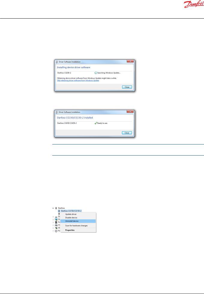
It is necessary to install CAN driver software before using the PLUS+1® Service Tool.
1.Plug in the PLUS+1® CG150-2 USB cable to the PC USB port. The Hardware Wizard searches for and installs CAN software. This may take several minutes.
2.Click Close to close the Driver Software Installation dialog. The following message appears when installation is complete.
USB drivers can be found in the directory: <Program Files>\Danfoss\PLUS1\<Service
Tool Version>\Misc\.
CAN hardware installation troubleshooting
To resolve issues related to the Danfoss PLUS+1®CG150-2 CAN/USB gateway interface communicator, perform the following procedure:
1.Close the PLUS+1® Service Tool.
2.Enter the Device Manager in Windows® operating system by selecting: Control Panel > System >
Device Manager.
3.Select PLUS+1® CG150-2 or PLUS+1® Display under the Danfoss > Device Manager.
4.Right-click Danfoss CG150-2 or Display and select Uninstall.
8 | © Danfoss | February 2021 |
AQ152986484649en-001003 |

User Manual
PLUS+1® Service Tool
PLUS+1® hardware setup
5. Ensure that the Delete the driver software for this device option is unchecked, then click OK.
6.Unplug the PLUS+1® CG150-2 then plug it back into PC USB port.
The Found New Hardware balloon should appear in the Windows® taskbar. Complete the driver installation wizard and start the PLUS+1® Service Tool to re-establish connection with the PLUS+1® CG150-2.
Using the PLUS+1® CG150-2 USB/CAN Gateway Interface Communicator
Select Communication > Gateway > CG150-2 from the PLUS+1® Service Tool window menu.
Using the PLUS+1® DP Series Display USB/CAN gateway
PLUS+1® DP Series Displays with USB connectivity can be used as a CAN gateway.
Make sure that the display is connected using a supported USB cable (see product documentation).
© Danfoss | February 2021 |
AQ152986484649en-001003 | 9 |
User Manual
PLUS+1® Service Tool
PLUS+1® hardware setup
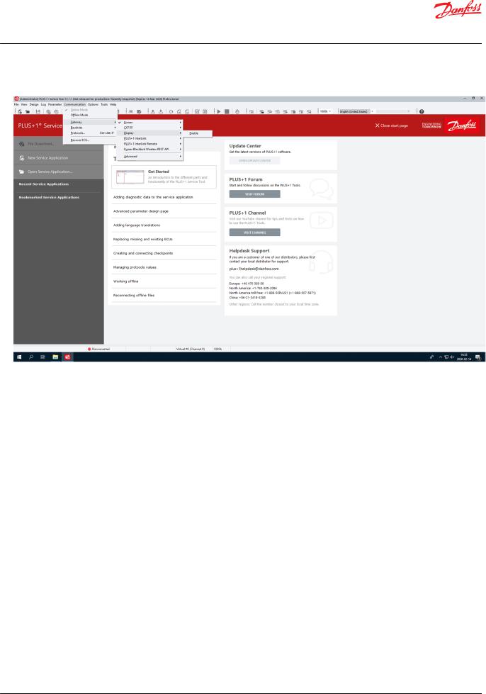
Select Communication > Gateway > Enable from the PLUS+1® Service Tool window menu.
Diagnose will be a choice under Gateway to select to examine any detected errors and warnings.
Using the PLUS+1® InterLink gateway
PLUS+1® products with PLUS+1® InterLink capabilities can be used as a gateway.
1.Make sure that the device is accessible through Wi-Fi/Ethernet/Bluetooth/USB (see product documentation).
10 | © Danfoss | February 2021 |
AQ152986484649en-001003 |
User Manual
PLUS+1® Service Tool
PLUS+1® hardware setup
2.Select Communication > Gateway > PLUS+1 InterLink from the PLUS+1® Service Tool window menu.
The PLUS+1® Service Tool will search for available PLUS+1® InterLink devices, and these devices will be available as channels.
3.After selecting the desired channel, a Gateway Password dialog will show up if the gateway is password protected. Enter the correct password and press the Connect button to connect.
4.Check the Remember password check box to save the password.
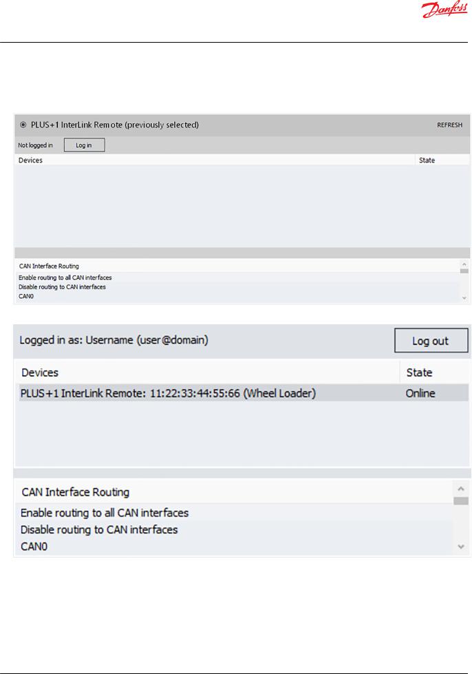
Using the PLUS+1® InterLink Remote gateway
PLUS+1® products with PLUS+1® InterLink Remote capabilities can be used as a gateway.
1.Select Communication > Gateway > PLUS+1®InterLink Remote from the PLUS+1® Service Tool window menu.
© Danfoss | February 2021 |
AQ152986484649en-001003 | 11 |
User Manual
PLUS+1® Service Tool
PLUS+1® hardware setup
2.Click Log in to log in or sign up for a Danfoss Profile. Once authenticated the device list will display the list of your PLUS+1® InterLink Remote devices and the state of each device. Click Refresh to the update the state of the available devices.
3. Click OK to connect to the selected device.
By default, routing to all CAN interfaces is enabled. This means that any PLUS+1® device connected to the CAN interfaces of the remote gateway will be accessible in PLUS+1® Service Tool. This functionality can be configured in the CAN Interface Routing list before connecting to the device.
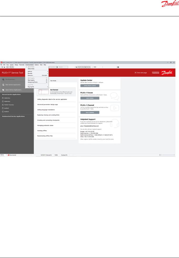
Using the third party Gateway devices via the RP1210 standard
The PLUS+1® Service Tool supports the generic communication standards RP1210B & RP1210A for any compliant third party gateway. These recommended practice standards were written by the Technology and Maintenance Council (TMC).
12 | © Danfoss | February 2021 |
AQ152986484649en-001003 |

User Manual
PLUS+1® Service Tool
PLUS+1® hardware setup
•RP1210B gateways may not support all baudrates that the built-in gateways support.
‒RP1210B gateways can be used if they support the generic CAN protocol.
•RP1210A gateways only supports baudrates equal to 250k. RP1210A gateways can be used if they:
‒Support the generic CAN protocol
‒Support blocking calls
‒Use the same endianness (byte order) for CAN messages as RP1210B
•Activate RP1210 gateways by selecting the appropriate DeviceID in the submenu under the gateway submenu. All possible device IDs will be listed for selection. Devices do not need to be connected to the computer to be listed.
Connection
When an RP1210B or RP1210A gateway has been properly installed, it will be automatically added to the list of installed gateways under Communication > Gateway after the PLUS+1® Service Tool is restarted.
The name of the new gateway consists of the name of the standard implemented (RP1210B or RP1210A) plus the name of the gateway vendor as written in the vendor supplied .ini file. The order of gateways in the list is determined by the global RP121032.ini file.
Diagnosing gateway warnings and errors using the RP1210 standard
Configure an RP1210 gateway using its .ini file. It is important that the .ini file follows the standard.
If the PLUS+1® Service Tool has problems reading the .ini file, an error or a warning message will occur. If an error is found, it will not be possible to use the gateway from the PLUS+1® Service Tool. If warnings are found it will still be possible to use the gateway, but a communication slowdown will occur. This slowdown can be overridden by the user. See Using Reset Gateway in advanced settings on page 13 to fix a gateway error manually.
Diagnose will be a choice under Gateway to select to examine any detected errors and warnings.
Advanced users may wish to use the View RP1210 parse log to troubleshoot RP1210 gateways that may not be working well with the PLUS+1® Service Tool.
Select Communication > Gateway > Advanced > RP1210 Log from the PLUS+1® Service Tool window menu.
The contents shown in the RP1210 Parse Results window is generated from the code and never stored in a specific file.
A gateway that does not implement RP1210B, but only RP1210A will generate a warning message.
Using Reset Gateway in advanced settings
Reset Gateway can be used to:
© Danfoss | February 2021 |
AQ152986484649en-001003 | 13 |

User Manual
PLUS+1® Service Tool
PLUS+1® hardware setup
•Search for gateway changes
•Manually fix a gateway error that is not automatically detected
14 | © Danfoss | February 2021 |
AQ152986484649en-001003 |
User Manual
PLUS+1® Service Tool
Managing protocols
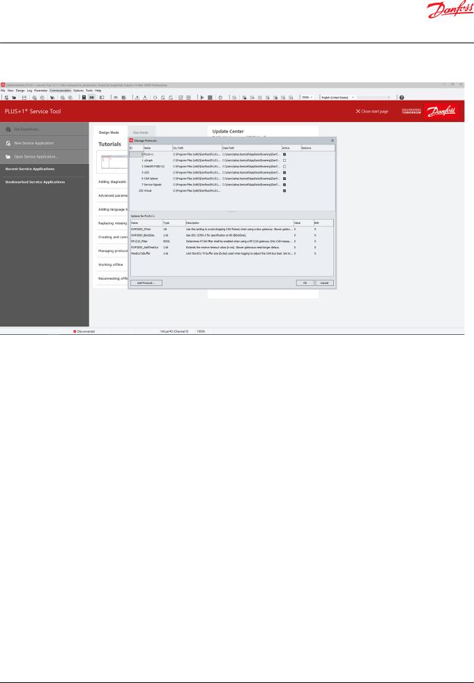
Managing Protocols values
Protocols must be installed and selected before they can be used. This can be done in the Manage Protocols window. More than one protocol can be used at a time.
The PLUS+1® Service Tool also supports the use of communication protocols other than the standard PLUS+1® protocol, but not all PLUS+1® features may be functional if a different protocol is used.
To manage communication protocols, select: Communication > Protocols....
This opens the Manage Protocols window, see below:
© Danfoss | February 2021 |
AQ152986484649en-001003 | 15 |
User Manual
PLUS+1® Service Tool
Managing protocols
Selecting Add Protocol opens the window, where all installed protocols can be seen and managed. The Manage Protocols window displays the following values:
Manage Protocols Values
ID |
All protocols have an assigned ID number from 0 to 255. PLUS+1® protocol is always 0 |
|
and Virtual is always 255. |
Name |
Protocol name. |
|
|
DLL Path |
Location folder of actual DLL file. |
|
|
Data Path |
Location of a created folder where protocol-related information can be stored. This |
|
location can be changed by the user. |
Active Selection Box |
Check box checked: protocol is active. |
|
|
Remove |
Link to remove protocol from system. |
|
|
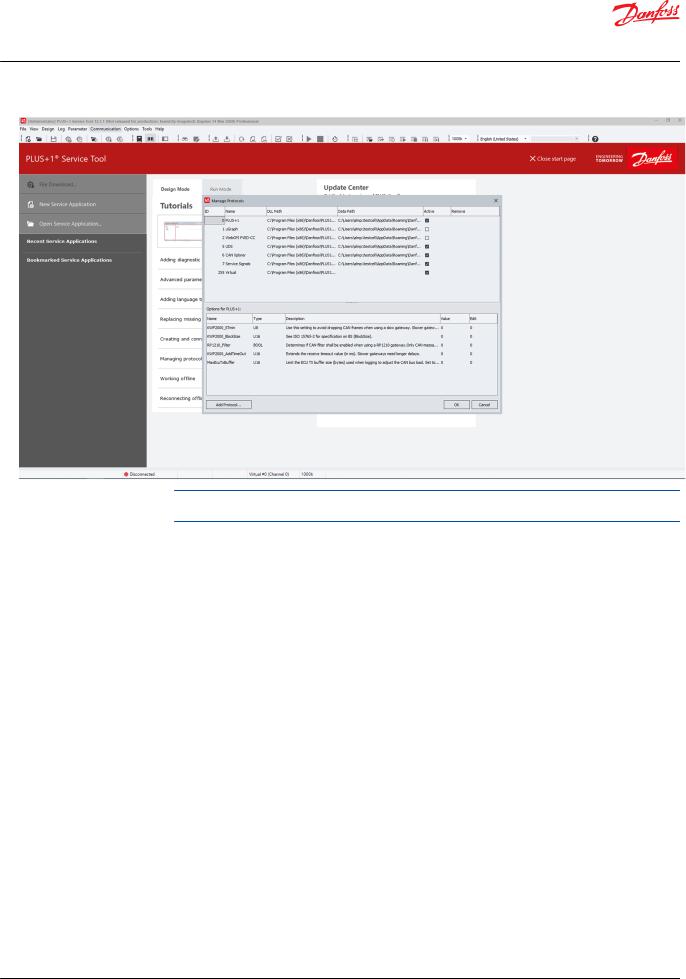
Add new protocols
1.Add new protocols by clicking the Add Protocol button in the lower left corner of the Manage Protocols window.
2.Select a protocol DLL in the Select Protocol DLL dialog and click Select to confirm the choice.
The added protocol will now appear in the protocols list of the Manage Protocols window with an assigned ID number.
3.Use the Manage Protocols window to check data path, activate, remove or modify options for the protocol. When finished, click OK.
The protocol is added and ready for use.
16 | © Danfoss | February 2021 |
AQ152986484649en-001003 |
User Manual
PLUS+1® Service Tool
Managing protocols
When using multiple protocols in a system, make sure that the protocols will not interfere with each other. High bus load may occur when using many protocols at the same time.
© Danfoss | February 2021 |
AQ152986484649en-001003 | 17 |
User Manual
PLUS+1® Service Tool
Managing protocols
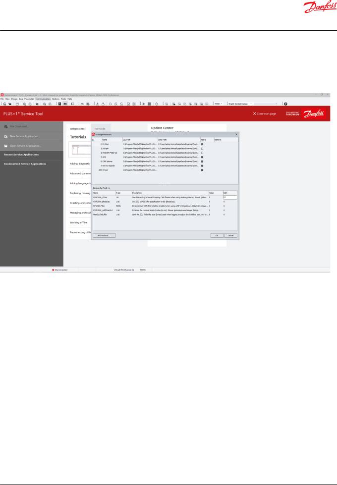
Protocol options
Protocol option values can be changed. In the Manage Protocols window, select a protocol in the list to view the protocol options displayed in the bottom part of the dialog. The options and information for each protocol will vary.
Options for protocol window
Name |
The name of the option. |
|
|
Type |
Setting type. |
|
|
Description |
A short description of the setting. |
|
|
Value |
The current value of the setting. |
|
|
Edit |
The editable properties of the setting. If field is empty, the setting is not editable (see editing |
|
properties for more information). |
|
|
Click the value in the Edit field to edit the option value. Click OK to save and use the updated option values.
18 | © Danfoss | February 2021 |
AQ152986484649en-001003 |
User Manual
PLUS+1® Service Tool
PLUS+1 Service Tool window
PLUS+1® Service Tool Window Description
Ite |
Name |
Description |
m |
|
|
|
|
|
1. |
Menu bar |
Use to access PLUS+1® Service Tool commands and information. |
2. |
Toolbar |
Use to access common PLUS+1® Service Tool commands and information. |
3. |
System Navigator |
Use to show a tree view of all hardware and software applications within the PLUS+1® |
|
|
Service Tool. |
|
|
|
4. |
Work area |
The area where all PLUS+1® Service Tool functions are performed. |
5. |
Service function |
Displays information of current PLUS+1® Service Tool function. |
|
status |
|
|
|
|
6. |
Controller |
• Green — Controller connected |
|
connection status |
• Blue — Logging or Downloading |
|
|
• Yellow — Searching for connection |
|
|
• Red — Controller disconnected or gateway error |
|
|
|
7. |
Log period status |
Displays the requested and actual log period settings in the application. |
|
|
|
8. |
CAN device |
Displays connected CAN/USB gateway interface communicator information. |
|
information |
|
|
|
|
9. |
CAN baudrate |
Displays the baudrate setting for the CAN/USB gateway interface communicator. |
|
|
|
© Danfoss | February 2021 |
AQ152986484649en-001003 | 19 |

User Manual
PLUS+1® Service Tool
PLUS+1 Service Tool window
Start page
The start page is available by default when no Service Application is open in PLUS+1® Service Tool. It can be disabled in Options under General (or new page number if changed).
PLUS+1 Service Tool start page
Item |
Description |
|
|
File Download… |
Displays the Open Download File dialog. Once a file is |
|
selected, the Download File dialog is displayed. |
|
|
New Service Application |
Creates a new empty Service Application. |
|
|
Open Service Application... |
Displays the Open Service Application dialog. Use this |
|
dialog to locate and open Service Application files. |
|
|
Recent Service Applications |
A list of recently opened Service Applications. Select a |
|
Service Application to open from this list. |
|
|
Bookmarked Service Applications |
A list of bookmarked Service Applications. Select a |
|
Service Application to open from this list. |
|
|
Tutorials |
A list of tutorial links into the HTML version of the user |
|
and design manuals. |
|
|
Update Center |
Shortcut to start the PLUS+1® Update Center. |
PLUS+1® Forum |
Shortcut to the PLUS+1® Forum online. |
PLUS+1® Channel |
Shortcut to the PLUS+1R YouTube channel. |
Helpdesk Support |
Contact information to PLUS+1® Helpdesk. |
20 | © Danfoss | February 2021 |
AQ152986484649en-001003 |
User Manual
PLUS+1® Service Tool
PLUS+1 Service Tool window
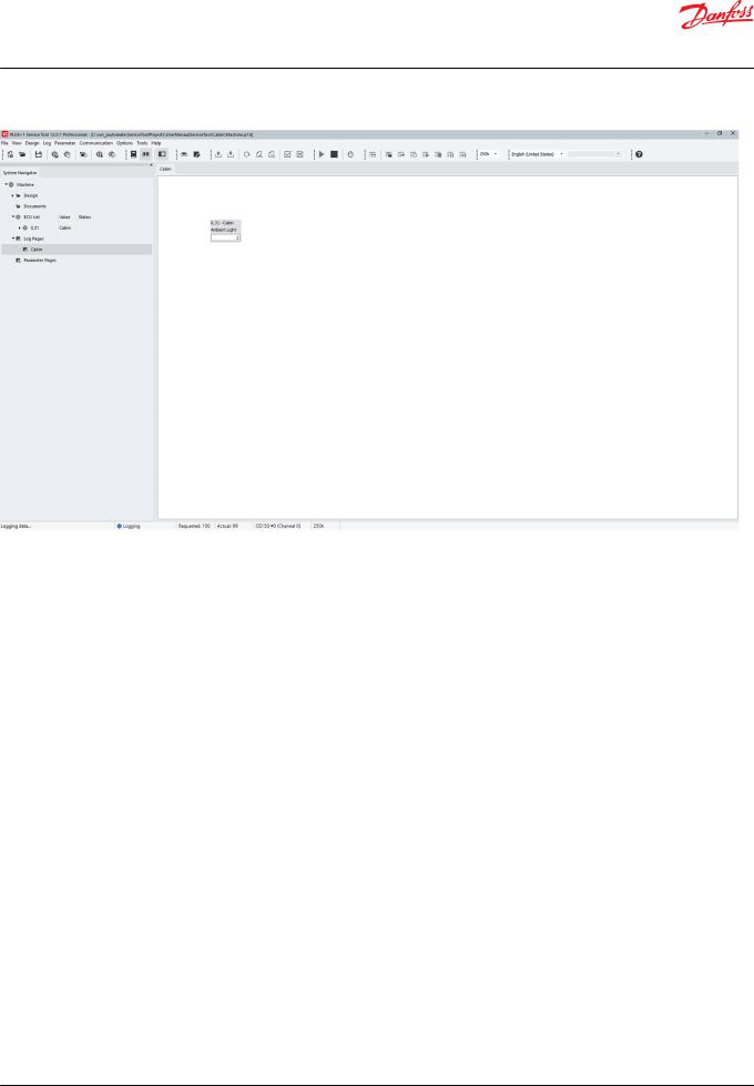
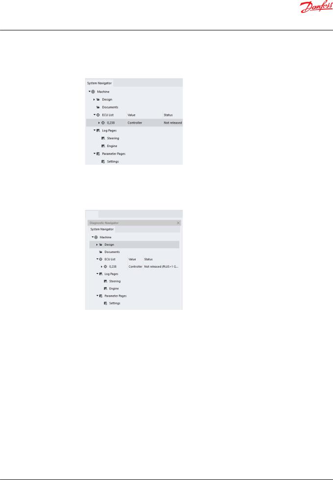
System Navigator features
The System Navigator section of the PLUS+1® Service Tool window contains and displays important information for the PLUS+1® Service Tool.
It is possible to copy the ECU list information to the clipboard, by right-clicking the ECU List node and selecting the menu item Copy ECU List to clipboard.
The System Navigator area is the starting point for all PLUS+1® Service Tool functions.
Use the System Navigator to:
•Set and display system information
•Store and access documents (right click on Documents icon to add, remove or hide documents in Normal view)
•Set and display ECU information
•Display Net, node and hardware information
•Create, open and arrange Log and Parameter pages
•Store and display PLUS+1® Service Tool activity history
Information in the System Navigator is arranged in a hierarchical style. Sections can be expanded or minimized as needed.
Locking and unlocking Diagnostic Navigator pane
Unlock the Diagnostic Navigator pane
© Danfoss | February 2021 |
AQ152986484649en-001003 | 21 |
User Manual
PLUS+1® Service Tool
PLUS+1 Service Tool window
1.Drag the pane by the undocking bar to separate it from the main window.
Drag to unlock (docked)
Lock the Diagnostic Navigator pane
2.Double-click on the title bar at the top of the window. The Navigator pane snaps to its default position.
Double-click to dock (undocked)
Hide the Diagnostic Navigator pane
3.Toggle either the Diagnostic Navigator button in the status bar or Diagnostic Navigator in the View menu.
Display the Diagnostic Navigator pane
4.Move the mouse cursor to the left side of the PLUS+1® Service Tool window or click the System Navigator button on the toolbar again.
Restoring default layouts
Select View > Default Layout to restore the PLUS+1® Service Tool window settings to the default layout.
22 | © Danfoss | February 2021 |
AQ152986484649en-001003 |
User Manual
PLUS+1® Service Tool
PLUS+1® Service Tool languages
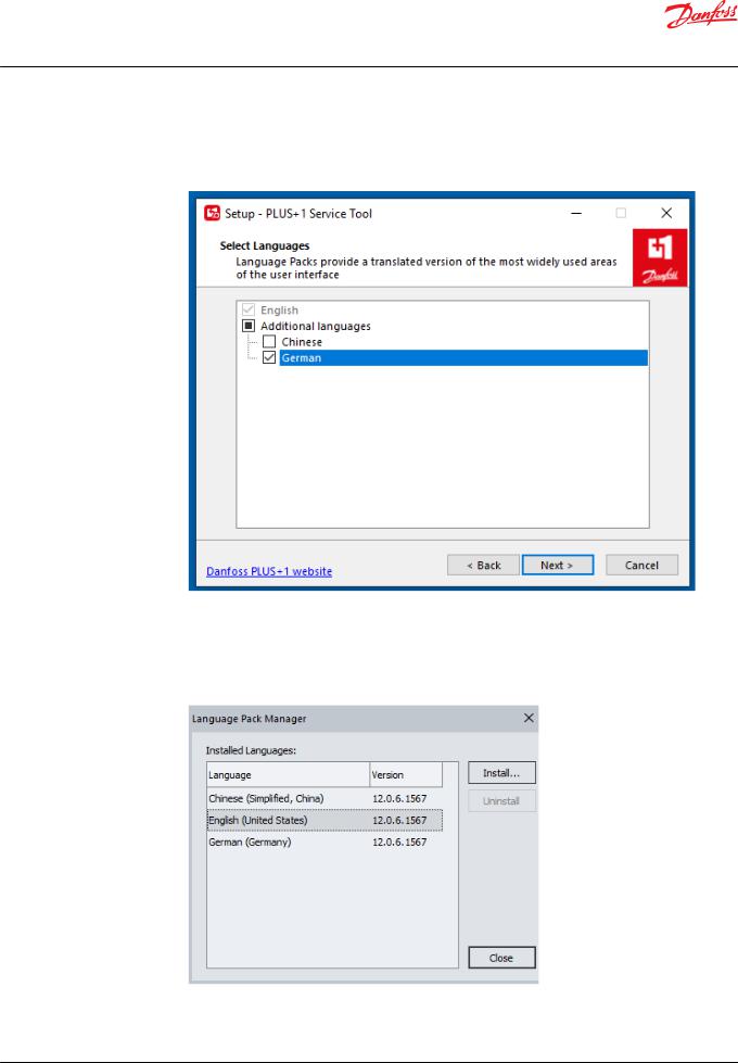
Installing tool languages during setup
When setting up the PLUS+1® Service Tool, install additional languages in the Select Languages page.
Managing languages in PLUS+1® Service Tool
1.In the PLUS+1® Service Tool, select Tools > Language > Language Manager.
2.Select language to install or uninstall.
You cannot uninstall the default language (English).
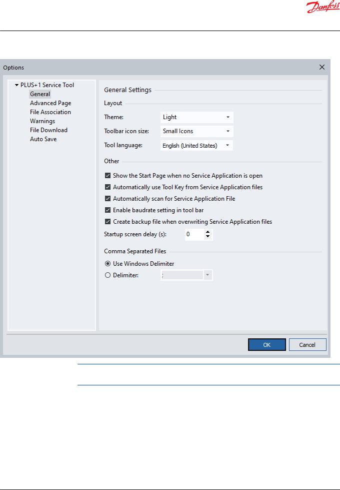
Selecting the PLUS+1® Service Tool language
To select the preferred PLUS+1® Service Tool language, select Tool language in the General Settings.
© Danfoss | February 2021 |
AQ152986484649en-001003 | 23 |
User Manual
PLUS+1® Service Tool
PLUS+1® Service Tool languages
To select the default language (English), select Options > Language > Default Tool Language. This can also be done by selecting Ctrl+Alt+F.
Selecting the Service Application language
24 | © Danfoss | February 2021 |
AQ152986484649en-001003 |

User Manual
PLUS+1® Service Tool
PLUS+1® Service Tool languages
When a multilingual Service Application is active and the tool is in Normal View, select Tools >
Language > Select Service Application Language.
Alternatively, you can select the preferred language in the drop-down list of the toolbar.
© Danfoss | February 2021 |
AQ152986484649en-001003 | 25 |
Loading...