


Data sheet
Self-acting controllers integrated to heat exchanger (PN16)
IHPT, Termix TPV – Flow-compensated temp. controller with ∆p controller built in (NO)
Description
IHPT
Self-acting controllers are designed to be integrated directly to heat exchanger. They are developed to control instantaneous heating of domestic hot water by means of heat exchanger.
The family of products offer full flexibility of different requirements regarding control performance and idle condition (no load conditions).
Innovative design enables simple, fast and reliable connection to heat exchanger and most important production of ultra compact and user friendly stations for heating of domestic hot water.
The capacity of controllers fully covers the needs of domestic hot water for flats, one family houses or dwellings and can be mounted to district heating network directly, to a block of heating systems or central located boiler system in a dwelling house.
The controller is connected to primary heating system as well as cold water system. To avoid risk of leaking from one media to the other the controller is equipped with double sealing. Between both sealings there is a bore to the outside of the valve. In case of leakage from one sealing the media can escape through the bore.
There are two different controller housings:
-original (IHPT)
-Gemina housing (Termix TPV)
Termix TPV controller has the same function as IHPT controller, but different (Gemina) housing.
Controllers have:
-WRAS approval,
-ETA VA approval.
Main data:
•DN 15
•kVS 2,4; 3,0 m3/h
•PN 16
•Setting range: 45 ... 65 °C
•Temperature:
Circulation water 2 ... 120 °C
•Connections:
-Union nut
-External thread
© Danfoss | 2017.02 |
VD.LY.A2.02 | 1 |
Data sheet |
Controller IHPT and Termix TPV |
Ordering
Example 1:
Flow-compensated temperature controller with ∆p controller built in (NO); 90O version; not damped;
DN 15; kVS 2,4; PN 16; setting range 45 ... 65 °C; union nut connection
- 1× IHPT DN 15 controller Code No: 003L3875
Option:
- 1× Housing of sensor stuffing box
Code No: 013U8102
IHx Controllers, 90° version - Damped 1)
Picture |
Type |
DN |
kVS |
Setting range 4) |
Connection 2) |
Code No. |
|
(m3/h) |
(°C) |
||||||
|
|
|
|
|
|||
|
IHPT 3) |
15 |
2,4 |
45 … 65 |
Union nut |
003L3875 |
|
|
3,0 |
003L3877 |
|||||
|
|
|
|
|
|||
|
Termix TPV |
15 |
3,0 |
45 … 65 |
Union nut |
003L3914 |
1)For details see “Selection guideline” section
2)to heat exchanger
3)Controller is delivered with thermostatic actuator with standard sensor and M14 sensor stuffing box (housing of sensor stuffing box is not delivered, it is available as an accessory)
4)see Setting range section
IHx Controllers, miscellaneous versions - Damped 1)
Picture |
Type 3) |
DN |
kVS |
Setting range 4) |
|
Version |
Connection 2) |
Code No. |
(m3/h) |
(°C) |
|
||||||
|
|
|
|
|
|
|
||
|
Termix TPV (IHPT) |
15 |
3,0 |
45 … 65 |
180° |
Gemina |
Union nut |
003L3915 |
|
housing |
|||||||
|
|
|
|
|
|
|
|
1)For details see “Selection guideline” section
2)to heat exchanger
3)Controller is delivered with thermostatic actuator with standard sensor and M14 sensor stuffing box (housing of sensor stuffing box is not delivered, it is available as an accessory)
4)see Setting range section
Accessories
Type designations |
Code No. |
|
|
Housing of sensor stuffing box 1) |
013U8102 |
1)Code includes housing and gasket of sensor stuffing box; R ½ × M14 × 1 mm, rubber EPDM Ø 12,6 × 4 × 6 mm
Service kits
Type designations |
Setting range |
Code No. 1) |
|
(°C) |
for IHPT |
||
|
|||
Service thermostat |
40 … 60 |
003L3868 |
|
|
|
|
|
Thermostatic actuator with |
45 … 65 |
003L3833 |
|
standard sensor |
|||
|
|
1)For details see “Installation positions” section; sensor is delivered with M14 sensor stuffing box
2 | © Danfoss | 2017.02 |
VD.LY.A2.02 |
Data sheet |
Controller IHPT and Termix TPV |
Technical data
Nominal diameter |
DN |
|
15 |
|
kVS value of thermostatic controller (kvs, TC) |
m3/h |
2,4 |
|
3,0 |
kVS value of built in ∆p controller (kVS, DP ) |
|
5,0 |
||
|
|
|||
Controlled ∆p on thermostatic cont. (ΔpTC) |
bar |
|
0,16 |
|
Min. flow rate on primary side (Q1,min) |
|
70 |
|
100 |
Max. flow rate on primary side (Q1,max) |
l/h |
1000 |
|
1200 |
Min. flow rate on secundary side (Q2,min) |
|
120 |
||
|
|
|||
Max. rec. flow rate on secondary side (Q2,max) |
|
|
1400 4) |
|
Nominal pressure |
PN |
|
16 3) |
|
Max. diff. pressure on primary side |
bar |
|
6 |
|
|
|
|
|
|
Max. rec. diff. pressure on secondary side |
|
1,0 |
||
|
|
|||
|
|
|
|
|
Medium |
|
Circulation water / glycolic water up to 30 % 1) |
||
|
Domestic hot water (chlorine (cl) content max. 200 ppm) 2) |
|||
|
|
|||
Medium pH |
|
|
Min. 7, max. 10 3) |
|
Medium temperature |
|
|
2 ... 120 |
|
|
|
|
|
|
Setting range |
ºC |
|
45 … 65 |
|
|
|
|
|
|
Idle temperature |
|
Tset – 8 °C |
||
|
|
|||
|
|
|
|
|
Max. adm. temperature at sensor |
|
|
120 |
|
|
|
|
|
|
Capillary tube length |
m |
|
0,6 |
|
Materials |
|
|
|
|
|
|
|
|
|
Housings |
|
|
CuZn21Si3P (CW724R) |
|
|
|
|
|
|
Cone and diaphragm support |
|
|
MPPE (Noryl) |
|
|
|
|
||
Main spindle |
|
Stainless steel, mat. No. 1.4404 |
||
|
|
|
|
|
Diaphragm, O-rings |
|
|
EPDM |
|
|
|
|
|
|
Temperature sensor |
|
|
Copper, mat. No. 2.0090 |
|
|
|
|
|
|
1)valid for primary side
2)valid for secondary side
3)on primary and secondary side
4)at diff. pressure on secondary side (Δp2 ) 1 bar
Classification according to VDI 6003
Type |
Wash basin 1) |
Showers 2) |
IHPT, Termix (TPV) |
III |
III |
1)Tapping rate changing in steps of 6-12-6 l/min.
2)Tapping rate changing in steps of 9-12-9 l/min.
The min. required differential pressure across primary side of the controller is calculated from the formula:
|
|
|
QPRIM,max |
|
2 |
|
|
Δp |
PRIM,min |
= |
|
+Δp |
TC |
||
|
|||||||
|
|
k VS,DP |
|
|
|||
|
|
|
|
|
|
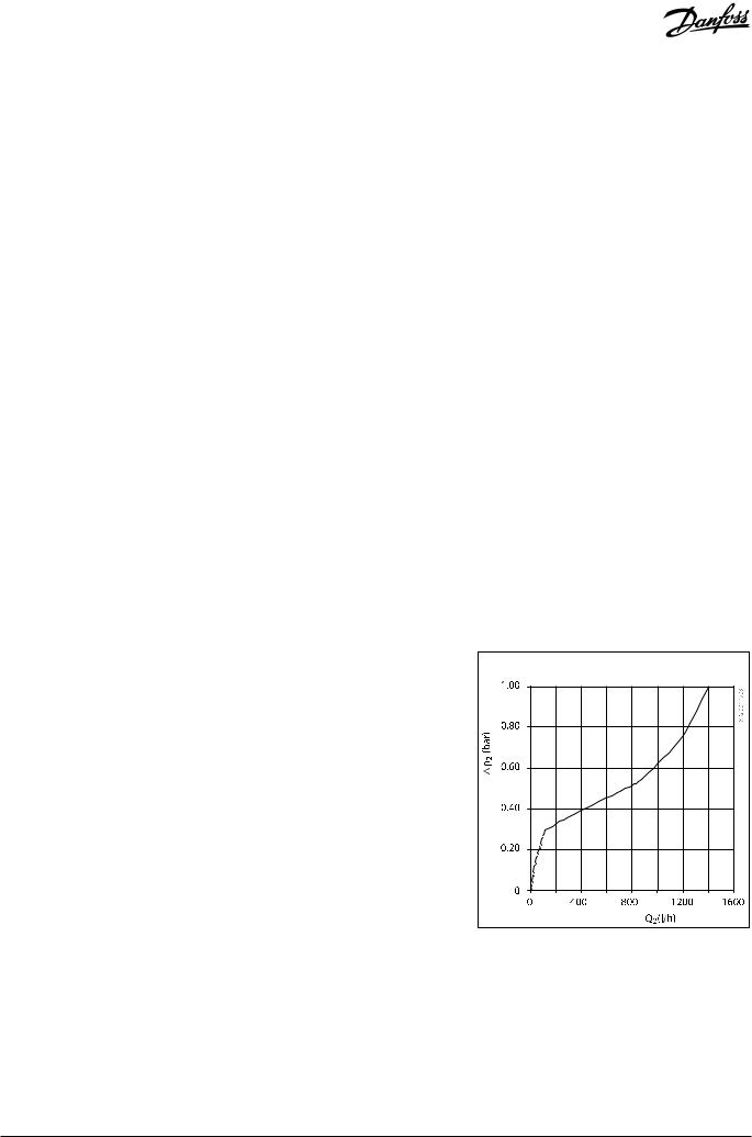
In graph pressure drop on secondary side in relation to the secondary flow can be seen.
* |
TC - thermostatic controller |
Quick suggestion:
If the max. flow rate on primary side is below 1 m3/h (1000 l/h) always choose kVS = 2,4 m3/h and if it is higher then choose kVS = 3,0 m3/h.
Measured for constant supply temperature of 75 °C and system differential pressure of 0,5 bar.
Secondary side |
VD.LY.A2.02 |
© Danfoss | 2017.02 | 3 |

Data sheet |
Controller IHPT and Termix TPV |
Setting range
Valid for thermostatic controllers IHPT and Termix TPV
Setting range 45 ... 65 |
Temperature setting depends on application parameters. Values given are approximate.
Selection guideline
Type |
Application |
Description |
|
|
|
|
Functions |
|
|
|
Flow-compensated temp. controller with |
|
|
|
differential pressure controller built in (N0) |
|
IHPT |
|
Typical system conditions |
IHPT, |
TC |
DP |
District heating systems with varying supply |
Termix TPV |
|
|
temperature plus high and varying differential |
|
QC |
|
pressure and where a high comfort idle |
|
|
temperature is requested. |
|
|
|
|
|
|
|
|
Idle control alternatives |
|
|
|
Idle controller is built in. |
Application principle |
|
4 | © Danfoss | 2017.02 |
VD.LY.A2.02 |
 Loading...