


Installation Guide
Gas Detection Unit (GDU) |
Info for UK customers only: |
|
Danfoss Ltd. |
||
|
||
GDA, GDC, GDHC, GDHF, GDH |
Oxford Road, UB9 |
|
4LH Denham, UK |
<![endif]>148R9631
ENGLISH
Technician use only! |
Please observe that a Danfoss GDU works as a safety device |
This unit must be installed by a suitably qualified technican who |
securing a reaction to a detected high gas concentration. If a |
will install this unit in accordance with these instructions and the |
leakage occur, the GDU will provide alarm functions, but it will |
standards set down in their particular industry/country. |
not solve or take care of the leakage root cause itself. |
<![endif]>148R9631
Suitably qualified operators of the unit should be aware of the regulations and standards set down by their industry/country for the operation of this unit.
These notes are only intended as a guide and the manufacturer bears no responsibility for the installation or operation of this unit.
Failure to install and operate the unit in accordance with these instructions and with industry guidelines may cause serious injury including death and the manufacturer will not be held responsible in this regard.
It is the installer’s responsibility to adequately ensure that the equipment is installed correctly and set up accordingly based on the environment and the application in which the products are being used.
Annual Test
To comply with the requirements of EN378 and the F GAS regulation sensors must be tested annually. Danfoss GDU's are provided with a test button that should be activated once a year for testing of the alarm reactions.
Additional the sensors must be tested for functionality by either Bump test or Calibration. Local regulations should always be followed
After exposure to a substantial gas leak, sensor should be checked and replaced if necessary.
Check local regulations on calibration or testing requirements.
Configurations and Wiring: All 3 types of Gas Detection Units (GDU)
Controller solution
Gas Detection Controller
Max. 96 sensors
Option: Modbus


Option: UPS
Wire break monitoring unit
| <![if ! IE]> <![endif]>Premium |
<![if ! IE]> <![endif]>Premium+ |
<![if ! IE]> <![endif]>Premium Flex |
<![if ! IE]> <![endif]>Premium Remote |
<![if ! IE]> <![endif]>Premium Duplex |
<![if ! IE]> <![endif]>Premium Uptime |
Display |
<![if ! IE]> <![endif]>Heavy Duty |
| <![if ! IE]> <![endif]>Basic |
<![if ! IE]> <![endif]>Basic + |
|
|
UPS |
|
Sensor |
|
Sensor |
|
Sensor |
|
sor |
|
Buzzer and light |
|
|
and light |
|
|
color-alarm |
|
|
|
-alarm |
5 meter |
|
|
|
|
|
remote sensor |
Basic GDU |
Premium GDU (Controller) |
Heavy Duty GDU |
2 configurations |
6 configurations |
1 configuration |
1
Service tools
Service Tool
Handheld
Danfoss Pen for Heavy Duty display communication
<![if ! IE]><![endif]>Danfoss 148H118_03-2018
| Climate solutions | 2021.06 |
AN272542819474en-000201 | 1 |
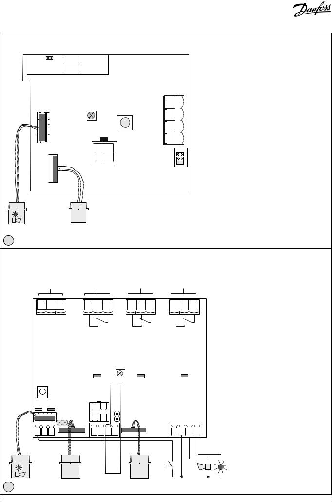
Danfoss Basic GDU |
|
|
|
|
|
|
|
|
|
|
|
|
|
|
|
|
|
|
|
||
|
JP5* |
|
|
5 |
GND |
|
|
|
|
|
|
|
|
|
|
|
|
|
|
||
Open: 4-20mA |
|
|
|
|
|
|
|
|
|
|
|
|
|
|
|||||||
|
|
|
|
|
|
|
|
|
|
|
|
|
|
|
|
|
|||||
Closed: 2-10V |
4 |
AO_01 |
|
|
|
|
|
|
|
|
|
|
|
|
|
|
|||||
|
|
|
|
|
X1 |
Analog Output |
|
|
|
|
|
|
|
|
|
|
|
||||
|
|
|
|
|
|
|
|
|
|
Ackn. -/Test |
|
|
|
<![if ! IE]> <![endif]>4 |
|
|
|
Bus_B |
|
||
|
|
|
|
|
|
|
|
|
|
|
|
|
|
|
|
|
|
|
|
||
|
|
|
|
|
|
|
|
|
|
button T1 |
|
|
|
<![if ! IE]> <![endif]>3 |
|
|
|
Bus_A |
|
||
|
|
|
|
|
|
|
|
|
|
|
|
|
|
<![if ! IE]> <![endif]>X4 |
|
|
|
|
|||
|
|
|
|
|
|
Status LED |
|
|
|
|
|
<![if ! IE]> <![endif]>2 |
|
|
|
0 V AC/DC |
|||||
|
|
|
|
|
Green/Yellow/Red |
|
|
|
|
|
|
|
|
|
|
|
|
||||
|
|
|
|
|
|
|
|
|
|
|
|
|
|
|
<![if ! IE]> <![endif]>1 |
|
|
|
24 V AC/DC |
||
|
<![if ! IE]> <![endif]>X8 |
|
|
|
|
|
|
|
|
|
|
|
|
|
Jumper |
|
|
|
|||
|
|
|
|
|
|
|
|
|
|
|
|
|
|
|
|
|
|
|
|||
|
|
|
|
|
|
|
|
|
|
|
|
|
|
|
|
|
|
J1 |
|
|
|
|
|
|
|
|
|
|
|
|
|
|
|
|
|
|
|
|
|
J2 |
|
|
|
|
|
|
|
|
|
|
|
|
|
|
|
|
|
|
|
|
|
J3 |
|
|
|
|
|
|
|
|
|
|
|
X9 |
|
|
|
|
|
|
|
|
|
|
|
|
|
|
|
|
|
<![if ! IE]> <![endif]>X2 |
|
|
Service Tool |
|
|
|
|
|
|
|
|
|
|
|
|||
|
|
|
|
|
|
|
|
|
|
|
|
|
|
|
|
|
|
|
|
|
|
3-light alarm |
|
|
|
|
|
|
|
|
|
|
|
|
|
|
|
|
<![if ! IE]> <![endif]>11-2018 |
|
|||
|
|
|
|
|
|
|
|
|
|
|
|
|
|
|
|
<![if ! IE]> <![endif]>Danfoss 148H119 |
|
||||
Buzzer & |
|
|
Sensor |
|
|
|
|
|
|
|
|
|
|
|
|
|
|
|
|||
2 |
|
|
|
|
|
|
|
|
|
|
|
|
|
|
|
|
|
|
|
|
|
Danfoss Premium GDU |
|
|
Relays 1 and 2 de-energized (default) |
Relay 3 energized (default) |
|
||||||||||||||||
|
|
|
|
|
|
|
|||||||||||||||
|
|
|
|
|
|
|
in operating mode at No alarm. |
|
in operating mode at No alarm. |
||||||||||||
|
|
|
|
|
|
|
|
|
Configurable |
|
|
|
|
Configurable |
|
|
|||||
|
Power 24 V DC |
|
|
Relay 1 |
|
|
Relay 2 |
|
|
|
|
Relay 3 |
|
|
|
||||||
|
|
Alarm 1 |
|
|
Alarm 2 |
|
|
|
|
Error |
|
|
|
||||||||
|
|
3 |
2 |
1 |
|
3 |
|
2 |
1 |
|
3 |
2 |
1 |
|
|
3 |
2 |
1 |
|
||
|
|
|
|
|
X1 |
|
|
|
|
X2 |
|
|
|
X3 |
|
|
|
|
|
X4 |
|
|
<![if ! IE]> <![endif]>V DC |
<![if ! IE]> <![endif]>GND |
<![if ! IE]> <![endif]>NC |
|
|
|
|
|
|
|
|
|
|
|
|
|
|
|
|
|
|
|
<![if ! IE]> <![endif]>24 |
|
|
|
|
|
|
|
Relays shown de-energized |
|
|
|
|
|
|
||||||
|
|
|
|
|
|
|
|
|
|
|
|
|
|
|
|
||||||
|
|
|
|
|
|
|
|
|
Status LED |
|
|
|
|
|
|
|
|
|
|
|
|
|
|
|
|
|
|
|
|
Green/Yellow/Red |
|
|
|
|
|
|
|
|
|
|
|||
|
Ackn./Test |
|
|
Relay status |
Relay status |
|
|
Relay status |
|
||||||||||||
|
button |
|
|
|
|
|
|||||||||||||||
|
|
|
LED Green |
open:4-20mAJP2*closed:2-10V |
LED Green |
|
|
LED Green |
|
||||||||||||
|
|
|
|
|
|
|
|
|
|||||||||||||
|
|
|
|
|
|
Service Tool |
|
|
|
|
|
|
Digital |
<![if ! IE]> <![endif]>light |
|
||||||
|
|
|
|
|
|
|
|
|
|
|
|
Output |
|
||||||||
|
|
|
|
|
|
|
|
|
|
|
|
|
|
|
|||||||
|
Power Bus Comm. |
|
|
|
|
|
|
|
|
|
|
|
|
|
|||||||
|
|
|
|
|
|
|
|
|
|
|
|
|
|
|
|
|
|||||
|
|
|
|
|
Local |
|
|
|
|
|
Bus_2 |
|
<![if ! IE]> <![endif]>NC |
<![if ! IE]> <![endif]>GND |
<![if ! IE]> <![endif]>Horn |
|
<![if ! IE]> <![endif]>Flash |
<![if ! IE]> <![endif]>2018-01 |
|||
|
|
|
|
|
Bus_1 |
|
|
|
|
|
Local |
|
|
|
|
|
|
|
|
||
| <![if ! IE]> <![endif]>X11 |
|
|
|
|
|
<![if ! IE]> <![endif]>X12 |
|
|
|
|
|
|
|
|
<![if ! IE]> <![endif]>X13 |
|
|
|
|
|
<![if ! IE]> <![endif]>_ |
1 |
2 |
3 |
|
|
1 |
2 |
3 |
4 |
|
|
|
|
4 |
5 |
6 |
|
7 |
<![if ! IE]> <![endif]>Danfoss 148H120 |
|||
|
|
|
|
|
|
|
|
|
|
|
|||||||||||
|
<![if ! IE]> <![endif]>DI 1 |
<![if ! IE]> <![endif]>DI 2 |
<![if ! IE]> <![endif]>GND |
|
|
|
<![if ! IE]> <![endif]>Bus A |
<![if ! IE]> <![endif]>Bus B |
<![if ! IE]> <![endif]>AO 01 |
<![if ! IE]> <![endif]>GND |
|
|
|
Ackn. |
|
|
|
|
|
|
|
|
Digital |
|
|
|
|
|
|
|
|
|
|
Button |
|
|
|
|
|
|
|||
|
|
Input |
|
|
|
Field |
Analog |
|
|
|
|
|
|
|
|
|
|
|
|||
|
Buzzer & |
|
Sensor |
|
Bus |
Output |
Sensor |
|
|
|
|
|
|
|
|
|
|||||
|
|
|
|
|
|
|
|
|
|
|
|
|
|
|
|
||||||
|
3-light alarm |
|
|
|
|
|
|
|
|
|
|
|
|
|
|
||||||
|
|
|
|
|
|
|
|
|
|
|
|
|
|
|
|
|
|
|
|||
3
Status LED:
GREEN is power on.
YELLOW is an indicator of Error.
-when the sensor head is disconnected or not the expected type
-AO is activated but nothing connected
-flashing when sensor is in special mode (e.g. when changing parameters)
RED on alarm, similar to the Buzzer & light alarm.
Ackn. -/Test button:
TEST - The button must be pressed for 20 sec.
-Alarm1 and Alarm2 is simulated, stop on release
ACKN. - Pressed while Alarm2, the audible warning switches off and goes back on after 5 min. when the alarm situation is still active.
*JP5 open →AO 4 – 20 mA (Default) JP5 closed →AO 2 – 10 Volt
NOTE:
A resistor comes installed on the analog output connections – if analog output is used, remove the resistor.
Status LED:
GREEN is power on.
YELLOW is an indicator of Error.
-when the sensor head is disconnected or not the expected type
-AO is activated but nothing connected
RED on alarm, similar to the Buzzer & light alarm.
Ackn. -/Test button:
TEST - The button must be pressed for 20 sec.
-Alarm1 and Alarm2 is simulated, stop on release
ACKN. - Pressed while Alarm2, the audible warning switches off and goes back on after 5 min. when the alarm situation is still active.
*JP2 open →AO 4 – 20 mA (Default) JP2 closed →AO 2 – 10 Volt
NOTE:
A resistor comes installed on the analog output connections – if analog output is used, remove the resistor.
© Danfoss | Climate solutions | 2021.06 |
AN272542819474en-000201 | 2 |

Danfoss Premium Uptime GDU
Power supply |
Relay 1 |
Relay 2 |
Relay 3 |
24 V DC |
AR 01 |
AR 02 |
AR 03 |
12 V
0.8 Ah
12 V
0.8 Ah
ACCU
|
|
|
|
|
|
|
|
|
90 - 240 V AC |
|
3 2 1 |
X1 |
3 2 1 |
X2 |
3 2 1 |
X3 |
3 2 1 |
V+ V- PE N L |
|
||
|
|
|
|
|
|
X4 |
|
|||
| <![if ! IE]> <![endif]>24 V DC |
<![if ! IE]> <![endif]>GND |
<![if ! IE]> <![endif]>ACCU |
|
|
|
|
|
|
<![if ! IE]> <![endif]>Power supply 90 - 240 V AC 24 V DC, 15 VA |
<![if ! IE]> <![endif]>-2018 |
|
|
|
|
|
|
|
|
|
|
<![if ! IE]> <![endif]>Danfoss 148H147 02 |
4
Danfoss Heavy Duty GDU (ATEX, IECEx approved)
Sensor PX2
1+24 V DC
2+24 V DC
3GND
4BUS_A
5BUS_B
64 - 20 mA output
7 |
|
Fault relais energized in |
|
|
operating mode at No alarm |
|
|
|
8 |
|
- Default |
|
|
|
9 |
|
Alarm relais de-energized in |
|
|
|
|
|
operating mode at No alarm |
|
|
|
10 |
|
- Default (Configurable) |
|
|
|
11 |
|
|
|
|
|
|
|
|
Danfoss |
|
|
148H122_11-2018 |
|
|
<![endif]>Danfoss 148H121_01-2018
NPT ¾”(ANSI B1.20.1)
Internal Thread
Se |
rv ice ool |
|
s |
|
|
T |
Statu LE |
D |
|||
|
|
|
|
.Button |
|
|
|
|
Ac |
kn |
Sensorhead |
|
|
|
|
||
NPT ¾”(ANSI B1.20.1)
Internal Thread
Sensor
5
Location of Sensors
Gas type |
Relative density (Air = 1) |
R717 Ammonia |
<1 |
R744 CO2 |
>1 |
R134a |
>1 |
R123 |
>1 |
R404A |
>1 |
R507 |
>1 |
R290 Propane |
>1 |
|
|
On board LED is similar to the display LED:
Green is power on
Yellow is an indicator of Error
-when the sensor head is disconnected or not the expected type
-AO is activated but nothing connected
RED on alarm
On board Ackn. -/Test button:
Test: The button must be pressed for 20 sec.
- Alarm is simulated, stop on release
Ackn.: Pressed while Alarm2, the audible warning switches off and goes back on after 5 min. when the alarm situation is still active (also possible over ESC button (use the magnetic Pen).
Recommended sensor location
Ceiling
Floor
Floor
Floor
Floor
Floor
Floor
6
© Danfoss | Climate solutions | 2021.06 |
AN272542819474en-000201 | 3 |
 Loading...