


Danfoss EVUL 1, EVUL 2, EVUL 3, EVUL 4, EVUL 5 Data sheet
...Data sheet
Solenoid valves
Type EVUL
EVUL solenoid valves are designed to fit into compact refrigeration systems. Available
in servo operated versions they can be applied in liquid, suction, and hot gas lines.
EVUL solenoid valves can be used in many different refrigeration systems and
are specially designed for:
yy Commercial refrigeration systems yy Refrigeration appliances
yy Liquid coolers
yy Ice cube machines
yy Mobile refrigeration systems yy Heat pump systems
yy Air conditioning units
Features |
yy Compact and light weight. |
yy Universal application for – liquid, suction, |
|
yy Fully hermetic construction in stainless steel. |
and hot gas applications. |
|
yy Laser welded bimetal connections. |
yy Minimum power consumption. |
|
yy High vibration resistance |
yy Simple and fast mounting of coil. |
|
yy Excellent leak integrity |
yy Encapsulated coils provide long |
|
yy Bimetal connections for fast soldering. |
life time even under extreme conditions. |
|
yy No need of wet cloth / heat sink by soldering. |
yy High MOPD capacity – up to 36 bar (522 psi) |
|
yy Servo operated mini piston, sturdy and |
yy Build in filter in the inlet. |
|
compact solenoid valve. |
|
Approvals |
• UL Recognized Component (Canadian and US) • |
Pressure Equipment Directive (PED) |
|
|
2014/68/EU |
|
• Low Voltage Directive (LVD) 2014/35/EU |
|
|
• |
RoHS II |
© Danfoss | DCS (az) | 2017.12 |
DKRCC.PD.BD0.C8.02 | 1 |
Data sheet | Solenoid valves, Type EVUL
Technical data
Rated liquid and suction vapor capacity are based on:
-evaporating temperature te = -10 °C,
-liquid temperature ahead of the valve tl = 25 °C,
-pressure drop in valve ∆p = 0.15 bar.
Rated hot gas capacity is based on:
-condensing temperature tc = 40 °C,
-hot gas temperature th = 65 °C
-subcooling of refrigerant Δtsub = 4 K
-Pressure drop across valve Δp = 0.8 bar
Refrigerants
R744, R22/R407C, R404A/R507, R410A, R134a, R407A, R23, R290, R407F, R448A, R449A, R450A, and R452A.
For complete list of approved refrigerants, visit www.products.danfoss.com and search for individual code numbers, where refrigerants are listed as part of technical data.
Special note for R290:
The EVUL is validated in accordance to ATEX, ISO 5149, IEC 60335, and UL. Ignition risk is evaluated in accordance to ISO 5149 and IEC 60335.
See safety note at the bottom of this page.
Max. working pressure
90 bar / 1305 psig
Ambient temperature
-40 °C / -40 °F – 50 °C / 122 °F
MOPD operating range
EVUL 1 – 8: 0.02 - 36 bar / 0.29 - 522 psi MOPD is measured with highest media and ambient temperature and 15% below nominal voltage.
MOPD (Max. Opening Pressure Differential) for media in gas form is approximately 0.97 bar greater.
Kv value is the water flow in m3 / hour at a pressure drop across valve ∆p = 1 bar,
ρ = 1000 Kg / m3.
Cv value is the water flow in [gal / min] at a pressure drop across valve Δp = 1 psi,
ρ = 10 lbs / gal
Humidity
Media temperature |
|
|
0 − 100% R.H. (0-97% R.H. non-condensation |
|||||
-40 °C / -40 °F – 105 °C / 221 °F |
|
condition if IP level is below IPX5). |
|
|||||
Liquid – Rated capacity [Kw] |
|
|
|
|
|
SI units |
||
Type |
R22/R407C |
|
R134a |
R404A/R507 |
R407A |
R410A |
R290 |
KV value |
|
[m3 / hour] |
|||||||
|
|
|
|
|
|
|
|
|
EVUL 1 |
2.01 |
|
1.65 |
1.38 |
1.85 |
2.02 |
2.24 |
0.10 |
EVUL 2 |
4.02 |
|
3.31 |
2.76 |
3.70 |
4.04 |
4.48 |
0.20 |
EVUL 3 |
6.03 |
|
4.96 |
4.14 |
5.55 |
6.06 |
6.72 |
0.30 |
EVUL 4 |
10.05 |
|
8.27 |
6.91 |
9.25 |
10.10 |
11.20 |
0.50 |
EVUL 5 |
13.06 |
|
10.75 |
8.98 |
12.02 |
13.13 |
14.55 |
0.65 |
EVUL 6 |
15.07 |
|
12.40 |
10.36 |
13.87 |
15.15 |
16.79 |
0.75 |
EVUL 8 |
18.09 |
|
14.88 |
12.43 |
16.65 |
18.18 |
20.15 |
0.90 |
Suction vapor – Rated capacity [Kw] |
|
|
|
|
SI units |
|||
Type |
R22/R407C |
|
R134a |
R404A/R507 |
R407A |
R410A |
R290 |
KV value |
|
[m3 / hour] |
|||||||
|
|
|
|
|
|
|
|
|
EVUL 1 |
0.16 |
|
0.13 |
0.14 |
0.16 |
0.21 |
0.27 |
0.10 |
EVUL 2 |
0.32 |
|
0.26 |
0.29 |
0.31 |
0.41 |
0.54 |
0.20 |
EVUL 3 |
0.48 |
|
0.38 |
0.43 |
0.47 |
0.62 |
0.82 |
0.30 |
EVUL 4 |
0.79 |
|
0.64 |
0.71 |
0.78 |
1.04 |
1.36 |
0.50 |
EVUL 5 |
1.03 |
|
0.83 |
0.93 |
1.01 |
1.35 |
1.77 |
0.65 |
EVUL 6 |
1.19 |
|
0.96 |
1.07 |
1.17 |
1.56 |
2.04 |
0.75 |
EVUL 8 |
1.43 |
|
1.15 |
1.29 |
1.40 |
1.87 |
2.45 |
0.90 |
Hot gas – Rated capacity [Kw] |
|
|
|
|
|
SI units |
||
Type |
R22/R407C |
|
R134a |
R404A/R507 |
R407A |
R410A |
R290 |
KV value |
|
[m3 / hour] |
|||||||
|
|
|
|
|
|
|
|
|
EVUL 1 |
0.42 |
|
0.32 |
0.34 |
0.41 |
0.49 |
1.02 |
0.10 |
EVUL 2 |
0.85 |
|
0.64 |
0.67 |
0.82 |
0.98 |
2.05 |
0.20 |
EVUL 3 |
1.27 |
|
0.96 |
1.01 |
1.22 |
1.46 |
3.07 |
0.30 |
EVUL 4 |
2.11 |
|
1.60 |
1.69 |
2.04 |
2.44 |
5.12 |
0.50 |
EVUL 5 |
2.75 |
|
2.08 |
2.19 |
2.65 |
3.17 |
6.67 |
0.65 |
EVUL 6 |
3.17 |
|
2.40 |
2.53 |
3.06 |
3.66 |
7.78 |
0.75 |
EVUL 8 |
3.80 |
|
2.88 |
3.03 |
3.67 |
4.39 |
9.21 |
0.90 |
|
|
|
|
|
|
|
|
|
The EVUL can be applied on systems with R290 as the working fluid.
For countries where safety standards are not an indispensable part of the safety system Danfoss recommends the installer gets a third party approval of any system containing flammable refrigerant. Note: please follow specific selection criteria stated in the datasheet for this particular refrigerants.
© Danfoss | DCS (az) | 2017.12 |
DKRCC.PD.BD0.C8.02 | 2 |

Data sheet | Solenoid valves, Type EVUL
Technical data
(continued)
Liquid – Rated capacity 1) [TR] |
|
|
|
|
|
US units |
||
Type |
R22/R407C |
|
R134a |
R404A/R507 |
R407A |
R410A |
R290 |
CV–value |
|
[gal / min] |
|||||||
|
|
|
|
|
|
|
|
|
|
|
|
|
|
|
|
|
|
EVUL 1 |
0.58 |
|
0.47 |
0.39 |
0.53 |
0.57 |
0.68 |
0.12 |
|
|
|
|
|
|
|
|
|
EVUL 2 |
1.15 |
|
0.93 |
0.79 |
1.06 |
1.15 |
1.37 |
0.23 |
|
|
|
|
|
|
|
|
|
EVUL 3 |
1.73 |
|
1.40 |
1.18 |
1.59 |
1.72 |
2.05 |
0.35 |
EVUL 4 |
2.88 |
|
2.33 |
1.97 |
2.65 |
2.87 |
3.42 |
0.58 |
|
|
|
|
|
|
|
|
|
EVUL 5 |
3.74 |
|
3.02 |
2.57 |
3.44 |
3.73 |
4.44 |
0.75 |
|
|
|
|
|
|
|
|
|
EVUL 6 |
4.32 |
|
3.49 |
2.96 |
3.97 |
4.31 |
5.13 |
0.87 |
|
|
|
|
|
|
|
|
|
EVUL 8 |
5.18 |
|
4.19 |
3.55 |
4.77 |
5.17 |
6.15 |
1.04 |
|
|
|
|
|
|
|
|
|
1) Rated liquid and suction capacity are based on:
-evaporating temperature te = 40 °F,
-liquid temperature ahead of the valve tl = 100 °F,
-pressure drop ∆p across valve – with liquid:
-∆p = 2 psi for R134a
-Δp = 3 psi for R22, R404A/R507 – with suction vapor: Δp = 1 psi
Suction vapor – Rated capacity 1) [TR] |
|
|
|
|
US units |
|||
Type |
R22/R407C |
R134a |
R404A/R507 |
R407A |
R410A |
R290 |
CV–value |
|
[gal / min] |
||||||||
|
|
|
|
|
|
|
||
|
|
|
|
|
|
|
|
|
EVUL 1 |
0.05 |
0.04 |
0.04 |
0.05 |
0.06 |
0.06 |
0.12 |
|
|
|
|
|
|
|
|
|
|
EVUL 2 |
0.10 |
0.08 |
0.09 |
0.09 |
0.12 |
0.12 |
0.23 |
|
EVUL 3 |
0.14 |
0.12 |
0.13 |
0.14 |
0.19 |
0.19 |
0.35 |
|
|
|
|
|
|
|
|
|
|
EVUL 4 |
0.24 |
0.20 |
0.22 |
0.24 |
0.31 |
0.31 |
0.58 |
|
|
|
|
|
|
|
|
|
|
EVUL 5 |
0.31 |
0.25 |
0.28 |
0.31 |
0.40 |
0.40 |
0.75 |
|
|
|
|
|
|
|
|
|
|
EVUL 6 |
0.36 |
0.29 |
0.32 |
0.35 |
0.47 |
0.47 |
0.87 |
|
|
|
|
|
|
|
|
|
|
EVUL 8 |
0.43 |
0.35 |
0.39 |
0.42 |
0.56 |
0.56 |
1.04 |
|
|
|
|
|
|
|
|
|
|
1) Rated liquid and suction capacity are based on:
-evaporating temperature te = 40 °F,
-liquid temperature ahead of the valve tl = 100 °F,
-pressure drop ∆p across valve – with liquid:
-∆p = 2 psi for R134a
-Δp = 3 psi for R22, R404A/R507 – with suction vapor: Δp = 1 psi
Hot gas – Rated capacity 1) [TR] |
|
|
|
|
US units |
|||
Type |
R22/R407C |
R134a |
R404A/ |
R407A |
R410A |
R290 |
CV–value |
|
R507 |
[gal / min] |
|||||||
|
|
|
|
|
|
|||
|
|
|
|
|
|
|
|
|
EVUL 1 |
0.10 |
0.07 |
0.08 |
0.09 |
0.11 |
0.13 |
0.12 |
|
EVUL 2 |
0.19 |
0.15 |
0.15 |
0.18 |
0.22 |
0.27 |
0.23 |
|
|
|
|
|
|
|
|
|
|
EVUL 3 |
0.29 |
0.22 |
0.23 |
0.28 |
0.33 |
0.40 |
0.35 |
|
|
|
|
|
|
|
|
|
|
EVUL 4 |
0.48 |
0.37 |
0.38 |
0.46 |
0.54 |
0.67 |
0.58 |
|
EVUL 5 |
0.62 |
0.48 |
0.49 |
0.60 |
0.70 |
0.86 |
0.75 |
|
|
|
|
|
|
|
|
|
|
EVUL 6 |
0.72 |
0.56 |
0.57 |
0.69 |
0.81 |
1.00 |
0.87 |
|
|
|
|
|
|
|
|
|
|
EVUL 8 |
0.86 |
0.67 |
0.68 |
0.83 |
0.98 |
1.19 |
1.04 |
|
|
|
|
|
|
|
|
|
|
Rated hot gas capacity is based on:
-condensing temperature tc = 100 °F,
-hot gas temperature th = 140 °F,
-pressure drop across valve ∆p = 2 psi
Capacity R744
Due to the fact that EVU only can be used for sub critical R744 application, capacity tables are not illustrated in this technical leaflet.
For capacity dimension please refer to Danfoss interactive calculation and selection tool CoolSelector® (DIR Calc).
© Danfoss | DCS (az) | 2017.12 |
DKRCC.PD.BD0.C8.02 | 3 |

Data sheet | Solenoid valves, Type EVUL
Ordering valve
<![if ! IE]><![endif]>Danfoss 32F969.10
Normally closed (NC)
|
Connections |
Industrial pack |
Multi pack |
Connections |
Industrial pack |
Multi pack |
|||
Valve type |
|
|
|
|
|
|
|
|
|
[in.] |
Code no. |
Pcs. |
Code no. |
[mm] |
Code no. |
Pcs. |
Code no. |
||
|
|||||||||
|
|
|
|
|
|
|
|
|
|
EVUL 1 |
1/4 |
032F8200 |
40 |
– |
6 |
032F8227 |
40 |
– |
|
1/4 |
– |
- |
032F9506 |
6 |
– |
- |
032F9508 |
||
|
|||||||||
EVUL 2 |
1/4 |
032F8201 |
40 |
032F9510 |
6 |
032F8228 |
40 |
032F9516 |
|
EVUL 3 |
1/4 |
032F8202 |
40 |
032F9511 |
6 |
032F8229 |
40 |
032F9517 |
|
3/8 |
032F8203 |
40 |
– |
10 |
032F8230 |
40 |
– |
||
|
|||||||||
|
1/4 |
032F8204 |
40 |
032F9512 |
6 |
032F8231 |
40 |
032F9518 |
|
EVUL 4 |
3/8 |
032F8205 |
40 |
– |
10 |
032F8232 |
40 |
– |
|
|
1/2 |
032F8206 |
40 |
– |
12 |
032F8233 |
40 |
– |
|
EVUL 5 |
3/8 |
032F8207 |
40 |
032F9513 |
10 |
032F8234 |
40 |
032F9519 |
|
1/2 |
032F8208 |
40 |
– |
12 |
032F8235 |
40 |
– |
||
|
|||||||||
EVUL 6 |
3/8 |
032F8209 |
40 |
– |
10 |
032F8236 |
40 |
– |
|
1/2 |
032F8210 |
40 |
032F9514 |
12 |
032F8237 |
40 |
032F9521 |
||
|
|||||||||
EVUL 8 |
1/2 |
032F8211 |
40 |
032F9515 |
12 |
032F8238 |
40 |
032F9522 |
|
<![endif]>Danfoss 


 32F784.11
Single pack = 1 product in a box with installation guide
Multi pack = box with x pieces single pack (can be split)
Industrial pack = x pieces in one box (cannot be split)
Normally closed (NC) - only works with UL/UR approved coils
|
Connections |
Industrial pack |
|
|
Valve type |
|
|
||
[in.] |
Code no. |
Pcs. |
||
|
||||
|
|
|||
|
|
|
|
|
EVUL 1 |
1/4 |
032F8245 |
40 |
|
EVUL 2 |
1/4 |
032F8246 |
40 |
|
EVUL 3 |
1/4 |
032F8247 |
40 |
|
3/8 |
032F8248 |
40 |
||
|
||||
|
1/4 |
032F8249 |
40 |
|
EVUL 4 |
3/8 |
032F8250 |
40 |
|
|
1/2 |
032F8251 |
40 |
|
EVUL 5 |
3/8 |
032F8252 |
40 |
|
1/2 |
032F8253 |
40 |
||
|
||||
EVUL 6 |
3/8 |
032F8254 |
40 |
|
1/2 |
032F8255 |
40 |
||
|
||||
EVUL 8 |
1/2 |
032F8256 |
40 |
Single pack = 1 product in a box with installation guide
Multi pack = box with x pieces single pack (can be split)
Industrial pack = x pieces in one box (cannot be split)
© Danfoss | DCS (az) | 2017.12 |
DKRCC.PD.BD0.C8.02 | 4 |
Data sheet | Solenoid valves, Type EVUL
Ordering coils
Special note for R290:
The EVUL coil (IP65/67) is validated in accordance to ISO 5149, IEC 60335 (ref. IEC/EN 60079-15). Ignition risk is evaluated in accordance to ISO 5149 and IEC 60335 (ref. IEC/EN 60079-15).
See safety note at the bottom of this page.
Please make sure that there is no spark, arc on the spade connection during the application.
If coils are below IPx5, they must be protected against ultraviolet, moisture and major impact, especially the connection of coils.
Always Install a fuse ahead of the coil: rated current: two times of rated current, time lag: medium, to avoid short circuit.
The coil used in an area of not more than pollution degree 2.
Follow the installation guide to mount the coil correctly, and apply o-ring for sealing to prevent moisture penetrating inside the coil.
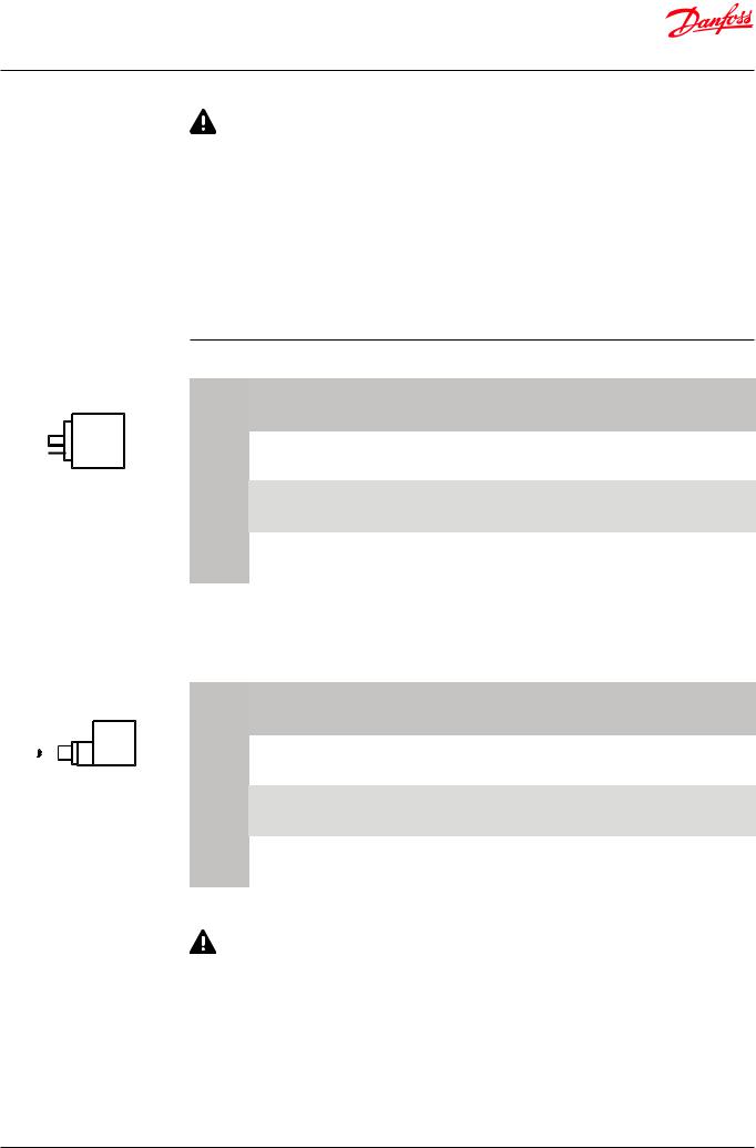
DIN spade connection
Single pack
1 product in a box with installation guide
Multi pack
box with x pieces single pack (can be split)
Industrial pack
x pieces in one box (cannot be split)
Alternating current AC - with DIN plug 1) - IP65
|
Ambient |
Supply |
Voltage |
Frequency |
Power |
Industrial pack |
Multi pack |
|||
Type |
Temp. |
voltage |
consumption |
|||||||
|
|
|
||||||||
|
[°C] |
[V] |
variation |
[Hz] |
|
|
|
|
|
|
|
[W] |
[VA] |
Code no. |
Pcs. |
Code no. |
|||||
|
|
|
||||||||
AS024CS |
-40 – 50 |
24 |
-15% – 10% |
50 |
9.5 |
18 |
– |
- |
042N7608 |
|
|
|
|
|
|
||||||
24 |
-15% – 10% |
60 |
7.0 |
14 |
||||||
|
|
|
|
|
||||||
|
|
|
|
|
|
|
|
|
|
|
AS230CS |
-40 – 50 |
230 |
-15% – 10% |
50 |
8.0 |
16 |
– |
- |
042N7601 |
|
|
|
|
|
|
||||||
208 – 240 |
-15% – 10% |
60 |
7.0 |
14 |
||||||
|
|
|
|
|
||||||
|
|
|
|
|
|
|
|
|
|
|
AS240CS |
-40 – 50 |
240 |
-15% – 10% |
50 |
6.5 |
13 |
– |
- |
042N7602 |
|
|
|
|
|
|
||||||
240 |
-15% – 10% |
60 |
5.0 |
10 |
||||||
|
|
|
|
|
||||||
|
|
|
|
|
|
|
|
|
|
|
1) The three pins on the coil can be fitted with spade tabs, 6.3 mm wide (to DIN 46247). The two current carrying pins can also be fitted with spade tabs, 4.8. mm wide. Max. lead cross section: 1.5 mm2. If DIN plug is used (DIN 43650) the leads must be connected in the socket. The socket is fitted with a Pg 11 screwed entry for 6 – 12 mm.
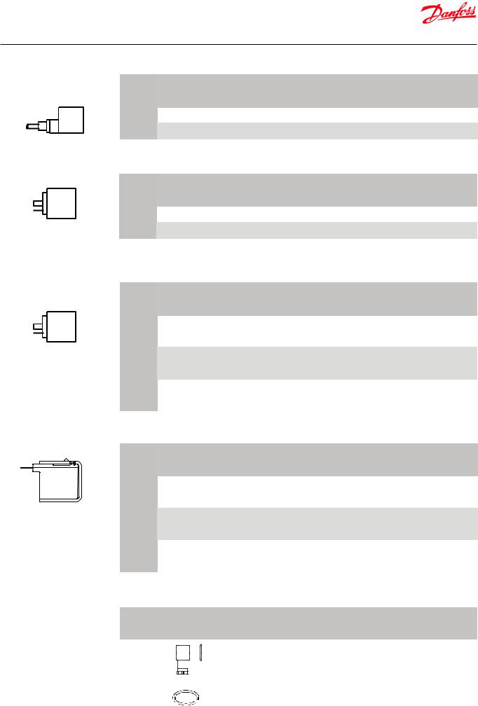
Cable connection |
Alternating current AC with 1 m cable - IP67 |
|
|
|
|
|
|
||||||
|
Ambient |
Supply |
Voltage |
Frequency |
Power |
Industrial pack |
Multi pack |
||||||
|
|
|
|
||||||||||
|
|
|
Type |
Temp. |
voltage |
consumption |
|||||||
|
|
|
|
|
|
||||||||
|
|
|
|
[°C] |
[V] |
variation |
[Hz] |
|
|
|
|
|
|
|
|
|
|
[W] |
[VA] |
Code no. |
Pcs. |
Code no. |
|||||
|
|
|
|
|
|
||||||||
|
|
|
AU115CS |
-40 – 50 |
115 |
-15% – 10% |
50 |
7.0 |
14 |
– |
- |
042N7662 |
|
|
|
|
|||||||||||
|
|
|
|
|
|
|
|
||||||
|
|
|
|
|
|
|
|
||||||
|
|
|
115 |
-15% – 10% |
60 |
5.0 |
10 |
||||||
|
|
|
|
|
|
|
|
||||||
|
|
|
|
|
|
|
|
|
|
|
|
|
|
|
|
|
AU230CS |
-40 – 50 |
230 |
-15% – 10% |
50 |
7.0 |
14 |
042N8651 |
20 |
042N7651 |
|
Single pack |
|
|
|
|
|
||||||||
230 |
-15% – 10% |
60 |
5.0 |
10 |
|||||||||
1 product in a box with installation guide |
|
|
|
|
|
||||||||
Multi pack |
|
|
|
|
|
|
|
|
|
|
|||
|
|
|
|
|
|
|
|
|
|
||||
box with x pieces single pack |
|
|
240 |
-15% – 10% |
50 |
6.5 |
13 |
|
|
|
|||
(can be split) |
AU240CS |
-40 – 50 |
|
|
|
|
|
042N8652 |
20 |
– |
|||
|
|
|
|
|
|||||||||
Industrial pack |
|
|
240 |
-15% – 10% |
60 |
5.0 |
10 |
|
|
|
|||
x pieces in one box (cannot be split) |
|
|
|
|
|
|
|
|
|
|
|||
The EVUL coil (IP65/67) can be applied on systems with R290 as the working fluid.
For countries where safety standards are not an indispensable part of the safety system Danfoss recommend the installer to get a third party approval of the system containing flammable refrigerant.
Note: please follow specific selection criteria stated in the datasheet for these particular refrigerants.
Note: The EVUL coil (IP65/67) has NOT been verified ATEX or IECEx or IEC 60079 series zone 2 compliant. This product is only validated for systems in compliance with ISO5149, IEC 60335 (ref. IEC/EN 60079-15). It is the responsibility of the user to verify such compliance. Improper use can cause explosion, fire, leakage potentially causing death, personal injury, or damage to property.
© Danfoss | DCS (az) | 2017.12 |
DKRCC.PD.BD0.C8.02 | 5 |
Data sheet | Solenoid valves, Type EVUL
Ordering coils
(continued)
Cable connection
DIN spade connection
DIN spade (UL recognized version) connection
Direct current DC with 1 m cable IP67
|
Ambient |
Supply |
Voltage |
Frequency |
Power |
Industrial pack |
Multi pack |
|||
Type |
Temp. |
voltage |
consumption |
|||||||
variation |
[Hz] |
|
|
|
||||||
|
[°C] |
[V] |
[W] |
[VA] |
Code no. |
Pcs. |
Code no. |
|||
|
|
|
||||||||
AU012DS |
-40 – 50 |
12 |
±10% |
DC |
12 |
– |
042N8696 |
20 |
042N7696 |
|
|
|
|
|
|
|
|
|
|
|
|
AU024DS |
-40 – 50 |
24 |
±10% |
DC |
14 |
– |
042N8697 |
20 |
042N7697 |
|
|
|
|
|
|
|
|
|
|
|
|
Direct current DC with DIN spade IP00
|
Ambient |
Supply |
Voltage |
Frequency |
Power |
Industrial pack |
Multi pack |
|||
Type |
Temp. |
voltage |
consumption |
|||||||
variation |
[Hz] |
|
|
|
||||||
|
[°C] |
[V] |
[W] |
[VA] |
Code no. |
Pcs. |
Code no. |
|||
|
|
|
||||||||
AS012DS |
-40 – 60 |
12 |
±10% |
DC |
14 |
– |
042N8686 |
40 |
– |
|
|
|
|
|
|
|
|
|
|
|
|
AS024D |
-40 – 50 |
24 |
±10% |
DC |
14 |
– |
042N8687 |
40 |
042N7687 |
|
|
|
|
|
|
|
|
|
|
|
|
DC coils with 0.25 in. US spade can be supplied on request.
Alternating current AC with DIN spade (UL recognized version) IP00
|
Ambient |
Supply |
Voltage |
Frequency |
Power |
Industrial pack |
Multi pack |
|||
Type |
Temp. |
voltage |
consumption |
|||||||
|
|
|
||||||||
|
[°C] |
[V] |
variation |
[Hz] |
|
|
|
|
|
|
|
[W] |
[VA] |
Code no. |
Pcs. |
Code no. |
|||||
|
|
|
||||||||
AZ240CS |
-40 – 50 |
230 |
-15% – 10% |
50 |
8.0 |
16 |
042N8201 |
40 |
042N4201 |
|
|
|
|
|
|
||||||
208 – 240 |
-15% – 10% |
60 |
7.0 |
14 |
||||||
|
|
|
|
|
||||||
|
|
|
|
|
|
|
|
|
|
|
AZ120CS |
-40 – 50 |
115 |
-15% – 10% |
50 |
8.5 |
16 |
042N8202 |
40 |
042N4202 |
|
|
|
|
|
|
||||||
110 – 120 |
-15% – 10% |
60 |
7.0 |
14 |
||||||
|
|
|
|
|
||||||
|
|
|
|
|
|
|
|
|
|
|
AZ024CS |
-40 – 50 |
24 |
-15% – 10% |
50 |
9.5 |
18 |
042N8203 |
40 |
042N4203 |
|
|
|
|
|
|
||||||
24 |
-15% – 10% |
60 |
7.0 |
14 |
||||||
|
|
|
|
|
||||||
|
|
|
|
|
|
|
|
|
|
|
Alternating current AC with US spade IP00
0.25 in. US spade connections |
|
Ambient |
Supply |
Voltage |
Frequency |
Power |
Industrial pack |
Multi pack |
||||||||||||||
|
|
|
|
|||||||||||||||||||
|
|
|
Type |
Temp. |
voltage |
consumption |
||||||||||||||||
|
|
|
|
|
|
|
|
|
||||||||||||||
|
|
|
|
[°C] |
[V] |
variation |
[Hz] |
|
|
|
|
|
|
|
|
|
||||||
|
|
|
|
[W] |
|
[VA] |
Code no. |
|
Pcs. |
Code no. |
||||||||||||
|
|
|
|
|
|
|
|
|
||||||||||||||
|
|
|
|
|
|
|
||||||||||||||||
|
|
|
AY240C |
-40 – 50 |
208 – 240 |
-15% – 10% |
50 |
8.0 |
|
16 |
042N8230 |
|
40 |
042N4230 |
||||||||
|
|
|
|
|
|
|
|
|
|
|
||||||||||||
|
|
|
208 – 240 |
-15% – 10% |
60 |
8.0 |
|
16 |
||||||||||||||
|
|
|
|
|
|
|
|
|
|
|
|
|
|
|
|
|
||||||
|
|
|
|
|
|
|
|
|
|
|
|
|
|
|
|
|
|
|
|
|
|
|
|
|
|
AY120C |
-40 – 50 |
110 – 120 |
-15% – 10% |
50 |
8.0 |
|
16 |
042N8233 |
|
40 |
042N4233 |
||||||||
Single pack |
|
|
|
|
|
|
|
|
||||||||||||||
110 – 120 |
-15% – 10% |
60 |
8.0 |
|
16 |
|||||||||||||||||
1 product in a box with installation guide |
|
|
|
|
|
|
|
|
|
|
|
|
|
|
||||||||
Multi pack |
|
|
|
|
|
|
|
|
|
|
|
|
|
|
|
|
|
|
|
|
||
|
|
|
|
|
|
|
|
|
|
|
|
|
|
|
|
|
|
|
|
|||
box with x pieces single pack |
|
|
|
|
|
|
|
24 |
-15% – 10% |
50 |
8.0 |
|
16 |
|
|
|
|
|
|
|||
(can be split) |
AY024C |
-40 – 50 |
|
|
|
|
|
|
|
042N8236 |
|
40 |
|
– |
|
|||||||
|
|
|
|
|
|
|
|
|
||||||||||||||
Industrial pack |
|
|
|
|
|
|
|
24 |
-15% – 10% |
60 |
8.0 |
|
16 |
|
|
|
|
|
|
|||
x pieces in one box (cannot be split) |
|
|
|
|
|
|
|
|
|
|
|
|
|
|
|
|
|
|
|
|
||
|
|
|
|
|
|
|
|
|
|
|
|
|
|
|
|
|
|
|
|
|
|
|
Accessories |
|
|
|
|
|
|
|
|
|
|
|
|
|
|
|
|
|
|
|
|
||
|
|
|
|
Part |
|
|
|
Description |
|
|
Multi pack |
|
||||||||||
|
|
|
|
|
|
|
|
|
|
|
|
|
||||||||||
|
|
|
|
|
|
|
|
|
|
|
|
|
|
|
|
|||||||
|
|
|
|
|
|
|
|
|
|
|
|
Code no. |
|
Pcs. |
||||||||
|
|
|
|
|
|
|
|
|
|
|
|
|
|
|
|
|
|
|
|
|||
|
|
|
|
|
|
|
|
|
|
|
|
|
|
|
|
|
|
|
|
|
|
|
|
|
|
|
|
|
|
|
|
|
|
|
DIN plug |
|
|
|
|
|
042N0156 |
|
100 |
||
|
|
|
|
|
|
|
|
|
|
|
|
|
|
|
|
|
|
|||||
|
|
|
|
|
|
|
|
|
|
|
|
|
|
|
||||||||
|
|
|
|
|
|
|
|
|
|
|
|
|
|
|
|
|
|
|
|
|
|
|
|
|
|
|
|
|
|
|
|
|
|
|
O-ring for sealing the coil. |
|
|
|
|
|
|
||||
|
|
|
|
|
|
|
|
|
|
|
|
Industrial pack (50 pcs.) |
|
|
|
032F6115 |
|
125 |
||||
|
|
|
|
|
|
|
|
|
|
|
|
NB: |
|
|
|
|
|
|
||||
|
|
|
|
|
|
|
|
|
|
|
|
|
|
|
|
|
|
|
|
|
||
|
|
|
|
|
|
|
|
|
|
|
|
Valve body suppplied with O-ring |
|
|
|
|
|
|||||
|
|
|
|
|
|
|
|
|
|
|
|
|
|
|
|
|
|
|
|
|
|
|
© Danfoss | DCS (az) | 2017.12 |
DKRCC.PD.BD0.C8.02 | 6 |

Data sheet | Solenoid valves, Type EVUL |
|
|
|
|
|
|
|
|
|
|
|
|
|
|
|
|
|
|
|
|
|
Capacity |
|
|
|
|
|
|
|
|
SI Units |
|
Liquid capacity Qe [kW] |
|
|
|
|
|
|
|
|
|
|
|
KV |
|
|
Liquid capacity Qe [kW] |
|
|
|
|||
|
|
|
|
|
|
|
||||
|
Type |
|
at pressure drop across valve ∆p [bar] |
|
|
|||||
|
[m³ / h] |
|
|
|
||||||
|
|
0.1 |
0.2 |
|
0.3 |
|
0.4 |
|
0.5 |
|
|
|
|
|
|
|
|||||
|
|
|
|
|
|
|
|
|
R22/R407C |
|
|
EVUL 1 |
0.10 |
1.6 |
2.2 |
|
2.7 |
|
3.1 |
|
3.5 |
|
EVUL 2 |
0.20 |
3.1 |
4.4 |
|
5.4 |
|
6.3 |
|
7.0 |
|
EVUL 3 |
0.30 |
4.7 |
6.7 |
|
8.1 |
|
9.4 |
|
10.5 |
|
EVUL 4 |
0.50 |
7.8 |
11.1 |
|
13.6 |
|
15.7 |
|
17.5 |
|
EVUL 5 |
0.65 |
10.2 |
14.4 |
|
17.6 |
|
20.4 |
|
22.8 |
|
EVUL 6 |
0.75 |
11.8 |
16.6 |
|
20.4 |
|
23.5 |
|
26.3 |
|
EVUL 8 |
0.90 |
14.1 |
20.0 |
|
24.4 |
|
28.2 |
|
31.5 |
|
|
|
|
|
|
|
|
|
|
R134a |
|
EVUL 1 |
0.10 |
1.52 |
2.15 |
|
2.63 |
|
3.04 |
|
3.40 |
|
EVUL 2 |
0.20 |
3.04 |
4.30 |
|
5.27 |
|
6.08 |
|
6.80 |
|
EVUL 3 |
0.30 |
4.56 |
6.45 |
|
7.90 |
|
9.12 |
|
10.20 |
|
EVUL 4 |
0.50 |
7.60 |
10.75 |
|
13.17 |
|
15.20 |
|
17.00 |
|
EVUL 5 |
0.65 |
9.88 |
13.98 |
|
17.12 |
|
19.76 |
|
22.10 |
|
EVUL 6 |
0.75 |
11.40 |
16.13 |
|
19.75 |
|
22.81 |
|
25.50 |
|
EVUL 8 |
0.90 |
13.68 |
19.35 |
|
23.70 |
|
27.37 |
|
30.60 |
|
|
|
|
|
|
|
|
|
R404A/R507 |
|
|
EVUL 1 |
0.10 |
1.1 |
1.6 |
|
1.9 |
|
2.2 |
|
2.5 |
|
EVUL 2 |
0.20 |
2.2 |
3.1 |
|
3.9 |
|
4.5 |
|
5.0 |
|
EVUL 3 |
0.30 |
3.3 |
4.7 |
|
5.8 |
|
6.7 |
|
7.5 |
|
EVUL 4 |
0.50 |
5.6 |
7.9 |
|
9.6 |
|
11.1 |
|
12.4 |
|
EVUL 5 |
0.65 |
7.2 |
10.2 |
|
12.5 |
|
14.5 |
|
16.2 |
|
EVUL 6 |
0.75 |
8.3 |
11.8 |
|
14.5 |
|
16.7 |
|
18.7 |
|
EVUL 8 |
0.90 |
10.0 |
14.2 |
|
17.3 |
|
20.0 |
|
22.4 |
|
|
|
|
|
|
|
|
|
|
R410A |
|
EVUL 1 |
0.10 |
1.6 |
2.3 |
|
2.8 |
|
3.2 |
|
3.6 |
|
EVUL 2 |
0.20 |
3.2 |
4.6 |
|
5.6 |
|
6.4 |
|
7.2 |
|
EVUL 3 |
0.30 |
4.8 |
6.8 |
|
8.4 |
|
9.7 |
|
10.8 |
|
EVUL 4 |
0.50 |
8.1 |
11.4 |
|
14.0 |
|
16.1 |
|
18.0 |
|
EVUL 5 |
0.65 |
10.5 |
14.8 |
|
18.1 |
|
20.9 |
|
23.4 |
|
EVUL 6 |
0.75 |
12.1 |
17.1 |
|
20.9 |
|
24.2 |
|
27.0 |
|
EVUL 8 |
0.90 |
14.5 |
20.5 |
|
25.1 |
|
29.0 |
|
32.4 |
|
|
|
|
|
|
|
|
|
|
R290 |
|
EVUL 1 |
0.10 |
1.8 |
2.6 |
|
3.2 |
|
3.7 |
|
4.1 |
|
EVUL 2 |
0.20 |
3.7 |
5.2 |
|
6.3 |
|
7.3 |
|
8.2 |
|
EVUL 3 |
0.30 |
5.5 |
7.8 |
|
9.5 |
|
11.0 |
|
12.3 |
|
EVUL 4 |
0.50 |
9.1 |
12.9 |
|
15.8 |
|
18.3 |
|
20.4 |
|
EVUL 5 |
0.65 |
11.9 |
16.8 |
|
20.6 |
|
23.8 |
|
26.6 |
|
EVUL 6 |
0.75 |
13.7 |
19.4 |
|
23.7 |
|
27.4 |
|
30.7 |
|
EVUL 8 |
0.90 |
16.5 |
23.3 |
|
28.5 |
|
32.9 |
|
36.8 |
Capacities are based on:
-liquid temperature tl = 25 °C ahead of valve,
-evaporating temperature te= -10 °C,
-superheat: 0 K.
Correction factors for liquid temperature tl
tl [°C] |
-10 |
0 |
10 |
15 |
20 |
25 |
30 |
35 |
40 |
45 |
50 |
|
|
|
|
|
|
|
|
|
|
|
|
R22/R407C |
0.76 |
0.82 |
0.88 |
0.92 |
0.96 |
1.00 |
1.05 |
1.10 |
1.16 |
1.22 |
1.30 |
R134a |
0.73 |
0.79 |
0.86 |
0.90 |
0.95 |
1.00 |
1.06 |
1.12 |
1.19 |
1.27 |
1.37 |
R404A/507 |
0.65 |
0.72 |
0.81 |
0.86 |
0.93 |
1.00 |
1.09 |
1.20 |
1.33 |
1.51 |
1.74 |
R410A |
0.73 |
0.79 |
0.86 |
0.90 |
0.95 |
1.00 |
1.06 |
1.14 |
1.23 |
1.33 |
1.47 |
R290 |
0.74 |
0.79 |
0.86 |
0.90 |
0.95 |
1.00 |
1.05 |
1.12 |
1.19 |
1.28 |
1.36 |
|
When sizing valves, the plant capacity must be multiplied by a correction factor depending on liquid |
|
temperature tl ahead of valve / evaporator. When the corrected capacity is known, the selection can be |
|
made from the table. |
|
|
© Danfoss | DCS (az) | 2017.12 |
DKRCC.PD.BD0.C8.02 | 7 |

Data sheet | Solenoid valves, Type EVUL |
|
|
|
|
|
|
|
|
|
|
|
|
|
|
|
|
|
|
|
Capacity |
|
|
|
|
|
|
|
SI Units |
|
Suction vapour |
|
|
|
|
|
|
|
|
|
capacity Qe [kW] |
|
KV |
Pressure |
|
Suction vapour capacity Qe [kW] |
|
|||
|
|
|
at Evaporating temperature te [°C] |
|
|||||
|
Type |
drop ∆p |
|
|
|||||
|
[m³ / h] |
|
|
||||||
|
|
|
|
|
|
|
|||
|
|
[bar] |
|
|
|
|
|
|
|
|
|
|
-40 |
-30 |
-20 |
-10 |
0 |
10 |
|
|
|
|
|
||||||
|
|
|
|
|
|
|
|
|
|
|
|
|
|
|
|
|
|
R22/R407C |
|
|
|
|
0.1 |
0.077 |
0.104 |
0.134 |
0.170 |
0.210 |
0.255 |
|
EVUL 1 |
|
|
|
|
|
|
|
|
|
0.10 |
0.15 |
0.090 |
0.124 |
0.162 |
0.206 |
0.255 |
0.311 |
|
|
|
|
|
|
|
|
|
|
|
|
|
|
0.2 |
0.100 |
0.139 |
0.184 |
0.235 |
0.293 |
0.357 |
|
|
|
|
|
|
|
|
|
|
|
|
|
0.1 |
0.154 |
0.207 |
0.269 |
0.339 |
0.419 |
0.510 |
|
EVUL 2 |
|
|
|
|
|
|
|
|
|
0.20 |
0.15 |
0.181 |
0.248 |
0.324 |
0.411 |
0.510 |
0.622 |
|
|
|
|
|
|
|
|
|
|
|
|
|
|
0.2 |
0.199 |
0.279 |
0.368 |
0.470 |
0.585 |
0.715 |
|
|
|
|
|
|
|
|
|
|
|
|
|
0.1 |
0.231 |
0.311 |
0.403 |
0.509 |
0.629 |
0.765 |
|
EVUL 3 |
|
|
|
|
|
|
|
|
|
0.30 |
0.15 |
0.271 |
0.372 |
0.486 |
0.617 |
0.765 |
0.933 |
|
|
|
|
|
|
|
|
|
|
|
|
|
|
0.2 |
0.299 |
0.418 |
0.553 |
0.705 |
0.878 |
1.072 |
|
|
|
|
|
|
|
|
|
|
|
|
|
0.1 |
0.386 |
0.518 |
0.672 |
0.848 |
1.048 |
1.275 |
|
EVUL 4 |
|
|
|
|
|
|
|
|
|
0.50 |
0.15 |
0.452 |
0.619 |
0.810 |
1.028 |
1.275 |
1.555 |
|
|
|
|
|
|
|
|
|
|
|
|
|
|
0.2 |
0.499 |
0.697 |
0.921 |
1.175 |
1.463 |
1.787 |
|
|
|
|
|
|
|
|
|
|
|
|
|
0.1 |
0.501 |
0.674 |
0.873 |
1.102 |
1.363 |
1.658 |
|
EVUL 5 |
|
|
|
|
|
|
|
|
|
0.65 |
0.15 |
0.588 |
0.805 |
1.053 |
1.336 |
1.658 |
2.021 |
|
|
|
|
|
|
|
|
|
|
|
|
|
|
0.2 |
0.648 |
0.906 |
1.197 |
1.528 |
1.901 |
2.323 |
|
|
|
|
|
|
|
|
|
|
|
|
|
0.1 |
0.579 |
0.778 |
1.008 |
1.272 |
1.573 |
1.913 |
|
EVUL 6 |
|
|
|
|
|
|
|
|
|
0.75 |
0.15 |
0.679 |
0.929 |
1.215 |
1.542 |
1.913 |
2.332 |
|
|
|
|
|
|
|
|
|
|
|
|
|
|
0.2 |
0.748 |
1.045 |
1.381 |
1.763 |
2.194 |
2.680 |
|
|
|
|
|
|
|
|
|
|
|
|
|
0.1 |
0.694 |
0.933 |
1.209 |
1.526 |
1.887 |
2.296 |
|
EVUL 8 |
|
|
|
|
|
|
|
|
|
0.90 |
0.15 |
0.814 |
1.115 |
1.458 |
1.850 |
2.296 |
2.798 |
|
|
|
|
|
|
|
|
|
|
|
|
|
|
0.2 |
0.897 |
1.254 |
1.658 |
2.115 |
2.633 |
3.216 |
|
|
|
|
|
|
|
|
|
|
Capacities are based on dry, saturated vapour ahead of valve.
Capacities are based on:
- liquid temperature tl = 25 °C ahead of evaporator.
The table values refer to the evaporator capacity and are given as a function of:
-evaporating temperature te,
-pressure drop Δp in valve.
Correction factors for liquid temperature tl
tl [°C] |
10 |
15 |
20 |
25 |
30 |
35 |
40 |
45 |
50 |
|
|
|
|
|
|
|
|
|
|
R22/R407C |
0.90 |
0.93 |
0.96 |
1.00 |
1.04 |
1.08 |
1.13 |
1.18 |
1.24 |
|
|
|
|
|
|
|
|
|
|
|
When sizing valves, the plant capacity must be multiplied by a correction factor depending on liquid |
|
temperature tl ahead of valve evaporator. When the corrected capacity is known, the selection can be |
|
made from the table. |
|
|
© Danfoss | DCS (az) | 2017.12 |
DKRCC.PD.BD0.C8.02 | 8 |

Data sheet | Solenoid valves, Type EVUL |
|
|
|
|
|
|
|
|
|
|
|
|
|
|
|
|
|
|
|
Capacity |
|
|
|
|
|
|
|
|
SI Units |
Suction vapour |
|
|
|
|
|
|
|
|
|
|
|
|
|
|
|
|
|
|
|
capacity Qe [kW] |
|
|
Pressure |
|
Suction vapour capacity Qe [kW] |
|
|||
(continued) |
|
KV |
|
at Evaporating temperature te [°C] |
|
||||
Type |
drop ∆p |
|
|
||||||
|
[m³ / h] |
|
|
|
|
|
|
||
|
|
[bar] |
|
|
|
|
|
|
|
|
|
|
-40 |
-30 |
-20 |
-10 |
0 |
10 |
|
|
|
|
|
||||||
|
|
|
|
|
|
|
|
|
|
|
|
|
|
|
|
|
|
|
R134a |
|
|
|
|
|
|
|
|
|
|
|
|
|
0.1 |
0.056 |
0.078 |
0.104 |
0.134 |
0.169 |
0.208 |
|
EVUL 1 |
|
|
|
|
|
|
|
|
|
0.10 |
0.15 |
0.062 |
0.091 |
0.124 |
0.162 |
0.204 |
0.253 |
|
|
|
|
|
|
|
|
|
|
|
|
|
|
0.2 |
0.065 |
0.100 |
0.139 |
0.183 |
0.233 |
0.290 |
|
|
|
|
|
|
|
|
|
|
|
|
|
0.1 |
0.111 |
0.156 |
0.208 |
0.268 |
0.338 |
0.417 |
|
EVUL 2 |
|
|
|
|
|
|
|
|
|
0.20 |
0.15 |
0.125 |
0.182 |
0.248 |
0.323 |
0.409 |
0.507 |
|
|
|
|
|
|
|
|
|
|
|
|
|
|
0.2 |
0.130 |
0.201 |
0.278 |
0.366 |
0.467 |
0.580 |
|
|
|
|
|
|
|
|
|
|
|
|
|
0.1 |
0.167 |
0.234 |
0.312 |
0.402 |
0.506 |
0.625 |
|
EVUL 3 |
|
|
|
|
|
|
|
|
|
0.30 |
0.15 |
0.187 |
0.274 |
0.372 |
0.485 |
0.613 |
0.760 |
|
|
|
|
|
|
|
|
|
|
|
|
|
|
0.2 |
0.196 |
0.301 |
0.417 |
0.550 |
0.700 |
0.871 |
|
|
|
|
|
|
|
|
|
|
|
|
|
0.1 |
0.278 |
0.390 |
0.520 |
0.671 |
0.844 |
1.042 |
|
EVUL 4 |
|
|
|
|
|
|
|
|
|
0.50 |
0.15 |
0.312 |
0.456 |
0.620 |
0.808 |
1.022 |
1.267 |
|
|
|
|
|
|
|
|
|
|
|
|
|
|
0.2 |
0.326 |
0.501 |
0.696 |
0.916 |
1.167 |
1.451 |
|
|
|
|
|
|
|
|
|
|
|
|
|
0.1 |
0.361 |
0.507 |
0.676 |
0.872 |
1.097 |
1.355 |
|
EVUL 5 |
|
|
|
|
|
|
|
|
|
0.65 |
0.15 |
0.405 |
0.593 |
0.806 |
1.050 |
1.329 |
1.646 |
|
|
|
|
|
|
|
|
|
|
|
|
|
|
0.2 |
0.424 |
0.652 |
0.905 |
1.191 |
1.517 |
1.886 |
|
|
|
|
|
|
|
|
|
|
|
|
|
0.1 |
0.416 |
0.585 |
0.780 |
1.006 |
1.266 |
1.563 |
|
EVUL 6 |
|
|
|
|
|
|
|
|
|
0.75 |
0.15 |
0.468 |
0.684 |
0.930 |
1.211 |
1.533 |
1.900 |
|
|
|
|
|
|
|
|
|
|
|
|
|
|
0.2 |
0.489 |
0.752 |
1.044 |
1.374 |
1.750 |
2.176 |
|
|
|
|
|
|
|
|
|
|
|
|
|
0.1 |
0.500 |
0.702 |
0.936 |
1.207 |
1.519 |
1.876 |
|
EVUL 8 |
|
|
|
|
|
|
|
|
|
0.90 |
0.15 |
0.561 |
0.821 |
1.116 |
1.454 |
1.840 |
2.280 |
|
|
|
|
|
|
|
|
|
|
|
|
|
|
0.2 |
0.587 |
0.902 |
1.252 |
1.649 |
2.100 |
2.612 |
|
|
|
|
|
|
|
|
|
|
Capacities are based on dry, saturated vapour ahead of valve.
Capacities are based on:
- liquid temperature tl = 25 °C ahead of evaporator.
The table values refer to the evaporator capacity and are given as a function of:
-evaporating temperature te,
-pressure drop Δp in valve.
Correction factors for liquid temperature tl
tl [°C] |
10 |
15 |
20 |
25 |
30 |
35 |
40 |
45 |
50 |
|
|
|
|
|
|
|
|
|
|
R134a |
0.88 |
0.92 |
0.96 |
1.00 |
1.05 |
1.10 |
1.16 |
1.23 |
1.31 |
|
|
|
|
|
|
|
|
|
|
|
When sizing valves, the plant capacity must be multiplied by a correction factor depending on liquid |
|
temperature tl ahead of valve evaporator. When the corrected capacity is known, the selection can be |
|
made from the table. |
|
|
© Danfoss | DCS (az) | 2017.12 |
DKRCC.PD.BD0.C8.02 | 9 |

Data sheet | Solenoid valves, Type EVUL
Capacity |
|
|
|
|
|
|
|
|
SI Units |
Suction vapour |
|
|
|
|
|
|
|
|
|
capacity Qe [kW] |
|
|
Pressure |
|
Suction vapour capacity Qe [kW] |
|
|||
(continued) |
|
KV |
|
|
|||||
|
|
at Evaporating temperature te [°C] |
|
||||||
Type |
drop ∆p |
|
|
||||||
|
[m³ / h] |
|
|
||||||
|
|
|
|
|
|
|
|||
|
|
[bar] |
|
|
|
|
|
|
|
|
|
|
-40 |
-30 |
-20 |
-10 |
0 |
10 |
|
|
|
|
|
||||||
|
|
|
|
|
|
|
|
|
|
|
|
|
|
|
|
|
|
R404A/R507 |
|
|
|
|
0.1 |
0.075 |
0.099 |
0.127 |
0.159 |
0.196 |
0.239 |
|
EVUL 1 |
|
|
|
|
|
|
|
|
|
0.10 |
0.15 |
0.089 |
0.119 |
0.154 |
0.194 |
0.239 |
0.291 |
|
|
|
|
|
|
|
|
|
|
|
|
|
|
0.2 |
0.100 |
0.135 |
0.176 |
0.222 |
0.275 |
0.335 |
|
|
|
|
|
|
|
|
|
|
|
|
|
0.1 |
0.150 |
0.198 |
0.254 |
0.319 |
0.393 |
0.477 |
|
EVUL 2 |
|
|
|
|
|
|
|
|
|
0.20 |
0.15 |
0.179 |
0.239 |
0.308 |
0.388 |
0.479 |
0.583 |
|
|
|
|
|
|
|
|
|
|
|
|
|
|
0.2 |
0.201 |
0.271 |
0.352 |
0.444 |
0.550 |
0.670 |
|
|
|
|
|
|
|
|
|
|
|
|
|
0.1 |
0.225 |
0.297 |
0.381 |
0.478 |
0.589 |
0.716 |
|
EVUL 3 |
|
|
|
|
|
|
|
|
|
0.30 |
0.15 |
0.268 |
0.358 |
0.462 |
0.581 |
0.718 |
0.874 |
|
|
|
|
|
|
|
|
|
|
|
|
|
|
0.2 |
0.301 |
0.406 |
0.527 |
0.666 |
0.825 |
1.005 |
|
|
|
|
|
|
|
|
|
|
|
|
|
0.1 |
0.375 |
0.495 |
0.635 |
0.797 |
0.982 |
1.194 |
|
EVUL 4 |
|
|
|
|
|
|
|
|
|
0.50 |
0.15 |
0.447 |
0.596 |
0.769 |
0.969 |
1.197 |
1.457 |
|
|
|
|
|
|
|
|
|
|
|
|
|
|
0.2 |
0.502 |
0.677 |
0.879 |
1.110 |
1.375 |
1.676 |
|
|
|
|
|
|
|
|
|
|
|
|
|
0.1 |
0.488 |
0.644 |
0.826 |
1.036 |
1.277 |
1.552 |
|
EVUL 5 |
|
|
|
|
|
|
|
|
|
0.65 |
0.15 |
0.582 |
0.775 |
1.000 |
1.260 |
1.556 |
1.893 |
|
|
|
|
|
|
|
|
|
|
|
|
|
|
0.2 |
0.653 |
0.880 |
1.142 |
1.444 |
1.788 |
2.178 |
|
|
|
|
|
|
|
|
|
|
|
|
|
0.1 |
0.563 |
0.743 |
0.953 |
1.195 |
1.474 |
1.790 |
|
EVUL 6 |
|
|
|
|
|
|
|
|
|
0.75 |
0.15 |
0.671 |
0.895 |
1.154 |
1.453 |
1.796 |
2.185 |
|
|
|
|
|
|
|
|
|
|
|
|
|
|
0.2 |
0.754 |
1.016 |
1.318 |
1.666 |
2.063 |
2.514 |
|
|
|
|
|
|
|
|
|
|
|
|
|
0.1 |
0.675 |
0.891 |
1.143 |
1.434 |
1.768 |
2.148 |
|
EVUL 8 |
|
|
|
|
|
|
|
|
|
0.90 |
0.15 |
0.805 |
1.074 |
1.385 |
1.744 |
2.155 |
2.622 |
|
|
|
|
|
|
|
|
|
|
|
|
|
|
0.2 |
0.904 |
1.219 |
1.582 |
1.999 |
2.475 |
3.016 |
|
|
|
|
|
|
|
|
|
|
Capacities are based on dry, saturated vapour ahead of valve.
During operation with superheated vapour ahead of valve, the capacities are reduced by 4% for each 10 K superheat.
Capacities are based on:
- liquid temperature tl = 25 °C ahead of evaporator.
The table values refer to the evaporator capacity and are given as a function of:
-evaporating temperature te,
-pressure drop Δp in valve.
Correction factors for liquid temperature tl
tl [°C] |
10 |
15 |
20 |
25 |
30 |
35 |
40 |
45 |
50 |
|
|
|
|
|
|
|
|
|
|
R404A/R507 |
0.84 |
0.89 |
0.94 |
1.00 |
1.07 |
1.16 |
1.26 |
1.40 |
1.57 |
|
|
|
|
|
|
|
|
|
|
|
When sizing valves, the plant capacity must be multiplied by a correction factor depending on liquid |
|
temperature tl ahead of valve evaporator. When the corrected capacity is known, the selection can be |
|
made from the table. |
|
|
© Danfoss | DCS (az) | 2017.12 |
DKRCC.PD.BD0.C8.02 | 10 |
 Loading...