


Danfoss EVR 2 NC, EVR 3 NC, EVR 4 NC, EVR 6 NC, EVR 6 NO Data sheet
...Data Sheet
Solenoid valve
Type EVR 2 - EVR 40
Version 2
EVR is a direct or servo operated solenoid valve suitable for liquid, suction, and hot gas lines with most refrigerants, including €ammable refrigerants.
EVR valves and coils are sold separately.
Features
• Complete range of solenoid valves for refrigeration, freezing and air conditioning plant
• Supplied in versions normally closed (NC) and normally open (NO) with de-energized coil
• Wide choice of coils for AC and DC
• Suitable for most refrigerants, including €ammable refrigerants
• Designed for media temperatures up to 105 °C
• Flare connections up to 5⁄8 in
• Solder connections up to 2 1⁄8 in
• Extended ends on solder versions make the installation easy, eliminating the need to dismantle the valve when soldering in
• Available in €are, solder and €ange connection versions
AI249086497583en-001301

Solenoid valve, Type EVR 2 - EVR 40
Functions
Function
EVR solenoid valves are designed on two di„erent principles:
1.Direct operation
2.Servo operation
1. Direct operation (NC)
EVR 2 – EVR 3 are direct operated. The valves open directly for full €ow when the armature (3) moves up into the magnetic †eld of the coil.
This means that the valves operate with a minimum di„erential pressure of 0 bar. The seat plate is †tted directly on the armature (3) see Design and material.
Inlet pressure acts from above on the armature and the valve plate. Thus, the inlet pressure and spring force act to close the valve when there is no current in the coil.
2. Servo operation (NC)
EVR 4 – EVR 22 are servo operated with a "€oating" diaphragm (4) see Design and material. The pilot ori†ce of stainless steel is placed in the center of the diaphragm. The seat plate is †tted directly to the armature (3) see Design and material. When there is no current in the coil, the main ori†ce and pilot ori†ce are closed. The pilot ori†ce and main ori†ce are held closed by the armature spring force and the di„erential pressure between inlet and
outlet sides.
When current is applied to the coil, the armature is drawn up into the magnetic †eld and opens the pilot ori†ce. This relieves the pressure above the diaphragm, i.e. the space above the diaphragm becomes connected to the outlet side of the valve.
The di„erential pressure between inlet and outlet sides then presses the diaphragm away from the main ori†ce and opens it for full €ow. Therefore a certain minimum di„erential pressure is necessary to open the valve and keep it open. For EVR 4 – EVR 22 valves the minimum di„erential pressure for safe operation is 0.03 bar.
When the current is switched o„, the pilot ori†ce is closed. Via the equalization holes in the diaphragm, the pressure above the diaphragm rises to the same value as the inlet pressure and the diaphragm closes the main ori†ce.
EVR 25, EVR 32 and EVR 40 are servo operated piston valves. The servo piston (16) see Design and material with sealing face closes against the valve seat by means of the di„erential pressure between inlet and outlet side of the valve and the force of the compression spring. When the coil is switched on, the pilot ori†ce opens. This relieves the pressure on the piston spring side of the valve. The di„erential pressure will then open the valve. The minimum di„erential pressure for safe operation is 0.2 bar.
EVR (NO) has the opposite function to EVR (NC), i.e. it is open with de-energized coil. EVR (NO) is available with servo operation only.
2.1. Bi-flow operation
Bi-€ow operation with EVRC EVRC is a servo operated solenoid valve with a special diaphragm with built-in nonreturn valve. The valve is for use in liquid lines in refrigeration plants.
EVRC allows €ow in both directions and can be used in liquid lines in refrigeration plants with hot gas or gas defrost.
During the refrigeration period EVRC works as a normal solenoid valve, while during defrost it allows the condensed liquid to return to the liquid manifold.
During the defrosting period the coil for EVRC must be energized.
2.2. Manual stem operation for EVR 6 - EVR 25 NC
EVR 6 - EVR 25 NC are available with optional manual stem operation to manually force the NC valve open when the coil is de-energized.
© Danfoss | Climate Solutions | 2021.02 |
AI249086497583en-001301 | 2 |

Solenoid valve, Type EVR 2 - EVR 40
The protective cap should be removed and the manual stem (12) Design and material should be rotated until the valve is fully open. It takes approx. 6 cycles from fully closed, to reach the fully open position.
After manual operation is completed, the valve should manually be closed again and the protective cap mounted.
NOTE:
Alternatively, all EVR NC and NO valves can be manually operated by removing the coil and force the valve open or closed by using a solenoid valve tester (permanent magnet) code no. 018F0091.
© Danfoss | Climate Solutions | 2021.02 |
AI249086497583en-001301 | 3 |

Solenoid valve, Type EVR 2 - EVR 40
Media
Refrigerants
R1234yf, R1234ze(E), R125, R134a, R152a, R22, R290, R32, R404A, R407C, R407F, R407H, R410A, R413A, R417A, R422A, R422B, R422D, R438A, R422A, R422B, R422D, R438A, R442A, R444B, R447A, R447B, R448A, R449A, R449B, R450A, R452A, R452B, R454A, R454B, R454C, R455A, R463A, R507A, R512A, R513A, R513B, R515A, R515B, R516A, R600, R600a.
For a complete list of approved refrigerants, visit store.danfoss.com and search for individual code numbers, where refrigerants are listed as part of technical data.
NOTE:
Special note for R1234yf, R1234ze, R152A, R290, R32, R444B, R452B, R454A, R454B, R454C, R455A, R516A, R600 and R600a: This product is validated in accordance to ATEX, ISO 5149, IEC 60335-2-24, IEC 60335-2-40 and UL. Ignition risk is evaluated in accordance to ISO 5149 and IEC 60335.
The EVR 2 – EVR 22 with solder connections and without manual stem can be applied on systems with R1234yf, R1234ze, R152A, R290, R32, R444B, R452B, R454A, R454B, R454C, R455A, R516A, R600 and R600a as the working €uid.
EVR 2-15 €are connections are only approved for A1 and A2L refrigerants
NOTE:
Excluded from this EVR 22 with connections 1 3⁄8 inch / 35mm related to PED requirements.
The EVR 2-EVR 40 versions with solder and €are connection and without manual stem can be applied to oil-free systems : R1234ze(E)
EVR 2 - EVR 22 versions with solder and €are connections and without manual stem can be applied to oil-free systems R513A, R515B, R516A
NOTE:
EVR 2-22 (R516A) and EVR 2-40, R1234ze:
•Excluded from this EVR 22 - EVR 40 with connections 1 3⁄8 inch / 35mm and larger connections related to higher PED requirements.
For countries where safety standards are not an indispensable part of the safety system Danfoss recommends the installer gets a third party approval of any system containing €ammable refrigerant.
NOTE:
Please follow speci†c selection criteria stated in the datasheet for these particular refrigerants.
Media temperature
-40 – 105 °C, Max. 130 °C during defrosting
For R1234ze Media temperature: - 20 - 90 °C (105 °C for transient condition).
© Danfoss | Climate Solutions | 2021.02 |
AI249086497583en-001301 | 4 |
Solenoid valve, Type EVR 2 - EVR 40
Product speci€cation
Technical data
Ambient temperature and enclosure for coil
See separate data sheet for solenoid and ATEX coils.
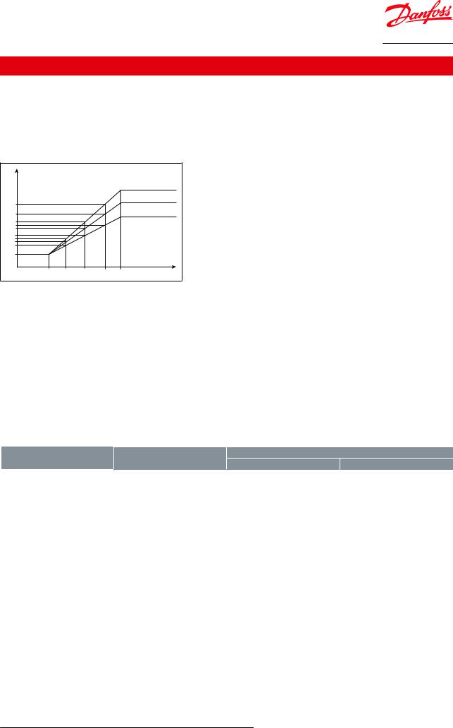
Max. working pressure
Figure 1: Max. working pressure in bar in relation to media temperature in °C.
bar |
|
|
|
|
<![if ! IE]> <![endif]>Danfoss 32f986.02 |
|
|
|
|
|
|
|
|
|
|
|
49 bar |
37.5 |
|
|
|
|
45.2 bar |
|
|
|
|
|
|
34.65 |
|
|
|
|
32 bar |
26 |
|
|
|
|
|
24.75 |
|
|
|
|
|
24.1 |
|
|
|
|
|
17.5 |
|
|
|
|
|
14.5 |
|
|
|
|
|
13.55 |
|
|
|
|
|
10.25 |
|
|
|
|
|
3 |
|
|
|
|
|
-40 |
-30 |
-20 |
-10 |
0 |
°C |
|
|
|
|
|
WARNING:
Special note for EVR PED version: The EVR 2 - EVR 22 versions with solder connections and without manual stem can be applied to 49 bar MWP.
NOTE:
Excluded from this EVR 22 with connections 1 3⁄8 inch / 35 mm related to higher PED requirements.
Capacity
For Kv values refer to the tables in Ordering.
The Kv value of the water €ow in [m3/h] at a pressure drop across valve of 1 bar, ρ = 1000 kg/m3. See extended capacity tables on Coolselector®2.
Table 1: MOPD
|
|
|
Opening differential pressure with standard coil ∆p [bar] |
||
|
Type |
Min. |
|
|
Max. (= MOPD) liquid |
|
|
|
AC coil [10 W] |
DC coil [20 W] |
|
|
|
|
|
||
|
EVR 2 NC |
0.00 |
38 |
33 |
|
|
EVR 3 NC |
0.00 |
38 |
18 |
|
|
EVR 4 NC |
0.03 |
38 |
28 |
|
|
EVR 6 NC |
0.03 |
38 |
28 |
|
|
EVR 6 NO |
0.03 |
21 |
21 |
|
|
EVR 8 NC |
0.03 |
38 |
28 |
|
|
EVR 10 NC |
0.03 |
38 |
20 |
|
|
EVR 10 NO |
0.03 |
21 |
21 |
|
|
EVR 15 NC |
0.03 |
38 |
20 |
|
|
EVR 15 NO |
0.03 |
21 |
21 |
|
|
EVR 18 NC |
0.03 |
38 |
20 |
|
|
EVR 20 NC |
0.03 |
38 |
20 |
|
|
EVR 20 NO |
0.03 |
19 |
19 |
|
|
EVR 22 NC |
0.03 |
38 |
20 |
|
|
EVR 22 NO |
0.03 |
19 |
19 |
|
|
EVR 25 NC |
0.2 |
38 |
17 |
|
|
EVR 32 NC |
0.2 |
38 |
17 |
|
|
EVR 40 NC |
0.2 |
38 |
17 |
|
|
|
|
|
|
|
NOTE:
For higher MODP 12 W and 20 W AC coils are available on request
© Danfoss | Climate Solutions | 2021.02 |
AI249086497583en-001301 | 5 |

Solenoid valve, Type EVR 2 - EVR 40
Valve selection based on capacity calculation
As for extended capacity calculations and valve selection based on capacities and refrigerants, please refer to Coolselector®2. Rated and extended capacities are calculated with the Coolselector®2 calculation engine to ARI standards with the ASEREP equations based on laboratory measurements of selected valves.
Rated capacity [kW]
Table 2: Rated capacity [kW]
Type |
R22/R407C |
R134a |
R404A/R507 |
R410A |
R32 |
R290 |
R600a |
|
|
|
Liquid |
|
|
|
|
EVR 2 |
3.02 |
2.79 |
2.04 |
2.96 |
4.23 |
3.36 |
3.38 |
EVR 3 |
5.43 |
5.02 |
3.68 |
5.32 |
7.61 |
6.05 |
6.09 |
EVR 4 |
13.68 |
12.66 |
9.26 |
13.41 |
19.17 |
15.23 |
15.33 |
EVR 6 |
17.90 |
16.56 |
12.12 |
17.55 |
25.09 |
19.93 |
20.07 |
EVR 8 |
21.32 |
19.73 |
14.44 |
20.90 |
29.88 |
23.74 |
23.90 |
EVR 10 |
37.62 |
34.80 |
25.47 |
36.88 |
52.71 |
41.88 |
42.17 |
EVR 15 |
57.93 |
53.60 |
39.23 |
56.79 |
81.18 |
64.49 |
64.94 |
EVR 18 |
75.84 |
70.16 |
51.36 |
74.35 |
106.26 |
84.43 |
85.01 |
EVR 20 |
120.29 |
111.29 |
81.46 |
117.93 |
168.56 |
133.92 |
134.85 |
EVR 22 |
137.19 |
126.92 |
92.90 |
134.49 |
192.23 |
152.73 |
153.79 |
EVR 25 |
149.23 |
138.06 |
101.06 |
146.30 |
– |
– |
– |
EVR 32 |
254.97 |
235.89 |
172.66 |
249.96 |
– |
– |
– |
EVR 40 |
368.74 |
341.15 |
249.71 |
361.49 |
– |
– |
– |
|
|
|
Suction vapour |
|
|
|
|
EVR 2 |
0.33 |
0.24 |
0.29 |
0.42 |
0.54 |
0.41 |
0.23 |
EVR 3 |
0.60 |
0.44 |
0.52 |
0.75 |
0.96 |
0.73 |
0.41 |
EVR 4 |
1.51 |
1.10 |
1.32 |
1.90 |
2.43 |
1.85 |
1.03 |
EVR 6 |
1.98 |
1.44 |
1.72 |
2.48 |
3.18 |
2.42 |
1.35 |
EVR 8 |
2.35 |
1.71 |
2.05 |
2.96 |
3.78 |
2.88 |
1.60 |
EVR 10 |
4.15 |
3.02 |
3.62 |
5.22 |
6.67 |
5.09 |
2.83 |
EVR 15 |
6.40 |
4.65 |
5.57 |
8.03 |
10.28 |
7.83 |
4.36 |
EVR 18 |
8.37 |
6.09 |
7.30 |
10.52 |
13.45 |
10.26 |
5.70 |
EVR 20 |
13.28 |
9.66 |
11.57 |
16.68 |
21.34 |
16.27 |
9.04 |
EVR 22 |
15.15 |
11.02 |
13.20 |
19.02 |
24.34 |
18.55 |
10.31 |
EVR 25 |
16.33 |
11.79 |
14.25 |
20.58 |
– |
– |
– |
EVR 32 |
27.90 |
20.14 |
24.35 |
35.16 |
– |
– |
– |
EVR 40 |
40.35 |
29.12 |
35.21 |
50.85 |
– |
– |
– |
|
|
|
Hot gas |
|
|
|
|
EVR 2 |
1.35 |
1.04 |
1.10 |
1.65 |
2.18 |
1.54 |
0.94 |
EVR 3 |
2.42 |
1.87 |
1.99 |
2.98 |
3.92 |
2.76 |
1.70 |
EVR 4 |
6.10 |
4.70 |
5.01 |
7.50 |
9.86 |
6.96 |
4.28 |
EVR 6 |
7.99 |
6.16 |
6.56 |
9.81 |
12.91 |
9.11 |
5.61 |
EVR 8 |
9.51 |
7.33 |
7.81 |
11.68 |
15.37 |
10.85 |
6.68 |
EVR 10 |
16.78 |
12.94 |
13.78 |
20.61 |
27.12 |
19.14 |
11.78 |
EVR 15 |
25.85 |
19.93 |
21.22 |
31.74 |
41.77 |
29.48 |
18.14 |
EVR 18 |
33.84 |
26.08 |
27.77 |
41.55 |
54.67 |
38.59 |
23.75 |
EVR 20 |
53.68 |
41.37 |
44.05 |
65.91 |
86.72 |
61.21 |
37.67 |
EVR 22 |
61.22 |
47.18 |
50.24 |
75.17 |
98.91 |
69.81 |
42.96 |
EVR 25 |
87.87 |
67.73 |
72.12 |
107.91 |
– |
– |
– |
EVR 32 |
150.17 |
115.75 |
123.24 |
184.40 |
– |
– |
– |
EVR 40 |
217.22 |
167.43 |
178.27 |
266.74 |
– |
– |
– |
|
|
|
|
|
|
|
|
Rated liquid and suction vapor capacity is based on:
•vaporating temperature te = -10 °C
•liquid temperature ahead of valve tl = 25 °C
•pressure drop in valve ∆p = 0.15 bar
Rated hot gas capacity is based on:
© Danfoss | Climate Solutions | 2021.02 |
AI249086497583en-001301 | 6 |
Solenoid valve, Type EVR 2 - EVR 40
•condensing temperature tc = 40 °C
•pressure drop across valve ∆p = 0.8 bar
•hot gas temperature th = 65 °C
•subcooling of refrigerant ∆tsub = 4 K
For other refrigerants, please refer to Coolselector®2
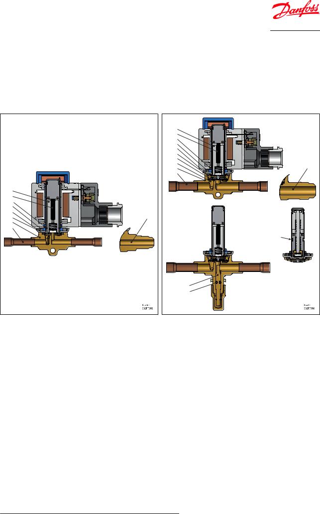
Design and material
Figure 2: EVR 2 - EVR 3 Solder and ‚are connection
3 |
|
6 |
|
9 |
|
8 |
|
7 |
|
2 |
11 |
1 |
|
10 |
|
Figure 3: EVR 4 - EVR 6 - EVR 8 Solder and ‚are connection
3 |
|
6 |
|
9 |
|
8 |
|
7 |
|
2 |
|
4 |
|
5 |
11 |
1 |
|
10 |
|
|
T |
|
12 |
|
13 |
Table 3: Design and material for EVR 2, EVR 3, EVR 4, EVR 6, EVR 8
Pos. no. |
Description |
Material |
1 |
Valve housing assembly |
Brass |
2 |
Cover |
Stainless steel |
3 |
Armature assembly |
Stainless steel/PTFE |
4 |
Diaphragm assembly |
Stainless steel/PTFE |
5 |
Support washer |
Stainless steel |
6 |
Armature spring |
Stainless steel |
7 |
Seal |
Chloroprene rubber |
8 |
Screws |
Stainless steel |
9 |
O-ring |
EPDM rubber |
10 |
Solder connection |
Copper |
11 |
Flare connection |
Brass |
12 |
Manual stem (1) |
Brass |
13 |
O-ring |
Chloroprene rubber |
T |
Normally Open (NO) tube design |
|
|
|
|
(1) Manual stem is not available for EVR 4
© Danfoss | Climate Solutions | 2021.02 |
AI249086497583en-001301 | 7 |
Solenoid valve, Type EVR 2 - EVR 40
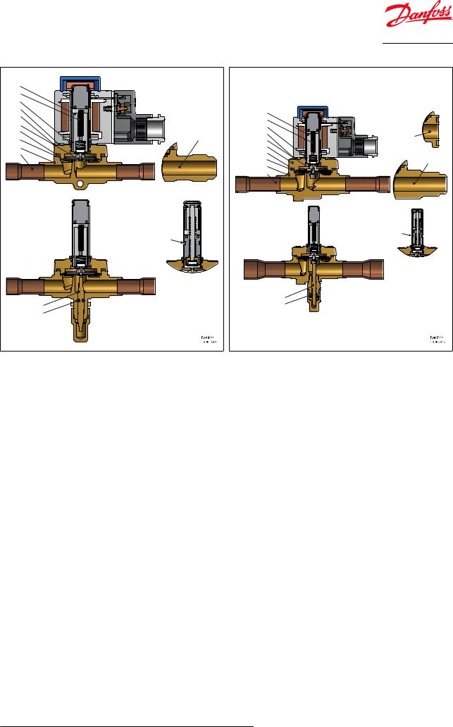
Figure 4: EVR 10 Solder and ‚are connection
3 |
|
6 |
|
9 |
|
8 |
|
2 |
|
4 |
|
7 |
|
5 |
11 |
1 |
|
10 |
|
|
T |
|
12 |
|
13 |
Figure 5: EVR 15 - EVR 18 Solder, ‚are, and ‚ange |
|
|
3 |
|
|
6 |
|
|
9 |
|
|
8 |
14 |
|
4 |
|
|
|
|
|
2 |
|
|
7 |
|
|
5 |
|
11 |
1 |
|
|
|
|
|
10 |
|
|
|
T |
|
|
12 |
|
|
13 |
|
Table 4: Design and material for EVR 10, EVR 15, EVR 18
Pos. no. |
Description |
Material |
1 |
Valve housing assembly |
Brass |
2 |
Cover |
Stainless steel |
3 |
Armature assembly |
Stainless steel/PTFE |
4 |
Diaphragm assembly |
Stainless steel/PTFE |
5 |
Support washer |
Stainless steel |
6 |
Armature spring |
Stainless steel |
7 |
Seal |
Chloroprene rubber |
8 |
Screws |
Stainless steel |
9 |
O-ring |
EPDM rubber |
10 |
Solder connection |
Copper |
11 |
Flare connection |
Brass |
12 |
Manual stem |
Brass |
13 |
O-ring |
Chloroprene rubber |
14 |
Flange connection |
Brass |
T |
Normally Open (NO) tube design |
|
|
|
|
© Danfoss | Climate Solutions | 2021.02 |
AI249086497583en-001301 | 8 |

Solenoid valve, Type EVR 2 - EVR 40
Figure 6: EVR 20 - EVR 22 Solder and ‚ange connection
|
3 |
|
|
6 |
|
|
9 |
|
|
8 |
|
|
2 |
|
|
7 |
|
|
5 |
14 |
4 |
1 |
|
10 |
|
|
|
|
T |
|
12 |
|
|
13 |
|
Figure 7: EVR 25 Solder connection
|
3 |
|
6 |
15 |
9 |
17 |
2 |
8 |
7 |
16 |
1 |
18 |
10 |
|
T |
|
12 |
|
13 |
Table 5: Design and material for EVR 20, EVR 22, EVR 25
Pos. no. |
Description |
Material |
1 |
Valve housing assembly |
Brass |
2 |
Cover |
Stainless steel |
3 |
Armature assembly |
Stainless steel/PTFE |
4 |
Diaphragm assembly |
Stainless steel/PTFE |
5 |
Support washer |
Stainless steel |
6 |
Armature spring |
Stainless steel |
7 |
Seal |
Chloroprene rubber |
8 |
Screws |
Stainless steel |
9 |
O-ring |
EPDM rubber |
10 |
Solder connection |
Copper |
11 |
Flare connection |
Brass |
12 |
Manual stem |
Brass |
13 |
O-ring |
Chloroprene rubber |
14 |
Flange connection |
Brass |
15 |
Gasket |
Aluminum |
16 |
Insert |
Nylon |
17 |
Piston spring |
Stainless steel |
18 |
Piston |
Stainless steel |
T |
Normally Open (NO) tube design |
|
|
|
|
© Danfoss | Climate Solutions | 2021.02 |
AI249086497583en-001301 | 9 |
 Loading...