


LBP 5000
Table of contents
 Loading...
Jan 19 2006
Service Manual
LBP5000 Series
LBP5000


Application
This manual has been issued by Canon Inc. for qualified persons to learn technical theory, installation, maintenance, and repair
of products. This manual covers all localities where the products are sold. For this reason, there may be information in this
manual that does not apply to your locality.
Corrections
This manual may contain technical inaccuracies or typographical errors due to improvements or changes in products. When
changes occur in applicable products or in the contents of this manual, Canon will release technical information as the need
arises. In the event of major changes in the contents of this manual over a long or short period, Canon will issue a new edition
of this manual.
The following paragraph does not apply to any countries where such provisions are inconsistent with local law.
Trademarks
The product names and company names used in this manual are the registered trademarks of the individual companies.
Copyright
This manual is copyrighted with all rights reserved. Under the copyright laws, this manual may not be copied, reproduced or
translated into another language, in whole or in part, without the written consent of Canon Inc.
COPYRIGHT © 2001 CANON INC.
Printed in Japan
Caution
Use of this manual should be strictly supervised to avoid disclosure of confidential information.
Introduction
Symbols Used
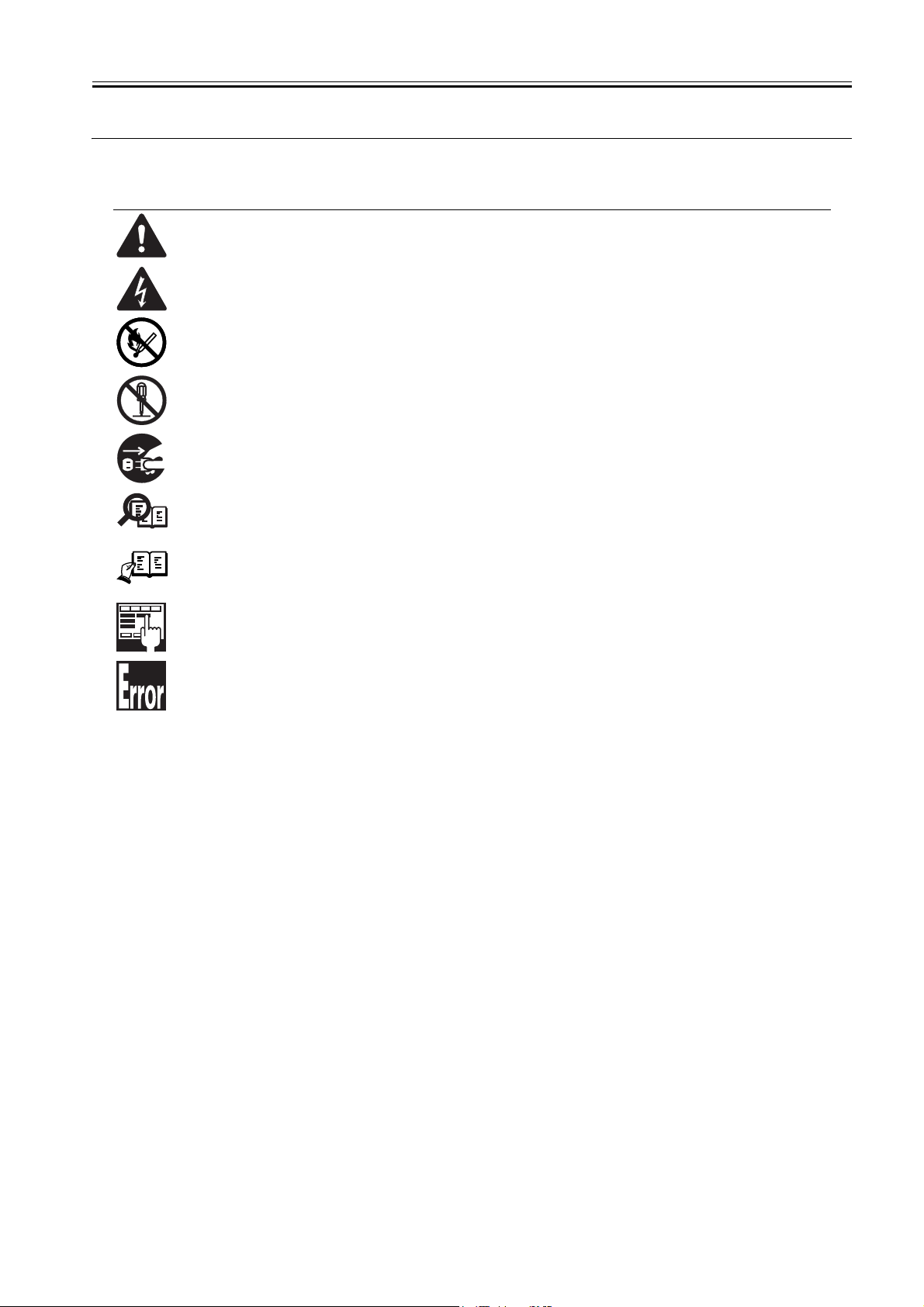
This documentation uses the following symbols to indicate special information:
Symbol Description
Indicates an item of a non-specific nature, possibly classified as Note, Caution, or Warning.
Indicates an item requiring care to avoid electric shocks.
Indicates an item requiring care to avoid combustion (fire).
Indicates an item prohibiting disassembly to avoid electric shocks or problems.
Indicates an item requiring disconnection of the power plug from the electric outlet.
Indicates an item intended to provide notes assisting the understanding of the topic in question.
Indicates an item of reference assisting the understanding of the topic in question.
Provides a description of a service mode.
Provides a description of the nature of an error indication.
Memo
REF.

Introduction
The following rules apply throughout this Service Manual:
1. Each chapter contains sections explaining the purpose of specific functions and the relationship between electrical and mechanical systems with refer-
ence to the timing of operation.
In the diagrams, represents the path of mechanical drive; where a signal name accompanies the symbol , the arrow indicates the
direction of the electric signal.
The expression "turn on the power" means flipping on the power switch, closing the front door, and closing the delivery unit door, which results in
supplying the machine with power.
2. In the digital circuits, '1'is used to indicate that the voltage level of a given signal is "High", while '0' is used to indicate "Low".(The voltage value, how-
ever, differs from circuit to circuit.) In addition, the asterisk (*) as in "DRMD*" indicates that the DRMD signal goes on when '0'.
In practically all cases, the internal mechanisms of a microprocessor cannot be checked in the field. Therefore, the operations of the microprocessors
used in the machines are not discussed: they are explained in terms of from sensors to the input of the DC controller PCB and from the output of the
DC controller PCB to the loads.
The descriptions in this Service Manual are subject to change without notice for product improvement or other purposes, and major changes will be com-
municated in the form of Service Information bulletins.
All service persons are expected to have a good understanding of the contents of this Service Manual and all relevant Service Information bulletins and be
able to identify and isolate faults in the machine."


Contents
Contents
Chapter 1 PRODUCT DESCRIPTION
1.1 Features ..................................................................................................................................................... 1- 1
1.1.1 Feature ....................................................................................................................................................................1- 1
1.2 System construction ................................................................................................................................... 1- 1
1.2.1 System Construction ...............................................................................................................................................1- 1
1.3 Product Specifications ................................................................................................................................1- 1
1.3.1 Product Specifications .............................................................................................................................................1- 1
1.4 Name of Parts.............................................................................................................................................1- 3
1.4.1 External View...........................................................................................................................................................1- 3
1.4.2 Cross Section View .................................................................................................................................................1- 5
1.5 Using the Machine......................................................................................................................................1- 5
1.5.1 Control Panel...........................................................................................................................................................1- 5
1.6 Safety ......................................................................................................................................................... 1- 6
1.6.1 Safety of the Laser Light..........................................................................................................................................1- 6
1.6.2 Regulations Under the Center for Devices and Radiological Health (CDRH) .........................................................1- 6
1.6.3 Handling the Laser Unit ...........................................................................................................................................1- 6
1.6.4 Safety of Toner........................................................................................................................................................1- 6
Chapter 2 TECHNICAL REFERENCE
2.1 Functional Configuration............................................................................................................................. 2- 1
2.1.1 Outline .....................................................................................................................................................................2- 1
2.2 Basic Sequense..........................................................................................................................................2- 1
2.2.1 Basic Sequence of Operation..................................................................................................................................2- 1
2.2.2 Power-On Sequence ...............................................................................................................................................2- 1
2.3 LASER EXPOSURE SYSTEM ...................................................................................................................2- 2
2.3.1 Overview/Configuration ...........................................................................................................................................2- 2
2.3.1.1 Outline...................................................................................................................................................................................... 2- 2
2.3.2 Laser Control ...........................................................................................................................................................2- 4
2.3.2.1 Outline...................................................................................................................................................................................... 2- 4
2.3.2.2 Laser Emission Control ............................................................................................................................................................ 2- 4
2.3.2.3 Automatic power control (APC)................................................................................................................................................ 2- 4
2.3.2.4 Horizontal synchronous control................................................................................................................................................ 2- 5
2.3.2.5 Image Mask Control ................................................................................................................................................................. 2- 5
2.3.2.6 Fault Detection ......................................................................................................................................................................... 2- 5
2.3.3 Laser Scanner Motor Control ..................................................................................................................................2- 5
2.3.3.1 Outline...................................................................................................................................................................................... 2- 5
2.3.3.2 Speed Control .......................................................................................................................................................................... 2- 6
2.3.3.3 Phase Control .......................................................................................................................................................................... 2- 6
2.3.3.4 Fault Detection ......................................................................................................................................................................... 2- 6
2.4 IMAGE FORMATION SYSTEM.................................................................................................................. 2- 7
2.4.1 Overview/Configuration ...........................................................................................................................................2- 7
2.4.1.1 Outline...................................................................................................................................................................................... 2- 7
2.4.1.2 Image Formation Process ........................................................................................................................................................ 2- 7
2.4.1.3 Electrostatic latent image formation block ............................................................................................................................... 2- 8
2.4.1.4 Developing block...................................................................................................................................................................... 2- 9
2.4.1.5 Transfer block ........................................................................................................................................................................ 2- 10
2.4.1.6 Fixing block ............................................................................................................................................................................ 2- 11
2.4.1.7 Drum cleaning block .............................................................................................................................................................. 2- 11
2.4.2 High-Voltage Control .............................................................................................................................................2- 11
2.4.2.1 Outline.................................................................................................................................................................................... 2- 11
2.4.2.2 Generation of the Primary Charging Bias .............................................................................................................................. 2- 12

Contents
2.4.2.3 Generation of the Developing Bias ........................................................................................................................................ 2- 12
2.4.2.4 Generation of the Transfer Bias ............................................................................................................................................. 2- 12
2.4.2.5 Generation of the Fixing Bias................................................................................................................................................. 2- 13
2.4.3 Image Stabilizaton Control.....................................................................................................................................2- 13
2.4.3.1 Overview of the Image Stabilization Control Mechanism....................................................................................................... 2- 13
2.4.3.2 Environment corrective control .............................................................................................................................................. 2- 13
2.4.3.3 Image density corrective control (D-max control) .................................................................................................................. 2- 13
2.4.3.4 Image halftone corrective control (D-half control) .................................................................................................................. 2- 13
2.4.3.5 Image density detection control ............................................................................................................................................. 2- 13
2.4.3.6 Overview of Color Misregistration Corrective Control ........................................................................................................... 2- 14
2.4.3.7 Color misregistration detection .............................................................................................................................................. 2- 14
2.4.4 Toner Cartridge......................................................................................................................................................2- 15
2.4.4.1 Outline.................................................................................................................................................................................... 2- 15
2.4.4.2 Memory Tag Control .............................................................................................................................................................. 2- 16
2.4.4.3 Detection of Toner cartridge presence/absence .................................................................................................................... 2- 16
2.4.4.4 Detecting the End of Life of the Cartridge .............................................................................................................................. 2- 16
2.4.4.5 Detecting the Level of Toner .................................................................................................................................................. 2- 16
2.4.5 Transfer Unit ..........................................................................................................................................................2- 16
2.4.5.1 ETB Unit................................................................................................................................................................................. 2- 16
2.4.5.2 ETB Cleaning ......................................................................................................................................................................... 2- 17
2.5 Pickup/Feeding/Delivery System.............................................................................................................. 2- 18
2.5.1 Overview/Configuration..........................................................................................................................................2- 18
2.5.1.1 Outline.................................................................................................................................................................................... 2- 18
2.5.2 Other Control .........................................................................................................................................................2- 20
2.5.2.1 outline .................................................................................................................................................................................... 2- 20
2.5.2.2 Picking Up Paper from the Cassette ...................................................................................................................................... 2- 21
2.5.2.3 Picking Up Paper from the Manual Feeder ............................................................................................................................ 2- 21
2.5.2.4 Moving the Print Paper .......................................................................................................................................................... 2- 21
2.5.2.5 Transport Speed Control........................................................................................................................................................ 2- 22
2.5.2.6 Paper loop control .................................................................................................................................................................. 2- 22
2.5.2.7 Automatic release of fixing pressure mechanism .................................................................................................................. 2- 23
2.5.3 Detecting Jams ......................................................................................................................................................2- 23
2.5.3.1 Jam Detection Outline............................................................................................................................................................ 2- 23
2.5.3.2 Delay Jams ............................................................................................................................................................................ 2- 24
2.5.3.3 Stationary Jams ..................................................................................................................................................................... 2- 24
2.5.3.4 Other Jams ............................................................................................................................................................................ 2- 24
2.6 FIXING UNIT SYSTEM ............................................................................................................................ 2- 24
2.6.1 Overview/Configuration..........................................................................................................................................2- 24
2.6.1.1 Outline.................................................................................................................................................................................... 2- 24
2.6.2 Various Control Mechanisms.................................................................................................................................2- 25
2.6.2.1 Fixing Temperature Control ................................................................................................................................................... 2- 25
2.6.3 Protective Functions ..............................................................................................................................................2- 27
2.6.3.1 Outline.................................................................................................................................................................................... 2- 27
2.6.3.2 Fault Detection ....................................................................................................................................................................... 2- 27
2.7 EXTERNAL AND CONTROLS SYSTEM ................................................................................................. 2- 27
2.7.1 Power Supply.........................................................................................................................................................2- 27
2.7.1.1 Power Supply ......................................................................................................................................................................... 2- 27
2.7.1.2 Other Function ....................................................................................................................................................................... 2- 28
2.8 ENGINE CONTROL SYSTEM ................................................................................................................. 2- 29
2.8.1 Construction...........................................................................................................................................................2- 29
2.8.1.1 Outline.................................................................................................................................................................................... 2- 29
2.8.2 DC Controller .........................................................................................................................................................2- 29
2.8.2.1 Outline.................................................................................................................................................................................... 2- 29
2.8.2.2 Operation of Individual Blocks ............................................................................................................................................... 2- 30
2.8.2.3 Fan/Motor Control .................................................................................................................................................................. 2- 31
2.8.2.4 Main Motor Fault Detection .................................................................................................................................................... 2- 31
2.8.2.5 Fan Motor Fault Detection ..................................................................................................................................................... 2- 31
2.8.3 Video Controller PCB.............................................................................................................................................2- 31
2.8.3.1 Outline.................................................................................................................................................................................... 2- 31
2.8.3.2 Overview of the Block ............................................................................................................................................................ 2- 32

Contents
Chapter 3 DISASSEMBLY AND ASSEMBLY
3.1 Before Parts Replacement .........................................................................................................................3- 1
3.1.1 Outline .....................................................................................................................................................................3- 1
3.2 EXTERNAL AND CONTROLS SYSTEM ...................................................................................................3- 2
3.2.1 Rear Cover ..............................................................................................................................................................3- 2
3.2.1.1 Removing the Rear Cover ....................................................................................................................................................... 3- 2
3.2.2 Right Cover..............................................................................................................................................................3- 2
3.2.2.1 Removing the Right Cover/Right Cassette Cover.................................................................................................................... 3- 2
3.2.3 Left Cover ................................................................................................................................................................3- 3
3.2.3.1 The former procedure of removing the Left Cover/Left Cassette Cover .................................................................................. 3- 3
3.2.3.2 Removing the Left Cover/Left Cassette Cover ........................................................................................................................ 3- 3
3.2.4 Upper Cover ............................................................................................................................................................ 3- 3
3.2.4.1 The former procedure of removing the Upper Cover .............................................................................................................. 3- 3
3.2.4.2 Removing the Upper Cover ..................................................................................................................................................... 3- 3
3.2.5 Front Cover..............................................................................................................................................................3- 3
3.2.5.1 The former procedure of removing the Front Cover ............................................................................................................... 3- 3
3.2.5.2 Removing the Front Cover ....................................................................................................................................................... 3- 3
3.2.6 Delivery Tray ...........................................................................................................................................................3- 4
3.2.6.1 Removing the Delivery Tray..................................................................................................................................................... 3- 4
3.2.7 Face-down Cover ....................................................................................................................................................3- 4
3.2.7.1 The former procedure of removing the Face-Down Cover ...................................................................................................... 3- 4
3.2.7.2 Removing the Face-Down Cover ............................................................................................................................................. 3- 4
3.2.8 Main Drive Unit ........................................................................................................................................................ 3- 4
3.2.8.1 The former procedure of removing the Main Drive Assembly.................................................................................................. 3- 4
3.2.8.2 Removing the Main Drive Assembly ........................................................................................................................................ 3- 5
3.2.9 Main Motor...............................................................................................................................................................3- 6
3.2.9.1 The former procedure of removing the Main Motor ................................................................................................................. 3- 6
3.2.9.2 Removing the Main Motor ........................................................................................................................................................ 3- 6
3.2.10 DC Controller PCB.................................................................................................................................................3- 7
3.2.10.1 The former procedure of removing the DC Controller PCB ................................................................................................... 3- 7
3.2.10.2 Removing the DC Controller PCB .......................................................................................................................................... 3- 7
3.2.11 Video Controller PCB.............................................................................................................................................3- 7
3.2.11.1 The former procedure of removing the Video Controller PCB ............................................................................................... 3- 7
3.2.11.2 Removing the Video Controller .............................................................................................................................................. 3- 7
3.2.12 Memory Controller PCB.........................................................................................................................................3- 8
3.2.12.1 The former procedure of Removing the Memory Controller PCB .......................................................................................... 3- 8
3.2.12.2 Removing the Memory Controller PCB .................................................................................................................................. 3- 8
3.2.13 Low-Voltage Power Supply Assembly ...................................................................................................................3- 8
3.2.13.1 The former procedure of Removing the Low-Voltage Power Supply PCB............................................................................. 3- 8
3.2.13.2 Removing the Low-Voltage Power Supply PCB .................................................................................................................... 3- 8
3.2.14 High-voltage PCB ..................................................................................................................................................3- 9
3.2.14.1 The former procedure of Removing the High-Voltage Power Supply PCB ............................................................................ 3- 9
3.2.14.2 Removing the High-Voltage Power Supply PCB.................................................................................................................... 3- 9
3.2.15 Machine Outside Environment Sensor ................................................................................................................3- 10
3.2.15.1 The former procedure of removing the Site Environment Sensor ....................................................................................... 3- 10
3.2.15.2 Removing the Site Environment Sensor .............................................................................................................................. 3- 10
3.2.16 Cartridge Fan.......................................................................................................................................................3- 11
3.2.16.1 The former procedure of removing Removing the Cartridge Fan ....................................................................................... 3- 11
3.2.16.2 Removing the Cartridge Fan ................................................................................................................................................ 3- 11
3.3 LASER EXPOSURE SYSTEM .................................................................................................................3- 11
3.3.1 Laser Scanner Unit................................................................................................................................................3- 11
3.3.1.1 The former procedure of removing the Laser Scanner Unit.................................................................................................. 3- 11
3.3.1.2 Removing the Laser Scanner Unit ......................................................................................................................................... 3- 11
3.4 IMAGE FORMATION SYSTEM................................................................................................................ 3- 12
3.4.1 MCY Developing Cylinder Drive Solenoid .............................................................................................................3- 12
3.4.1.1 The former procedure of removing the MCY Developing Cylinder Drive Solenoid ............................................................... 3- 12
3.4.1.2 Removing the MCY Developing Cylinder Drive Solenoid ...................................................................................................... 3- 12
3.4.2 Bk Developing Cylinder Drive Solenoid.................................................................................................................3- 12

Contents
3.4.2.1 The former procedure of removing the Bk Developing Cylinder Drive Solenoid................................................................... 3- 12
3.4.2.2 Removing the Bk Developing Cylinder Drive Solenoid .......................................................................................................... 3- 12
3.4.3 ETB Unit.................................................................................................................................................................3- 12
3.4.3.1 The former procedure of removing the ETB Unit .................................................................................................................. 3- 12
3.4.3.2 Removing the ETB Unit ......................................................................................................................................................... 3- 13
3.5 PICKUP/FEEDING/DELIVERY SYSTEM................................................................................................. 3- 13
3.5.1 Paper Pick-up Feeder Unit.....................................................................................................................................3- 13
3.5.1.1 The former procedure of removing the Pickup/Transport Assembly..................................................................................... 3- 13
3.5.1.2 Removing the Pickup/Transport Assembly ............................................................................................................................ 3- 13
3.5.2 Pickup Motor..........................................................................................................................................................3- 14
3.5.2.1 The former procedure of removing the Pickup Motor ........................................................................................................... 3- 14
3.5.2.2 Removing the Pickup Motor .................................................................................................................................................. 3- 14
3.5.3 Cassette Pickup Roller...........................................................................................................................................3- 15
3.5.3.1 Removing the Pickup Roller................................................................................................................................................... 3- 15
3.5.4 Cassette Pick-up Solenoid.....................................................................................................................................3- 15
3.5.4.1 The former procedure of removing the Cassette Pickup Solenoid ........................................................................................ 3- 15
3.5.4.2 Removing the Cassette Pickup Solenoid ............................................................................................................................... 3- 15
3.5.5 Cassette Separation Pad.......................................................................................................................................3- 15
3.5.5.1 Removing the Separation Pad ............................................................................................................................................... 3- 15
3.5.6 Manual Paper Sensor ............................................................................................................................................3- 15
3.5.6.1 The former procedure of removing the Manual Feeder Paper Sensor .................................................................................. 3- 15
3.5.6.2 Removing the Manual Feeder Paper Sensor......................................................................................................................... 3- 15
3.5.7 Registration Before Sensor....................................................................................................................................3- 16
3.5.7.1 The former procedure of removing the Registration Sensor .................................................................................................. 3- 16
3.5.7.2 Removing the Registration Sensor ........................................................................................................................................ 3- 16
3.6 FIXING SYSTEM...................................................................................................................................... 3- 16
3.6.1 Fixing Assembly.....................................................................................................................................................3- 16
3.6.1.1 The former procedure of removing the Fixing Assembly ....................................................................................................... 3- 16
3.6.1.2 Removing the Fixing Assembly.............................................................................................................................................. 3- 16
3.6.2 Fixing Film Unit ......................................................................................................................................................3- 17
3.6.2.1 The former procedure of removing the Fixing Film ................................................................................................................ 3- 17
3.6.2.2 Removing the Fixing Film ...................................................................................................................................................... 3- 17
3.6.3 Fixing Pressure Roller............................................................................................................................................3- 19
3.6.3.1 The former procedure of removing the Fixing Pressure Roller .............................................................................................. 3- 19
3.6.3.2 Removing the Fixing Pressure Roller .................................................................................................................................... 3- 19
3.6.4 Fixing Motor ...........................................................................................................................................................3- 19
3.6.4.1 The former procedure of removing the Fixing/Delivery Motor................................................................................................ 3- 19
3.6.4.2 Removing the Fixing/Delivery Motor ...................................................................................................................................... 3- 19
Chapter 4 MAINTENANCE AND INSPECTION
4.1 Periodically Replaced Parts ....................................................................................................................... 4- 1
4.1.1 Periodically Replaced Parts.....................................................................................................................................4- 1
4.2 Consumables ............................................................................................................................................. 4- 1
4.2.1 Durables Replaced by the User...............................................................................................................................4- 1
4.2.2 Durables Replaced by the Service Person ..............................................................................................................4- 1
4.3 Periodical Service....................................................................................................................................... 4- 1
4.3.1 Periodic Service.......................................................................................................................................................4- 1
4.4 Cleaning ..................................................................................................................................................... 4- 1
4.4.1 Pickup Roller............................................................................................................................................................4- 1
4.4.2 Separation Pad ........................................................................................................................................................4- 1
4.4.3 Registration Roller ...................................................................................................................................................4- 1
4.4.4 Registration Sub Roller............................................................................................................................................4- 1
4.4.5 Registration Shutter .................................................................................................................................................4- 1
4.4.6 Transport Guide.......................................................................................................................................................4- 1
4.4.7 Delivery Roller..........................................................................................................................................................4- 1
4.4.8 Fixing Inlet Guide.....................................................................................................................................................4- 1
4.4.9 Fixing Pressure Roller..............................................................................................................................................4- 1

Contents
4.5 User Maintenance ......................................................................................................................................4- 2
4.5.1 Outline .....................................................................................................................................................................4- 2
4.5.2 List Of Special Print Mode.......................................................................................................................................4- 3
Chapter 5 TROUBLESHOOTING
5.1 Countermeasures .......................................................................................................................................5- 1
5.1.1 Image Faults............................................................................................................................................................5- 1
5.1.1.1 Out of Focus ............................................................................................................................................................................ 5- 1
5.2 MEASUREMENT AND ADJUSTMENT ......................................................................................................5- 1
5.2.1 Test Print .................................................................................................................................................................5- 1
5.2.1.1 Test Print.................................................................................................................................................................................. 5- 1
5.2.2 Adjustment of Fixing System ..................................................................................................................................5- 2
5.2.2.1 Checking the Nip Width (fixing pressure roller)........................................................................................................................ 5- 2
5.3 SERVICE TOOLS.......................................................................................................................................5- 2
5.3.1 Standard Tools ........................................................................................................................................................5- 2
5.3.2 Solvent/Oil List.........................................................................................................................................................5- 3
5.4 Location of Convectors ............................................................................................................................... 5- 3
5.4.1 Connectors ..............................................................................................................................................................5- 3
5.5 ERROR CODE ........................................................................................................................................... 5- 5
5.5.1 Error Code ...............................................................................................................................................................5- 5
5.6 Sevice Mode...............................................................................................................................................5- 7
5.6.1 Outline .....................................................................................................................................................................5- 7
5.6.1.1 Outline...................................................................................................................................................................................... 5- 7
5.6.2 Service Mode Table.................................................................................................................................................5- 7
5.6.2.1 Service Mode Items ................................................................................................................................................................. 5- 7
Chapter 6 APPENDIX
6.1 OUTLINE OF ELECTRICAL COMPONENTS ............................................................................................ 6- 1
6.1.1 Clutch/Solenoid .......................................................................................................................................................6- 1
6.1.1.1 Solenoids ................................................................................................................................................................................. 6- 1
6.1.2 Motor/Fan ................................................................................................................................................................6- 2
6.1.2.1 Motors and Fans ...................................................................................................................................................................... 6- 2
6.1.3 Sensor .....................................................................................................................................................................6- 3
6.1.3.1 Sensors.................................................................................................................................................................................... 6- 3
6.1.4 PCBs .......................................................................................................................................................................6- 4
6.1.4.1 PCBs........................................................................................................................................................................................ 6- 4

Contents

Chapter 1 PRODUCT DESCRIPTION


Contents
Contents
1.1 Features ..........................................................................................................................................................................1-1
1.1.1 Feature.......................................................................................................................................................................................... 1-1
1.2 System construction .......................................................................................................................................................1-1
1.2.1 System Construction .................................................................................................................................................................... 1-1
1.3 Product Specifications....................................................................................................................................................1-1
1.3.1 Product Specifications ................................................................................................................................................................. 1-1
1.4 Name of Parts.................................................................................................................................................................1-3
1.4.1 External View .............................................................................................................................................................................. 1-3
1.4.2 Cross Section View...................................................................................................................................................................... 1-5
1.5 Using the Machine .........................................................................................................................................................1-5
1.5.1 Control Panel ............................................................................................................................................................................... 1-5
1.6 Safety .............................................................................................................................................................................1-6
1.6.1 Safety of the Laser Light.............................................................................................................................................................. 1-6
1.6.2 Regulations Under the Center for Devices and Radiological Health (CDRH)............................................................................ 1-6
1.6.3 Handling the Laser Unit............................................................................................................................................................... 1-6
1.6.4 Safety of Toner ............................................................................................................................................................................ 1-6

Chapter 1
1-1
1.1 Features
1.1.1 Feature
0010-5849
1. Smallest Color LBP
The machine has the smallest body of all Canon color LBPs.
2. Electrostatic Transportation Belt (ETB)
The machine uses an ETB for movement of media and transfer of images. The direct transfer of color images from the photosensitive drum to media has enable
a significant increase in printing speed.
3. Four consecutive drum method (Inline method)
The machine uses a 4-drum construction, in which 4 toner cartridges are arranged in a straight line for one-shot transfer of 4 colors. Compared with the
conventional rotary construction, it brings about a bigger reduction in transfer time and a bigger increase in printing speed (full color).
4. Integrated Laser Scanner Unit
The machine uses a 4-beam/2-mirror mechanism in which 2 laser beams (colors) are directed to each polygon mirror. Thanks to the elimination of the need for
separate laser scanner units commonly found in a 4-drum construction, the machine is less subject to color displacement and has a smaller laser unit.
5. On-Demand Fixing
The machine uses an on-demand fixing method combined with a ceramic heater so far mostly used in a mono-color printer. The fact has led to a shorter warm-
up period and lower energy consumption.
6. Support of Various Media Types
The machine permits the use of transparencies (mono-color prints only), label sheets, envelopes, and postcard-size sheets through both its cassette and manual
feeder.
Moreover, it also permits the use of heavy paper (163 g/m2 max.) in its cassette.
7. High-Performance Printing System (CAPT)
The machine draws on the latest developments in CAPT (Canon Advanced Printing Technology), which promises high performance in a Windows operating
system. Thanks to the technology, data processing usually assigned to the printer is now fully undertaken by a PC to take full advantage of the use of a PC for
higher printing speed. Its added benefits include the ability to process a large volume of data without adding memory to the printer.
8. Ease of Maintenance
The toner cartridges (cyan, magenta, yellow, black) each consist of a toner casing and a drum constructed as a single entity. This way, there is no need for toner
replenishment or drum replacement, which could well soil the hands of the user or take up his/her time. Mere replacement of the appropriate toner cartridge is
enough to keep the machine in good working condition.
The access cover is found at the front of the machine so that both cartridge replacement and jam removal are easy. In terms of printing processes, all (pickup,
development, transfer, fixing) take place at the front of the machine, resulting in a highly simple paper path.
1.2 System construction
1.2.1 System Construction
0010-9607
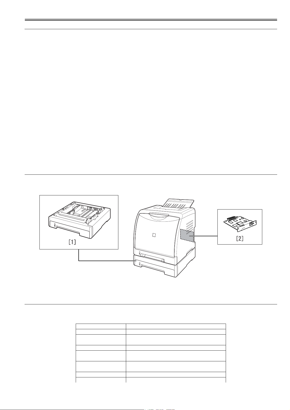
The following shows the machine's system construction:
F-1-1
[1] Paper Feeder PF-92
[2] Network Board NB-C1
1.3 Product Specifications
1.3.1 Product Specifications
0010-6376
Body installation method Desktop page printer
Photosensitive medium OPC drum
Charging method Roller charging
Exposure method Laser scanning
Development method Toner projection development
Transfer method By Electrostatic Transportation Belt
Separation method Curvature
Pickup method By cassette/manual feeder
ER
R
LN
K
100
N
B
-C
1

Chapter 1
1-2
Cassette pickup method By separation pad
Drum cleaning method By blade
Trasnsfer cleaning method Drum static collection
Fixing method On-demand
Delivery method Face-down
Contrast adjustment function Auto
Toner level detection function Available
Toner type non-magnetic, 1-component dry toner
Toner supply type By EP cartridge (for A4/LTR, about 2500 impressions of Bk; about 2000
impressions of M, C, and Y)
Warm-up time 195 sec or less (approx.; at power-on, at 20 deg C)
Image margin (Leading edge) 5.0+1.5/-1.5mm
Image margin (Trailing edge) 5.0+1.5/-1.5mm
Image margin (Left/right) 5.0+1.0/-1.0mm
Number of gradations 16 gradations
Printing resolution 600dpi×600dpi
First print time 20 sec or less (approx.; both mono- and full-color)
Print speed (A4) 8 impressions/min (approx.; both mono- and full color)
Cassette paper size A4, B5, LGL, LTR, Executive, Index Card, envelope, user-defined sheet
(762 to 215.9 mm in length, 127.0 to 355.6 mm in width)
Multifeeder paper size Same as for cassette
Cassette paper type Plain paper (60 to 90 g/m2), heavy paper (91 to 163 g/m2), envelope
(Envelope DL, Envelope COM10, Envelope C5, Envelope
Monarch, Envelope B5), label sheet, transparency ((Black and white
printing only)
Multifeeder tray paper type Same as for cassette
Cassette capacity 250 sheets (64 g/m2)
Multifeeder tray capacity 1 sheet
Delivery tray stack 125 sheets (plain paper, 64 g/m2)
Memory 8 MB (addition not possible)
Auto gradation correction Available
Operating environment
(Temperature range)
10Å` 30Åé
Operating environment
(Humidity range)
10 Å` 80%RH
Operating environment
(Atmospheric pressure)
l810.6 to 1013.3 hpa (0.8 to 1.0 atm)
Noise 25 dB or less (standby); 50 dB or less (print)
Power supply rating 110 - 127 V (±10 %) 50/60 Hz (±2 Hz)
220 - 240 V (±10 %) 50/60 Hz (±2 Hz)
Power consumption (Maximum) ñÒ638W or less (approx.)
Power consumption 18W or less (approx., operating; reference only); 220W or less (approx.,
operating; reference only)
Dimensions 407mm(W) x 367mm(D) x 376mm(H)
Weight 15.7 kg (approx.; excluding cartridges)
Chapter 1
1-3
1.4 Name of Parts
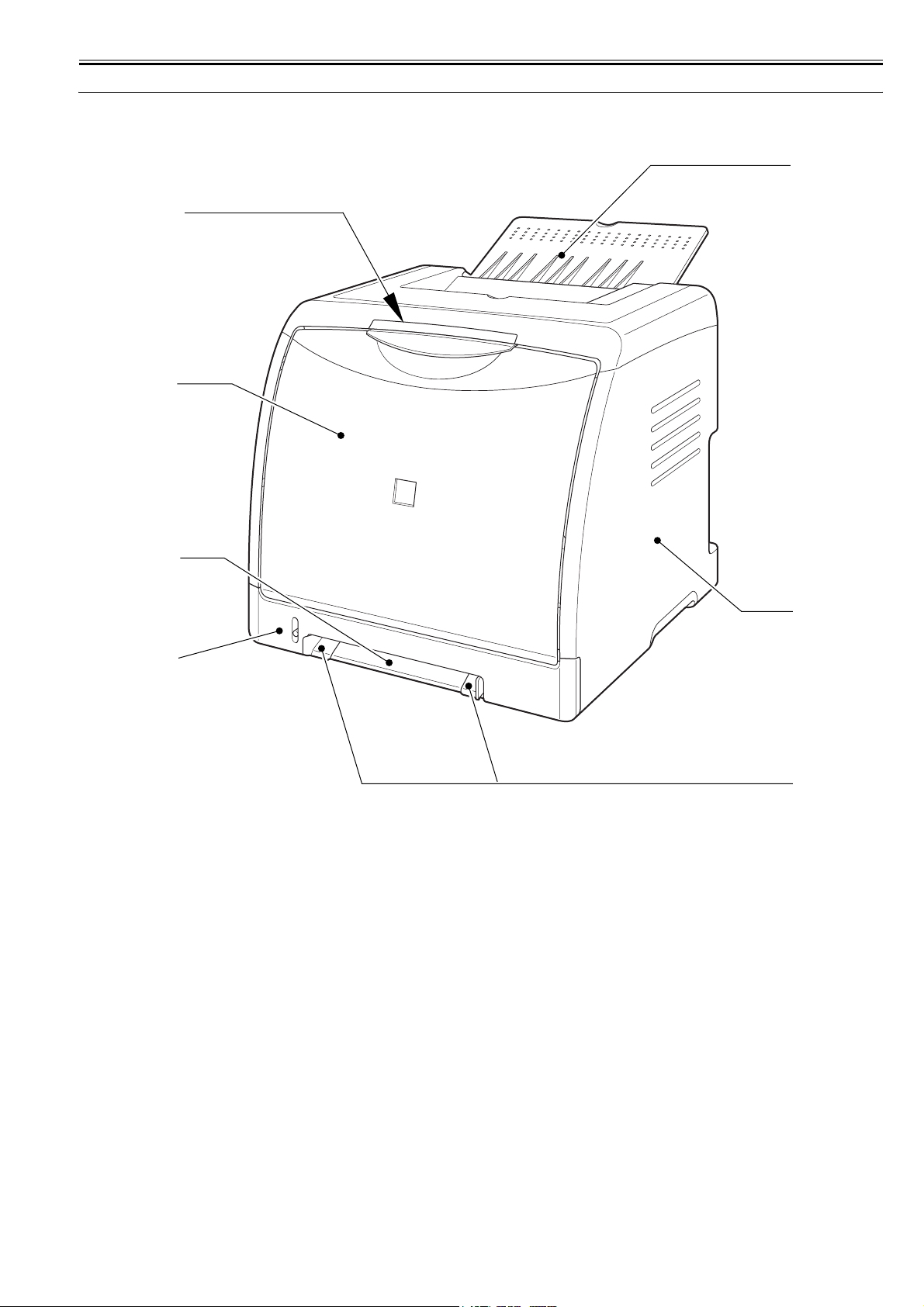
1.4.1 External View
0010-7392
F-1-2
[1] Delivery tray [2] Right cover
[3] Paper guide [4] Cassette
[5] Manual feeder slot [6] Front cover
[7] Lamp unit
[1]
[2]
[3]
[4]
[6]
[5]
[7]
Chapter 1
1-4
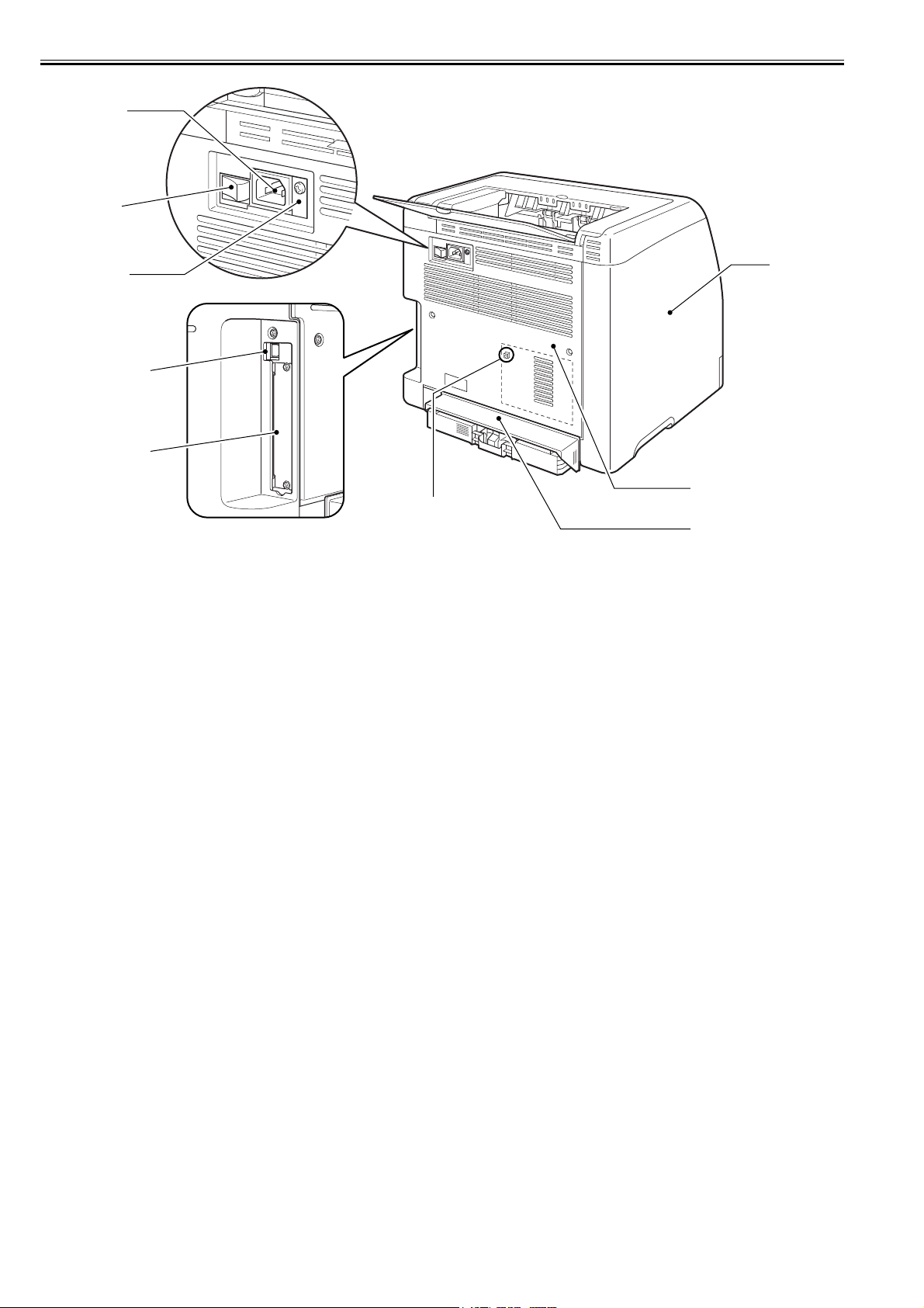
F-1-3
[1] Left cover [2] Rear cover
[3] Cassette protective cover [4] Expansion board slot
[5] USB port [6] Grounding wire terminal
[7] Power supply switch [8] Power supply receptacle
[9] Test Print Switch
(On the DC controller PCB)
[6]
[8]
[1]
[2]
[3]
[7]
[5]
[4]
[9]
Chapter 1
1-5
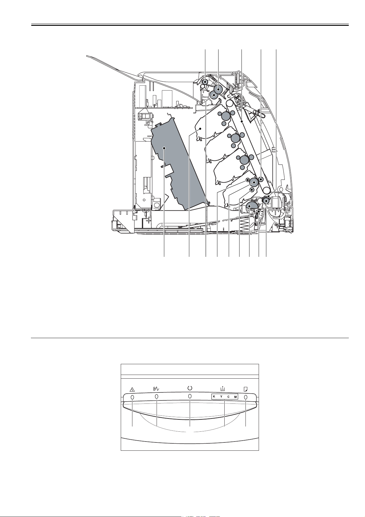
1.4.2 Cross Section View
0010-7393
F-1-4
1.5 Using the Machine
1.5.1 Control Panel
0010-7869
The lamp unit used to indicate the state of the printer consists of multiple LEDs that go on or flash as follows:
F-1-5
[1] Delivery roller [2] Fixing pressure roller
[3] ETB [4] Transfer roller
[5] Registration shutter [6] Registration roller
[7] Separation pad [8] Pickup roller
[9] Developing cylinder [10] Photosensitive roller
[11] Primary charging roller [12] Fixing film unit
[13] Toner cartridge [14] Laser/scanner block
[1] [2] [3] [4] [5]
[6][7][8][9]
[10][11][12][13][14]
[1]
[2] [3] [4] [5]
Chapter 1
1-6
T-1-1
1.6 Safety
1.6.1 Safety of the Laser Light
0010-5913
Laser light can prove to be hazardous to the human body. The machine's laser unit is fully enclosed in a protective housing and external covers so that its light will
not escape outside as long as the machine is used normally.
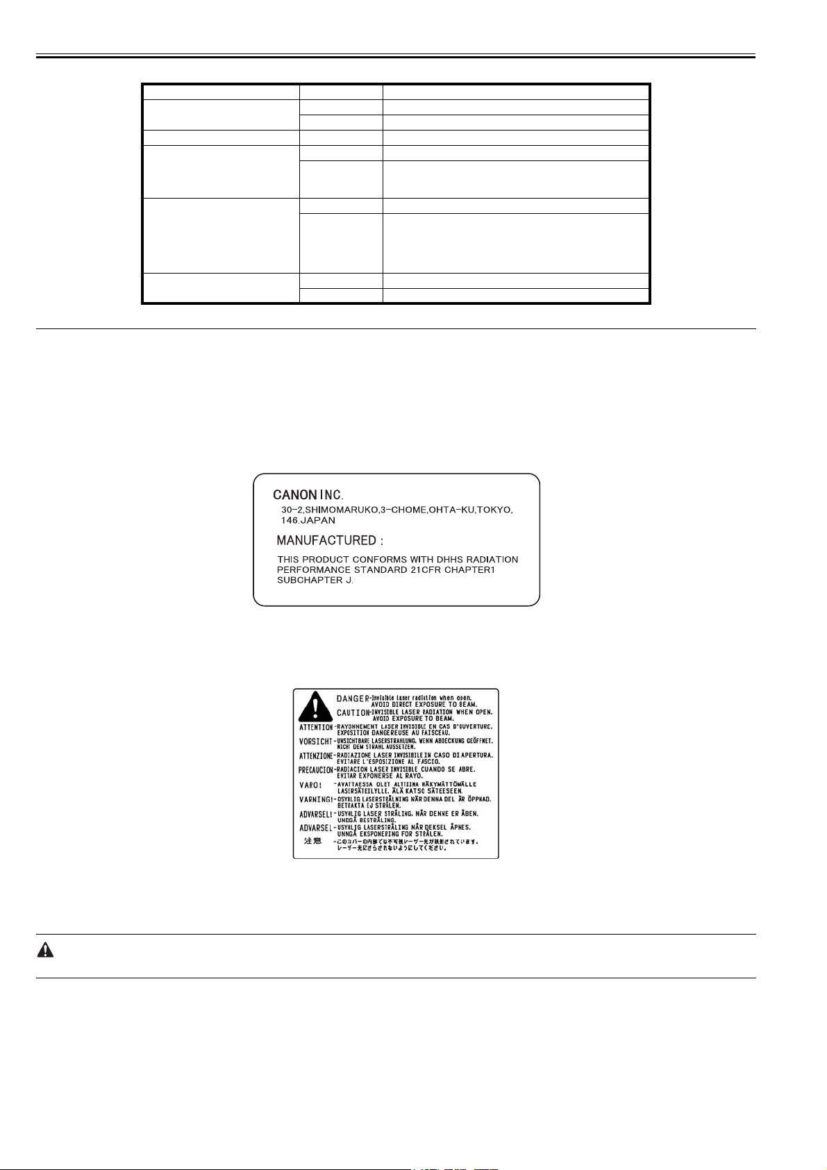
1.6.2 Regulations Under the Center for Devices and Radiological Health (CDRH)
0010-5915
The CDRH of the US Food and Drug Administration put into effect regulations governing the sale of laser products in the US on August 2, 1976. These regulations
apply to all laser products produced on and after August 1, 1976, and a laser product cannot be sold unless it has been certified to comply with the regulations. The
following is the label used to indicate that the product has been certified under the regulations, and all laser products sold in the US must bear the label.
F-1-6
1.6.3 Handling the Laser Unit
0010-5916
The laser/scanner unit emits invisible laser beam. DO NOT disassemble the unit as the laser beam can possibly damage your eyes. The unit cannot be adjusted in
the field. The following label is attached to the cover of the unit:
F-1-7
1.6.4 Safety of Toner
0010-5919
The machine's toner is a non-toxic material composed of plastic, iron, and small amounts of dye.
Do not put the toner into fire. It may explode.
Toner on the Skin or Clothes
1. If your skin or clothes came into contact with toner, use dry tissue to remove the toner, and then wash with water.
2. Do not use warm or hot water, which will cause the toner to jell, permanently fusing it with the fibers of the clothes.
3. Do not bring toner into contact with vinyl material. They are likely to react with each other.
LED On/Flash Description
Alarm Indicator [1]
on Service call is occurring.
flash An error is occurring, disabling printing.
Paper Jam Indicator [2] flash A paper jam is occurring, disabling printing.
Ready Indicator [3]
on The printer is in the sleep mode and ready to print.
flash
engine in operation, printing The printer is busy performing some
kind of processing or operation, such as printing, warming up,
calibrating, or pausing a job.
Toner Indicator [4]
on Toner cartridge replacement is required.
flash
Cannot print because toner cartridge replacement is required or any
toner cartridge is not installed properly.
Indicator of the color that requires toner cartridge replacement
comes on or blinks. "K", "Y", "C", and "M" indicate black, yellow,
cyan, and magenta respectively.
Load Paper Indicator [5]
on There is no paper in any paper source.
flash No paper or paper of an inappropriate size is loaded.

Chapter 2 TECHNICAL REFERENCE


Contents
Contents
2.1 Functional Configuration ...............................................................................................................................................2-1
2.1.1 Outline.......................................................................................................................................................................................... 2-1
2.2 Basic Sequense...............................................................................................................................................................2-1
2.2.1 Basic Sequence of Operation ....................................................................................................................................................... 2-1
2.2.2 Power-On Sequence..................................................................................................................................................................... 2-1
2.3 LASER EXPOSURE SYSTEM.....................................................................................................................................2-2
2.3.1 Overview/Configuration .............................................................................................................................................................. 2-2
2.3.1.1 Outline.............................................................................................................................................................................................................2-2
2.3.2 Laser Control ............................................................................................................................................................................... 2-4
2.3.2.1 Outline.............................................................................................................................................................................................................2-4
2.3.2.2 Laser Emission Control...................................................................................................................................................................................2-4
2.3.2.3 Automatic power control (APC) .....................................................................................................................................................................2-4
2.3.2.4 Horizontal synchronous control ......................................................................................................................................................................2-5
2.3.2.5 Image Mask Control........................................................................................................................................................................................2-5
2.3.2.6 Fault Detection ................................................................................................................................................................................................2-5
2.3.3 Laser Scanner Motor Control....................................................................................................................................................... 2-5
2.3.3.1 Outline.............................................................................................................................................................................................................2-5
2.3.3.2 Speed Control..................................................................................................................................................................................................2-6
2.3.3.3 Phase Control ..................................................................................................................................................................................................2-6
2.3.3.4 Fault Detection ................................................................................................................................................................................................2-6
2.4 IMAGE FORMATION SYSTEM.................................................................................................................................2-7
2.4.1 Overview/Configuration .............................................................................................................................................................. 2-7
2.4.1.1 Outline.............................................................................................................................................................................................................2-7
2.4.1.2 Image Formation Process ................................................................................................................................................................................2-7
2.4.1.3 Electrostatic latent image formation block .....................................................................................................................................................2-8
2.4.1.4 Developing block ............................................................................................................................................................................................2-9
2.4.1.5 Transfer block ...............................................................................................................................................................................................2-10
2.4.1.6 Fixing block ..................................................................................................................................................................................................2-11
2.4.1.7 Drum cleaning block .....................................................................................................................................................................................2-11
2.4.2 High-Voltage Control ................................................................................................................................................................ 2-11
2.4.2.1 Outline...........................................................................................................................................................................................................2-11
2.4.2.2 Generation of the Primary Charging Bias.....................................................................................................................................................2-12
2.4.2.3 Generation of the Developing Bias ...............................................................................................................................................................2-12
2.4.2.4 Generation of the Transfer Bias ....................................................................................................................................................................2-12
2.4.2.5 Generation of the Fixing Bias .......................................................................................................................................................................2-13
2.4.3 Image Stabilizaton Control ........................................................................................................................................................ 2-13
2.4.3.1 Overview of the Image Stabilization Control Mechanism............................................................................................................................2-13
2.4.3.2 Environment corrective control.....................................................................................................................................................................2-13
2.4.3.3 Image density corrective control (D-max control)........................................................................................................................................2-13
2.4.3.4 Image halftone corrective control (D-half control).......................................................................................................................................2-13
2.4.3.5 Image density detection control ....................................................................................................................................................................2-13
2.4.3.6 Overview of Color Misregistration Corrective Control ...............................................................................................................................2-14
2.4.3.7 Color misregistration detection .....................................................................................................................................................................2-14
2.4.4 Toner Cartridge.......................................................................................................................................................................... 2-15
2.4.4.1 Outline...........................................................................................................................................................................................................2-15
2.4.4.2 Memory Tag Control.....................................................................................................................................................................................2-16
2.4.4.3 Detection of Toner cartridge presence/absence ............................................................................................................................................2-16
2.4.4.4 Detecting the End of Life of the Cartridge....................................................................................................................................................2-16
2.4.4.5 Detecting the Level of Toner ........................................................................................................................................................................2-16
2.4.5 Transfer Unit .............................................................................................................................................................................. 2-16
2.4.5.1 ETB Unit .......................................................................................................................................................................................................2-16
2.4.5.2 ETB Cleaning................................................................................................................................................................................................2-17
2.5 Pickup/Feeding/Delivery System.................................................................................................................................2-18

Contents
2.5.1 Overview/Configuration ............................................................................................................................................................ 2-18
2.5.1.1 Outline .......................................................................................................................................................................................................... 2-18
2.5.2 Other Control ............................................................................................................................................................................. 2-20
2.5.2.1 outline ........................................................................................................................................................................................................... 2-20
2.5.2.2 Picking Up Paper from the Cassette ............................................................................................................................................................. 2-21
2.5.2.3 Picking Up Paper from the Manual Feeder .................................................................................................................................................. 2-21
2.5.2.4 Moving the Print Paper ................................................................................................................................................................................. 2-21
2.5.2.5 Transport Speed Control ............................................................................................................................................................................... 2-22
2.5.2.6 Paper loop control ......................................................................................................................................................................................... 2-22
2.5.2.7 Automatic release of fixing pressure mechanism ......................................................................................................................................... 2-23
2.5.3 Detecting Jams ........................................................................................................................................................................... 2-23
2.5.3.1 Jam Detection Outline ..................................................................................................................................................................................2-23
2.5.3.1.1 Outline .................................................................................................................................................................................................. 2-23
2.5.3.2 Delay Jams .................................................................................................................................................................................................... 2-24
2.5.3.2.1 Pick-up delay jam ................................................................................................................................................................................. 2-24
2.5.3.2.2 Delivery delay jam ................................................................................................................................................................................ 2-24
2.5.3.3 Stationary Jams ............................................................................................................................................................................................. 2-24
2.5.3.3.1 Pickup Stationary Jam .......................................................................................................................................................................... 2-24
2.5.3.3.2 Delivery Stationary Jam........................................................................................................................................................................ 2-24
2.5.3.4 Other Jams .................................................................................................................................................................................................... 2-24
2.5.3.4.1 Wrap Jam .............................................................................................................................................................................................. 2-24
2.5.3.4.2 Start-Up Residual Paper Jam ................................................................................................................................................................ 2-24
2.5.3.4.3 Door Open Jam ..................................................................................................................................................................................... 2-24
2.6 FIXING UNIT SYSTEM ............................................................................................................................................ 2-24
2.6.1 Overview/Configuration ............................................................................................................................................................ 2-24
2.6.1.1 Outline .......................................................................................................................................................................................................... 2-24
2.6.2 Various Control Mechanisms .................................................................................................................................................... 2-25
2.6.2.1 Fixing Temperature Control ......................................................................................................................................................................... 2-25
2.6.2.1.1 Fixing Temperature Control ................................................................................................................................................................. 2-25
2.6.3 Protective Functions................................................................................................................................................................... 2-27
2.6.3.1 Outline .......................................................................................................................................................................................................... 2-27
2.6.3.2 Fault Detection.............................................................................................................................................................................................. 2-27
2.7 EXTERNAL AND CONTROLS SYSTEM ............................................................................................................... 2-27
2.7.1 Power Supply ............................................................................................................................................................................. 2-27
2.7.1.1 Power Supply ................................................................................................................................................................................................ 2-27
2.7.1.1.1 Low-Voltage Power Supply PCB ......................................................................................................................................................... 2-27
2.7.1.2 Other Function ..............................................................................................................................................................................................2-28
2.7.1.2.1 Protective Functions ............................................................................................................................................................................. 2-28
2.7.1.2.2 Sleep function ....................................................................................................................................................................................... 2-29
2.7.1.2.3 Connection Power Supply Detection.................................................................................................................................................... 2-29
2.8 ENGINE CONTROL SYSTEM ................................................................................................................................. 2-29
2.8.1 Construction............................................................................................................................................................................... 2-29
2.8.1.1 Outline .......................................................................................................................................................................................................... 2-29
2.8.2 DC Controller............................................................................................................................................................................. 2-29
2.8.2.1 Outline .......................................................................................................................................................................................................... 2-29
2.8.2.2 Operation of Individual Blocks..................................................................................................................................................................... 2-30
2.8.2.3 Fan/Motor Control ........................................................................................................................................................................................ 2-31
2.8.2.4 Main Motor Fault Detection ......................................................................................................................................................................... 2-31
2.8.2.5 Fan Motor Fault Detection............................................................................................................................................................................ 2-31
2.8.3 Video Controller PCB................................................................................................................................................................ 2-31
2.8.3.1 Outline .......................................................................................................................................................................................................... 2-31
2.8.3.2 Overview of the Block .................................................................................................................................................................................. 2-32
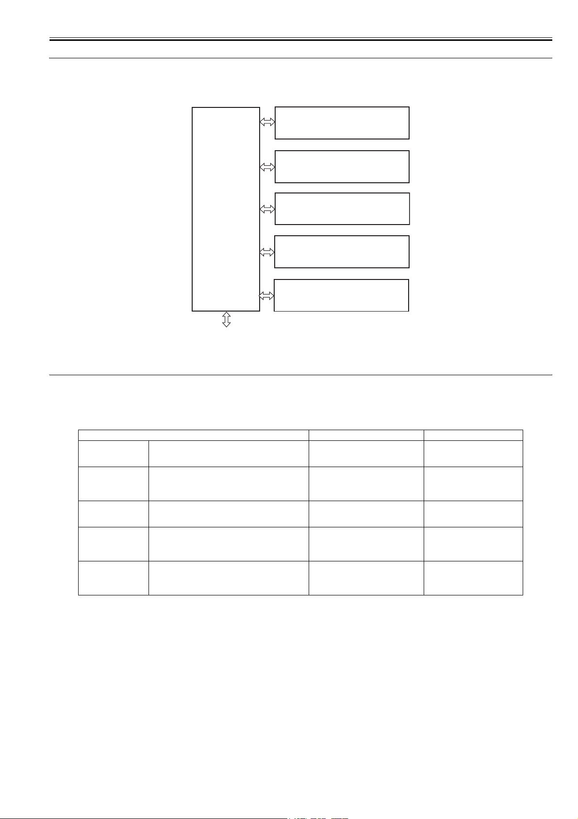
Chapter 2
2-1
2.1 Functional Configuration
2.1.1 Outline
0010-6039
The machine may be broadly divided into the following 6 functional blocks: engine control system, laser exposure system, image formation system, pickup/trans-
port/delivery system, fixing system, and externals/auxiliary control system.
F-2-1
2.2 Basic Sequense
2.2.1 Basic Sequence of Operation
0010-5933
The machine's sequence of operation is controlled by the CPU on its DC controller PCB. The following describes the machine's operation in respect of various
intervals, from when the machine goes on until its main motor stops at the end of a print job:
T-2-1
2.2.2 Power-On Sequence
0010-6042
In power-on sequence, the machine resets itself to make sure that it is free of jams and faults. The machine goes through the following from when the power is
turned on until it enters a standby state:
1) The power is turned on.
2) The CPU is initialized.
3) The ASIC is initialized.
4) The video interface communication is started.
5) Residual paper check by each sensor signaling paper presence.
6) Initial drive for main motor, pick-up motor, and fixing/delivery motor
7) Fixing heater initial drive by controlling fixing temperature targeting for 100 deg C.
8) Initial drive for scanner motor
9) Failure/Abnormality check
Detect scanner failure, fixing unit failure, and door open during the above periods.
10) Communication with memory tag
11) Cartridge presence detection
Interval Description Remarks
WAIT
(wait)
From when the power is turned on until the initial drive of
the main motor stops.
To eliminate the drum surface potential,
and to clean the ETB.
The machine checks the presence/
absence of cartridges during the
interval.
STBY
(standby)
From when the wait period ends, or when last rotation
ends, to when the video controller sends the print
command; or, from when last rotation ends to when the
power is turned off.
To make the machine ready for printing.
INTR
(initial rotation)
From when the video controller sends the print command
to when the pickup solenoid goes on.
To stabilize the sensitivity of the
photosensitive drum in preparation for a
print job.
PRINT
(print)
From when initial rotation ends to when the developing
high voltage goes off.
Forms a toner image on the
photosensitive drum and transfers the
image to print paper according to the
video signal from the video controller.
LSTR
(last rotation)
From when developing high voltage goes on to when the
main motor stops.
To completely discharge the last print
sheet. Also, to clean the ETB.
The machine starts initial rotation
immediately in response to the
print command for the video
controller.
To external device
Engine control
system
Laser exposure system
Pickup/transport/delivery system
Image formation system
Fixing system
Externals and control system
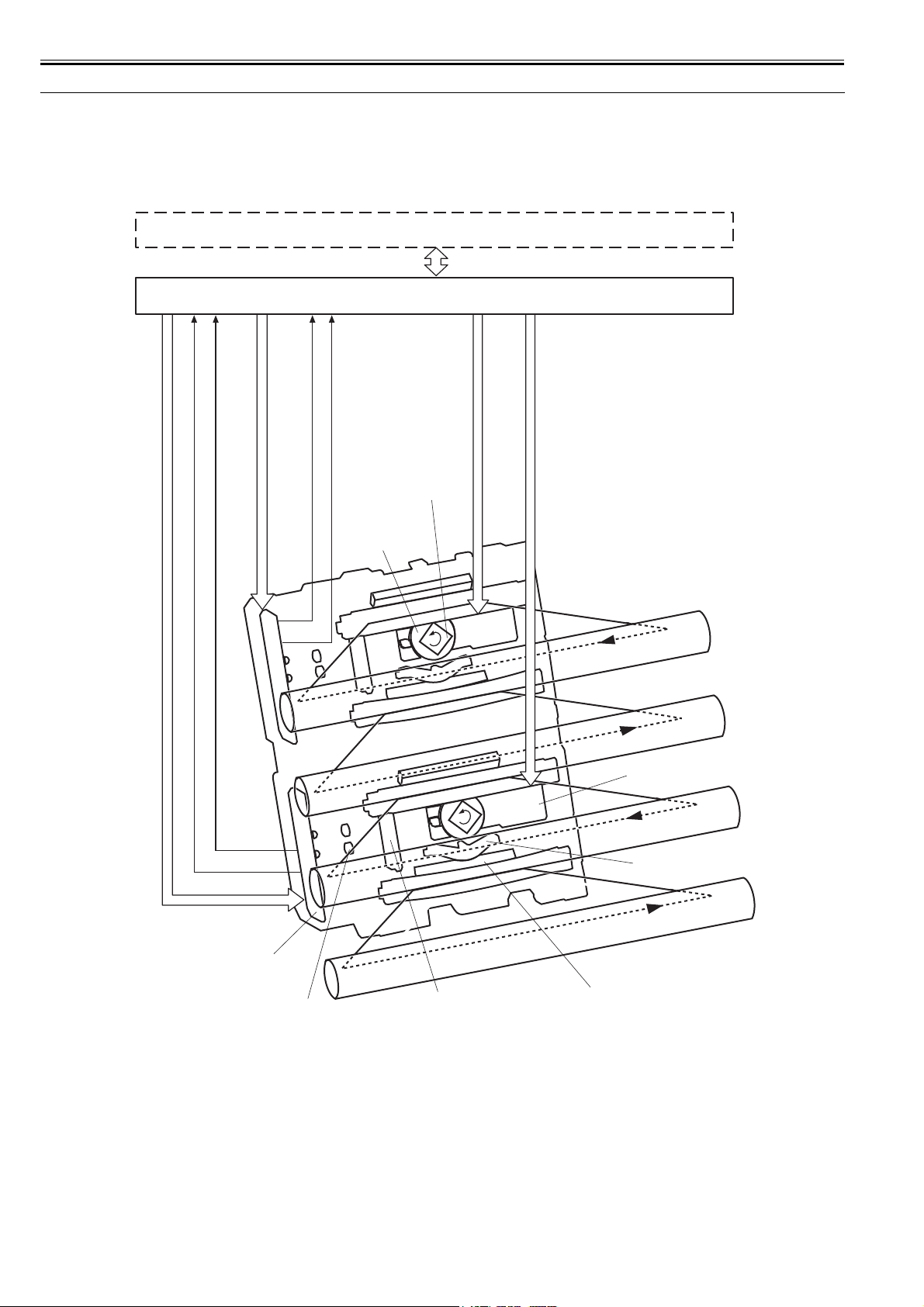
Chapter 2
2-2
2.3 LASER EXPOSURE SYSTEM
2.3.1 Overview/Configuration
2.3.1.1 Outline
0010-6044
The machine's laser/scanner system serves to form latent images on the photosensitive drum according to the video signals coming from the video controller PCB,
and its principal components include the laser driver PCB and the scanner motor.
These components are grouped as a laser scanner unit, and are controlled by the DC controller PCB.
F-2-2
Video controller
/BDI34
/SCNACC12, /SCNDEC12
/BDI12
LDCTRL10, LDCTRL11, LDCTRL20, LDCTRL21
VDO1, /VDO1, VDO2, /VDO2
/SCNACC22, /SCNDEC22
LDCTRL30, LDCTRL31, LDCTRL40, LDCTRL41
VDO3, /VDO3, VDO4, /VDO4
PDOUT3, PDOUT4
PDOUT1, PDOUT2
DC Controller
Laser driver PCB
Collimator lens
Cylindrical lens
Focusing lens
Scanner mirror
(4-faceted)
Scanner motor
Scanner driver PCB
Reflecting mirror
M
C
Y
Bk
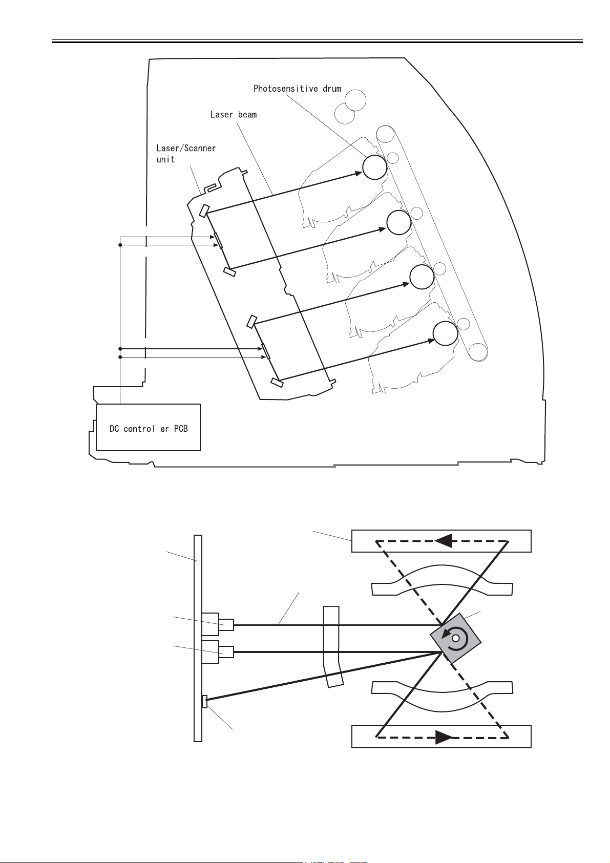
Chapter 2
2-3
F-2-3
The machine's laser/scanner unit is designed in such a way that a single scanner mirror is used to guide 2 laser beams (colors) at the same time (4-laser/2-mirror
method). Instead of the 4 scanner mirrors and scanner motors, the machine uses 2 mirrors and motors to perform the same mechanism, permitting the use of a smaller
laser unit and, ultimately, a smaller machine size.
The machine uses 4 laser diodes, 2 each on the 2 laser driver PCBs. It uses 2 scanner motors with a single scanner mirror reflecting 2 laser beams (colors).
F-2-4
The machine operates in the following sequence to execute a print job:
1) In response to the print command for the video controller PCB, the DC controller PCB rotates the scanner motor to turn the scanner mirror.
2) When the scanner motor starts to rotate, the DC controller PCB turns on the laser, and obtains /BD input signal from the BD sensor. The DC controller PCB finds
out the speed of rotation of the scanner motor with reference to the timing of the /BD input signal to make sure that the motor rotates at a specific speed of rotation.
3) When the speed of the scanner motor has stabilized, the laser driver PCB turns on the laser diodes according to the video signal.
Bk
Y
C
M
VDO4, /VDO4
VDO3, /VDO3
VDO2, /VDO2
VDO1, /VDO1
Laser driver PCB
BD sensor
Laser diode
(cyan)
Scanner mirror
Laser beam
Photosensitive drum
Laser diode
(magenta)
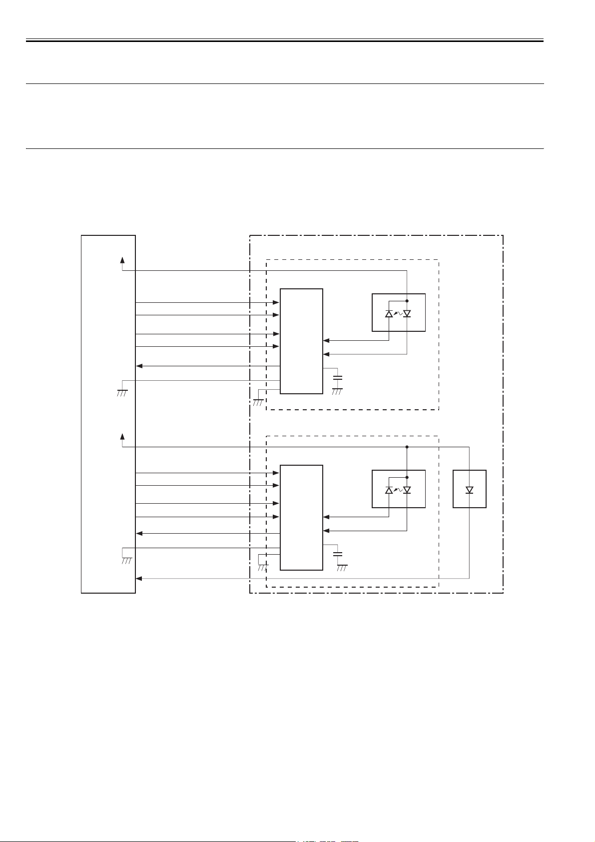
Chapter 2
2-4
4) The scanner mirror reflects the laser beam while rotating at a specific speed so that the beam scans the surface of the photosensitive drum at a corresponding speed.
5) When the photosensitive drum rotates at a specific speed and, in addition, the laser beam scans the surface of the photosensitive drum at a corresponding speed,
a latent image appears on the drum surface.
Note
1. Only one /BDI signal is generated to a scanner motor in this machine.
The /BDI signal to the scanner motor for M/C is generated by the reflection light from M laser, while the BDI signal to the scanner motor for Y/Bk is generated by
the reflection light from Y laser. Based on the /BDI signal, the DC controller PCB generates BD signals for four colors and send them to the video controller
PCB.
2. The machine uses a mechanism in which a single scanner mirror is used for 2 colors; in other words, the direction of scanning differs between colors. (In respect
of the printed side of a print, M/Y starts at the right edge, while C/Bk starts at the left edge.)
2.3.2 Laser Control
2.3.2.1 Outline
0010-6046
The machine's laser control consists in turning on and off the laser diode by the laser driver according to the laser control signal from the DC controller.
The machine's laser drive PCB is either for M/C or for Y/Bk; both PCBs are identical, and here, the descriptions are of the control mechanism associated with M/C.
F-2-5
The DC controller sends video signals (VDO, /VDO, used to form images) and laser control signals (LDCTRL0, LDCTRL1, used to switch the operating mode of
the laser driver circuit) to individual laser driver ICs, which control the laser activation based on the combination of laser control signals.
The machine controls its laser activation in the following 4 modes as dictated by the laser control signals:
1. laser activation control (turns on or off the laser diode according to the video signal)
2. auto photo current control (APC; makes sure that the intensity of the laser diode is at a specific level)
3. horizontal sync control (makes sure that the laser write start point in image horizontal direction is correct)
4. image mask control (makes sure that the laser beam will not be turned on in the non-image area outside the unblocking period)
The laser current output signal (PDOUT) is an analog signal that is the result of conversion of laser light into a corresponding level of current. The DC controller
PCB sends the respective intensity information to the video controller, representing individual colors (laser beams), obtained from the PDOUT signal so that the
video controller PCB may execute PWM adjustment to suit the selected gradation.
2.3.2.2 Laser Emission Control
0011-1370
The machine turns on and off the laser diode (LD) according to video signals.
When the DC controller PCB switches the operating mode of the laser driver circuit to print mode, the machine turns on and off the laser diode (LD) at a specific
intensity as dictated by the video signal (VDO, /VDO) coming from the video control.
2.3.2.3 Automatic power control (APC)
0011-1371
The machine makes sure that the intensity of the laser diode (LD) remains at a specific level at all times.
The APC mechanism may be either initial APC or between-line APC, and both are controlled by the laser driver circuit as follows:
1) When the DC controller PCB switches the operating mode of the laser driver circuit to LD forced activation mode, the laser driver circuit forces the LD to go on.
2) A photodiode (PD) checks the intensity of the LD, and converts it into a voltage; it is then compared against the reference voltage (equivalent of the target laser
DC controller PCB
Laser
driver
IC
VDO1
/VDO1
C107
J401A
-3
-3
-10
-9
-12
-11
-10
-9
-12
-11
LDPD
BD
circuit
PD
LD
IC101
PDOUT1
/BDI12
Laser driver PCB
-13-13
-15-15
Magenta laser driver circuit
LD101
Laser
driver
IC
C115
LDPD
PD
LD
IC102
Cyan laser driver circuit
LD102
VDO2
/VDO2
J401A
-1
-1
-5
-4
-7
-6
-5
-4
-7
-6
PDOUT2
-14-14
GND
-2-2
LDCTRL20
LDCTRL21
LDCTRL10
LDCTRL11
GND
-8-8
+5V
J112
+5V
J112
Loading...