


VG4 Modular Camera Series
VG4 Series
en Installation Manual

VG4 Modular Camera Series |
Table of Contents | en |
3 |
|
|
|
Table of Contents
1 |
Safety |
6 |
1.1 |
Important Safety Instructions |
6 |
1.2 |
Safety Precautions |
8 |
1.3 |
Important Safeguards for Pressurized Units |
8 |
1.4 |
Important Notices |
8 |
1.5 |
Customer Support and Service |
12 |
2 |
Installing the Pendant Arm Wall, Corner, and Mast (Pole) Mounts |
13 |
2.1 |
Unpacking |
13 |
2.1.1 |
Parts List |
13 |
2.1.2 |
Description |
15 |
2.1.3 |
Tools Required |
15 |
2.2 |
Pre-installation Checklist |
15 |
2.3 |
Mount Power Supply Box |
16 |
2.4 |
Route Wires and Attach Connectors |
17 |
2.4.1 |
Power Supply Box Connections |
20 |
2.5 |
Route Power through Intermediate Power Supply Box |
21 |
2.6 |
Attach Pendant Arm to Power Supply Box |
24 |
2.7 |
Make Connections in Power Supply Box |
25 |
2.8 |
Installing the VG4-A-ARMPLATE |
27 |
2.8.1 |
Attach the Pendant Arm to the Mounting Plate |
28 |
2.8.2 |
Route and Connect Wires to a Power Supply Box |
29 |
2.9 |
Assemble Pendant in Packing Box |
31 |
2.10 |
Attach Pendant to Arm and Tighten |
33 |
2.11 |
Installing the Pressurized Environmental Housing |
35 |
2.11.1 |
Important Installation Safeguards |
35 |
2.11.2 |
VG4 Pressurized Environmental Housing |
35 |
2.11.3 |
Required Equipment |
36 |
2.11.4 |
Attaching the Housing to the Arm |
37 |
2.11.5 |
Calibrating the Pressure Sensor |
38 |
2.11.6 |
Attaching the Bubble to the Housing |
39 |
2.11.7 |
Pressurizing the Housing |
41 |
2.11.8 |
Servicing the VG4 Pressurized Environmental Housing |
41 |
3 |
Installing Roof Parapet and Pipe Mounts |
42 |
3.1 |
Unpacking |
42 |
3.1.1 |
Parts List |
42 |
3.1.2 |
Description |
44 |
3.1.3 |
Tools Required |
44 |
3.2 |
Pre-installation Check List |
44 |
3.3 |
Mount Power Supply Box |
45 |
3.3.1 |
Attach Cover Door |
46 |
3.4 |
Route Wires and Attach Connectors |
47 |
3.4.1 |
Wiring the Power Supply Box |
49 |
3.4.2 |
Wiring the Fiber Optic Model |
49 |
3.4.3 |
Power Supply Box Connections |
51 |
Bosch Security Systems, Inc. |
Installation Manual |
F.01U.162.025 | 6.0 | 2010.03 |

4 en | Table of Contents VG4 Modular Camera Series
3.5 |
Installing the VG4-A-9230 Roof Parapet Mount |
52 |
3.6 |
Installing the VG4-A-9543 Pipe Mount |
55 |
3.7 |
Wire the Pipe Interface Board |
57 |
3.7.1 |
Wiring for Multiple AutoDomes |
58 |
3.7.2 |
Connecting Wires to the Pipe Interface Board |
58 |
3.8 |
Assemble the Pendant in Packing Box |
60 |
3.9 |
Attach Pendant to Pipe and Tighten |
62 |
3.10 |
Make Connections in the Power Supply Box |
63 |
3.10.1 |
Connections for Fiber Optic Models |
63 |
3.11 |
Installing the Pressurized Environmental Housing |
65 |
3.11.1 |
Important Installation Safeguards |
65 |
3.11.2 |
VG4 Pressurized Environmental Housing |
65 |
3.11.3 |
Required Equipment |
66 |
3.11.4 |
Attaching the Housing to the Pipe |
67 |
3.11.5 |
Make Connections in the Power Supply Box |
68 |
3.11.6 |
Calibrating the Pressure Sensor |
69 |
3.11.7 |
Attaching the Bubble to the Housing |
70 |
3.11.8 |
Pressurizing the Housing |
72 |
3.11.9 |
Servicing the Pressurized Environmental Housing installation |
72 |
|
|
|
4 |
Installing the In-Ceiling Mount |
73 |
4.1 |
Unpacking |
73 |
4.1.1 |
Parts List |
73 |
4.1.2 |
Description |
74 |
4.1.3 |
Tools Required |
74 |
4.2 |
Pre-installation Check List |
75 |
4.3 |
Dimensions |
75 |
4.4 |
Prepare Drywall Ceiling for Installation |
75 |
4.5 |
Prepare Suspension Ceiling for Installation |
76 |
4.6 |
Wire the Interface Box |
78 |
4.6.1 |
Interface Box Connections |
80 |
4.7 |
Attach Housing to the Interface Box |
81 |
4.8 |
Secure Housing to Ceiling |
82 |
4.9 |
Align and Install Camera Module |
83 |
4.10 |
Attach Bubble |
83 |
|
|
|
5 |
Cable and Wire Standards |
85 |
5.1 |
Power |
85 |
5.2 |
Wire Distance Guide for Pendant |
85 |
5.3 |
Video and Control Cables |
85 |
5.4 |
Control-only Cables |
88 |
5.5 |
Fiber Optic Module with an RS232/RS422 Controller |
92 |
5.5.1 |
Connecting to an LTC 4629 Head End Data/Video Transceiver |
92 |
5.5.2 |
Configuring the VG4 AutoDome |
93 |
F.01U.162.025 | 6.0 | 2010.03 |
Installation Manual |
Bosch Security Systems, Inc. |

VG4 Modular Camera Series Table of Contents | en 5
5.6 |
Audio Cables |
94 |
|
|
|
6 |
Alarms and Relay Connections |
96 |
6.1 |
Alarm Inputs |
96 |
6.2 |
Configuring Supervised Alarms (inputs 1 and 2) |
96 |
6.2.1 |
Configuring a Normally Open Supervised Alarm |
96 |
6.2.2 |
Configuring a Normally Closed Supervised Alarm |
97 |
6.3 |
Configuring Non-supervised Alarms (inputs 1 through 7) |
98 |
6.3.1 |
Configuring a Normally Open Non-supervised Alarm |
98 |
6.3.2 |
Configuring a Normally Closed Non-supervised Alarm |
98 |
6.4 |
Alarm Outputs |
99 |
6.4.1 |
Configuring a Dry Contact Relay |
99 |
6.4.2 |
Configuring an Open Collector Output |
99 |
|
|
|
7 |
Bubble Handling and Cleaning |
100 |
7.1 |
Handling |
100 |
7.2 |
Cleaning |
100 |
7.2.1 |
Cleaning the Bubble Interior |
100 |
7.2.2 |
Cleaning the Bubble Exterior |
100 |
|
|
|
A |
Installation Notes for AutoTracker |
101 |
A.1 |
Camera Height |
101 |
A.2 |
Mount/Mounting Surfaces |
102 |
A.3 |
Field of View |
102 |
A.4 |
Unwanted Motion |
102 |
|
|
|
|
Index |
103 |
Bosch Security Systems, Inc. |
Installation Manual |
F.01U.162.025 | 6.0 | 2010.03 |

6 |
en | Safety |
VG4 Modular Camera Series |
|
|
|
1 Safety
1.1 |
Important Safety Instructions |
Read, follow, and retain for future reference all of the following safety instructions. Heed all warnings on the unit and in the operating instructions before operating the unit.
1.Cleaning - Unplug the unit from the outlet before cleaning. Follow any instructions provided with the unit. Generally, using a dry cloth for cleaning is sufficient, but a moist fluff-free cloth or leather shammy may also be used. Do not use liquid cleaners or aerosol cleaners.
2.Heat Sources - Do not install the unit near any heat sources such as radiators, heaters, stoves, or other equipment (including amplifiers) that produce heat.
3.Ventilation - Any openings in the unit enclosure are provided for ventilation to prevent overheating and ensure reliable operation. Do not block or cover these openings. Do not place the unit in an enclosure unless proper ventilation is provided, or the manufacturer's instructions have been adhered to.
4.Water - Do not use this unit near water, for example near a bathtub, washbowl, sink, laundry basket, in a damp or wet basement, near a swimming pool, in an outdoor installation, or in any area classified as a wet location. To reduce the risk of fire or electrical shock, do not expose this unit to rain or moisture.
5.Object and liquid entry - Never push objects of any kind into this unit through openings as they may touch dangerous voltage points or short-out parts that could result in a fire or electrical shock. Never spill liquid of any kind on the unit. Do not place objects filled with liquids, such as vases or cups, on the unit.
6.Lightning - For added protection during a lightning storm, or when leaving this unit unattended and unused for long periods, unplug the unit from the wall outlet and disconnect the cable system. This will prevent damage to the unit from lightning and power line surges.
7.Controls adjustment - Adjust only those controls specified in the operating instructions. Improper adjustment of other controls may cause damage to the unit. Use of controls or adjustments, or performance of procedures other than those specified, may result in hazardous radiation exposure.
8.Overloading - Do not overload outlets and extension cords. This can cause fire or electrical shock.
9.Power cord and plug protection - Protect the plug and power cord from foot traffic, being pinched by items placed upon or against them at electrical outlets, and its exit from the unit. For units intended to operate with 230 VAC, 50 Hz, the input and output power cord must comply with the latest versions of IEC Publication 227 or IEC Publication 245.
10.Power disconnect - Units with or without ON/OFF switches have power supplied to the unit whenever the power cord is inserted into the power source; however, the unit is operational only when the ON/OFF switch is in the ON position. The power cord is the main power disconnect device for switching off the voltage for all units.
F.01U.162.025 | 6.0 | 2010.03 |
Installation Manual |
Bosch Security Systems, Inc. |

VG4 Modular Camera Series |
Safety | en |
7 |
|
|
|
11.Power sources - Operate the unit only from the type of power source indicated on the label. Before proceeding, be sure to disconnect the power from the cable to be installed into the unit.
–For battery powered units, refer to the operating instructions.
–For external power supplied units, use only the recommended or approved power supplies.
–For limited power source units, this power source must comply with EN60950. Substitutions may damage the unit or cause fire or shock.
–For 24 VAC units, voltage applied to the unit's power input should not exceed ±10%, or 28 VAC. User-supplied wiring must comply with local electrical codes (Class 2 power levels). Do not ground the supply at the terminals or at the unit's power supply terminals.
–If unsure of the type of power supply to use, contact your dealer or local power company.
12.Servicing - Do not attempt to service this unit yourself. Opening or removing covers may expose you to dangerous voltage or other hazards. Refer all servicing to qualified service personnel.
13.Damage requiring service - Unplug the unit from the main AC power source and refer servicing to qualified service personnel when any damage to the equipment has occurred, such as:
–the power supply cord or plug is damaged;
–exposure to moisture, water, and/or inclement weather (rain, snow, etc.);
–liquid has been spilled in or on the equipment;
–an object has fallen into the unit;
–unit has been dropped or the unit cabinet is damaged;
–unit exhibits a distinct change in performance;
–unit does not operate normally when the user correctly follows the operating instructions.
14.Replacement parts - Be sure the service technician uses replacement parts specified by the manufacturer, or that have the same characteristics as the original parts. Unauthorized substitutions may cause fire, electrical shock, or other hazards.
15.Safety check - Safety checks should be performed upon completion of service or repairs to the unit to ensure proper operating condition.
16.Installation - Install in accordance with the manufacturer's instructions and in accordance with applicable local codes.
17.Attachments, changes or modifications - Only use attachments/accessories specified by the manufacturer. Any change or modification of the equipment, not expressly approved by Bosch, could void the warranty or, in the case of an authorization agreement, authority to operate the equipment.
Bosch Security Systems, Inc. |
Installation Manual |
F.01U.162.025 | 6.0 | 2010.03 |

8 en | Safety VG4 Modular Camera Series
1.2 |
Safety Precautions |
|
|
|
DANGER! |
|
This symbol indicates an imminently hazardous situation such as “Dangerous Voltage” inside |
|
the product. If not avoided, this will result in an electrical shock, serious bodily injury, or |
|
death. |
|
|
|
|
|
WARNING! |
|
Indicates a potentially hazardous situation. If not avoided, this could result in serious bodily |
|
injury or death. |
|
|
|
|
|
CAUTION! |
|
Indicates a potentially hazardous situation. If not avoided, this may result in minor or |
|
moderate injury. Alerts the user to important instructions accompanying the unit. |
|
|
|
|
|
CAUTION! |
|
Indicates a potentially hazardous situation. If not avoided, this may result in property damage |
|
or risk of damage to the unit. |
|
|
|
|
|
NOTICE! |
|
This symbol indicates information or a company policy that relates directly or indirectly to the |
|
safety of personnel or protection of property. |
|
|
1.3 |
Important Safeguards for Pressurized Units |
|
– Always use safety goggles when servicing the unit. |
|
– Never use an unregulated gas supply to pressurize the enclosure. The valve should be |
|
regulated with a maximum of 70 kPa (10 psi) output. |
|
– PRESSURIZE USING DRY NITROGEN ONLY! |
|
|
|
CAUTION! |
|
Be sure to periodically examine the unit and its supporting structure. If the dome shows any |
|
signs of wear, such as stress cracking, it should be replaced immediately. |
|
|
1.4 Important Notices
Accessories - Do not place this unit on an unstable stand, tripod, bracket, or mount. The unit may fall, causing serious injury and/or serious damage to the unit. Use only with the cart, stand, tripod, bracket, or table specified by the manufacturer. When a cart is used, use caution and care when moving the cart/apparatus combination to avoid injury from tip-over. Quick stops, excessive force, or uneven surfaces may cause the cart/unit combination to overturn. Mount the unit per the manufacturer's instructions.
All-pole power switch - Incorporate an all-pole power switch, with a contact separation of at least 3 mm in each pole, into the electrical installation of the building.If it is needed to open the housing for servicing and/or other activities, use this all-pole switch as the main disconnect device for switching off the voltage to the unit.
Camera grounding - For mounting the camera in potentially damp environments, ensure to ground the system using the ground connection of the power supply connector (see section: Connecting external power supply).
F.01U.162.025 | 6.0 | 2010.03 |
Installation Manual |
Bosch Security Systems, Inc. |
VG4 Modular Camera Series |
Safety | en |
9 |
|
|
|
Camera lens - An assembled camera lens in the outdoor housing must comply and be tested in accordance with UL/IEC60950. Any output or signal lines from the camera must be SELV or Limited Power Source. For safety reasons the environmental specification of the camera lens assembly must be within the environmental specification of -10 °C (14 °F) to 50 °C (122 °F). Camera signal - Protect the cable with a primary protector if the camera signal is beyond 140 feet, in accordance with NEC800 (CEC Section 60).
Coax grounding:
–Ground the cable system if connecting an outside cable system to the unit.
–Connect outdoor equipment to the unit's inputs only after this unit has had its grounding plug connected to a grounded outlet or its ground terminal is properly connected to a ground source.
–Disconnect the unit's input connectors from outdoor equipment before disconnecting the grounding plug or grounding terminal.
–Follow proper safety precautions such as grounding for any outdoor device connected to this unit.
U.S.A. models only - Section 810 of the National Electrical Code, ANSI/NFPA No.70, provides information regarding proper grounding of the mount and supporting structure, grounding of the coax to a discharge unit, size of grounding conductors, location of discharge unit, connection to grounding electrodes, and requirements for the grounding electrode.
NOTICE!
This device is intended for use in public areas only.
U.S. federal law strictly prohibits surreptitious recording of oral communications.
Your Bosch product was developed and manufactured with high-quality material and components that can be recycled and reused. This symbol means that electronic and electrical appliances, which have reached the end of their working life, must be collected and
disposed of separately from household waste material. Separate collecting systems are usually in place for disused electronic and electrical products. Please dispose of these units at
 an environmentally compatible recycling facility, per European Directive 2002/96/EC. Environmental statement - Bosch has a strong commitment towards the environment. This unit has been designed to respect the environment as much as possible. Electrostatic-sensitive device - Use proper CMOS/MOS-FET handling precautions to avoid electrostatic discharge.
NOTE: Wear required grounded wrist straps and observe proper ESD safety precautions when handling the electrostatic-sensitive printed circuit boards.
Fuse rating - For security protection of the device, the branch circuit protection must be secured with a maximum fuse rating of 16A. This must be in accordance with NEC800 (CEC Section 60).
Grounding and polarization - This unit may be equipped with a polarized alternating current line plug (a plug with one blade wider than the other blade). This safety feature allows the plug to fit into the power outlet in only one way. If unable to insert the plug fully into the outlet, contact a locally certified electrician to replace the obsolete outlet. Do not defeat the safety purpose of the polarized plug.
Alternately, this unit may be equipped with a 3-pole grounding plug (a plug with a third pin for earth grounding). This safety feature allows the plug to fit into a grounded power outlet only. If unable to insert the plug into the outlet, contact a locally certified electrician to replace the obsolete outlet. Do not defeat the safety purpose of the grounding plug.
Moving - Disconnect the power before moving the unit. Move the unit with care. Excessive force or shock may damage the unit and the hard disk drives.
Bosch Security Systems, Inc. |
Installation Manual |
F.01U.162.025 | 6.0 | 2010.03 |

10 en | Safety |
VG4 Modular Camera Series |
|
|
Outdoor signals - The installation for outdoor signals, especially regarding clearance from power and lightning conductors and transient protection, must be in accordance with NEC725 and NEC800 (CEC Rule 16-224 and CEC Section 60).
Permanently connected equipment - Incorporate a readily accessible disconnect device in the building installation wiring.
Pluggable equipment - Install the socket outlet near the equipment so it is easily accessible. PoE - Never supply power via the Ethernet connection (PoE) when power is already supplied via the power connector.
Power disconnect - Units have power supplied whenever the power cord is inserted into the power source. The power cord is the main power disconnect for all units.
Power lines - Do not locate the camera near overhead power lines, power circuits, or electrical lights, nor where it may contact such power lines, circuits, or lights.
SELV
All the input/output ports are Safety Extra Low Voltage (SELV) circuits. SELV circuits should only be connected to other SELV circuits.
Because the ISDN circuits are treated like telephone-network voltage, avoid connecting the SELV circuit to the Telephone Network Voltage (TNV) circuits.
Video loss - Video loss is inherent to digital video recording; therefore, Bosch Security Systems cannot be held liable for any damage that results from missing video information. To minimize the risk of lost digital information, Bosch Security Systems recommends multiple, redundant recording systems, and a procedure to back up all analog and digital information.
NOTICE!
This is a class A product. In a domestic environment this product may cause radio interference, in which case the user may be required to take adequate measures.
FCC & ICES INFORMATION
(U.S.A. and Canadian Models Only, CLASS A)
This device complies with part 15 of the FCC Rules. Operation is subject to the following conditions:
–this device may not cause harmful interference, and
–this device must accept any interference received, including interference that may cause undesired operation.
Note
This equipment has been tested and found to comply with the limits for a Class A digital device, pursuant to Part 15 of the FCC Rules and ICES-003 of Industry Canada. These limits are designed to provide reasonable protection against harmful interference when the equipment is operated in a commercial environment. This equipment generates, uses, and radiates radio frequency energy and, if not installed and used in accordance with the instruction manual, may cause harmful interference to radio communications. Operation of this equipment in a residential area is likely to cause harmful interference, in which case the user will be required to correct the interference at his expense.
Intentional or unintentional modifications, not expressly approved by the party responsible for compliance, shall not be made. Any such modifications could void the user's authority to operate the equipment. If necessary, the user should consult the dealer or an experienced radio/television technician for corrective action.
The user may find the following booklet, prepared by the Federal Communications Commission, helpful: How to Identify and Resolve Radio-TV Interference Problems. This booklet is available from the U.S. Government Printing Office, Washington, DC 20402, Stock No. 004-000-00345-4.
F.01U.162.025 | 6.0 | 2010.03 |
Installation Manual |
Bosch Security Systems, Inc. |
VG4 Modular Camera Series |
Safety | en 11 |
|
|
INFORMATIONS FCC ET ICES (commercial applications)
(modèles utilisés aux États-Unis et au Canada uniquement, CLASSE A)
Ce produit est conforme aux normes FCC partie 15. la mise en service est soumises aux deux conditions suivantes:
–cet appareil ne peut pas provoquer d'interférence nuisible et
–cet appareil doit pouvoir tolérer toutes les interférences auxquelles il est soumit, y
compris les interférences qui pourraient influer sur son bon fonctionnement. AVERTISSEMENT: Suite à différents tests, cet appareil s’est révélé conforme aux exigences imposées aux appareils numériques de Classe A en vertu de la section 15 du règlement de la Commission fédérale des communications des États-Unis (FCC). Ces contraintes sont destinées à fournir une protection raisonnable contre les interférences nuisibles quand l'appareil est utilisé dans une installation commerciale. Cette appareil génère, utilise et émet de l'energie de fréquence radio, et peut, en cas d'installation ou d'utilisation non conforme aux instructions, générer des interférences nuisibles aux communications radio. L’utilisation de ce produit dans une zone résidentielle peut provoquer des interférences nuisibles. Le cas échéant, l’utilisateur devra remédier à ces interférences à ses propres frais.
Au besoin, l’utilisateur consultera son revendeur ou un technicien qualifié en radio/télévision, qui procédera à une opération corrective. La brochure suivante, publiée par la Commission fédérale des communications (FCC), peut s’avérer utile : « How to Identify and Resolve RadioTV Interference Problems » (Comment identifier et résoudre les problèmes d’interférences de radio et de télévision). Cette brochure est disponible auprès du U.S. Government Printing Office, Washington, DC 20402, États-Unis, sous la référence n° 004-000-00345-4. AVERTISSEMENT: Ce produit est un appareil de Classe A. Son utilisation dans une zone résidentielle risque de provoquer des interférences. Le cas échéant, l’utilisateur devra prendre les mesures nécessaires pour y remédier.
Disclaimer
Underwriter Laboratories Inc. (“UL”) has not tested the performance or reliability of the security or signaling aspects of this product. UL has only tested fire, shock and/or casualty hazards as outlined in UL's Standard(s) for Safety for Information Technology Equipment, UL 60950-1. UL Certification does not cover the performance or reliability of the security or signaling aspects of this product.
UL MAKES NO REPRESENTATIONS, WARRANTIES, OR CERTIFICATIONS WHATSOEVER REGARDING THE PERFORMANCE OR RELIABILITY OF ANY SECURITY OR SIGNALINGRELATED FUNCTIONS OF THIS PRODUCT.
Copyright
This user guide is the intellectual property of Bosch Security Systems, Inc. and is protected by copyright.
All rights reserved.
Trademarks
All hardware and software product names used in this document are likely to be registered trademarks and must be treated accordingly.
NOTICE!
This user guide has been compiled with great care and the information it contains has been thoroughly verified. The text was complete and correct at the time of printing. The ongoing development of the products may mean that the content of the user guide can change without notice. Bosch Security Systems accepts no liability for damage resulting directly or indirectly from faults, incompleteness or discrepancies between the user guide and the product described.
Bosch Security Systems, Inc. |
Installation Manual |
F.01U.162.025 | 6.0 | 2010.03 |

12 en | Safety VG4 Modular Camera Series
1.5 Customer Support and Service
If this unit needs service, contact the nearest Bosch Security Systems Service Center for authorization to return and shipping instructions.
Service Centers USA
Telephone: 800-366-2283 or 585-340-4162 Fax: 800-366-1329
Email: cctv.repair@us.bosch.com
Customer Service
Telephone: 888-289-0096 Fax: 585-223-9180
Email: security.sales@us.bosch.com
Technical Support
Telephone: 800-326-1450
Fax: 585-223-3508 or 717-735-6560 Email: technical.support@us.bosch.com
Repair Center
Telephone: 585-421-4220
Fax: 585-223-9180 or 717-735-6561 Email: security.repair@us.bosch.com
Canada
Telephone: 514-738-2434 Fax: 514-738-8480
Europe, Middle East & Asia Pacific Region
Telephone: 44 (0) 1495 274558 Fax: 44 (0) 1495 274280
Email: rmahelpdesk@solectron.com
More information
For additional information, please contact your Bosch Security Systems representative or visit our web site at www.boschsecurity.com
F.01U.162.025 | 6.0 | 2010.03 |
Installation Manual |
Bosch Security Systems, Inc. |

VG4 Modular Camera Series Installing the Pendant Arm Wall, Corner, and Mast (Pole) Mounts | en 13
2 |
Installing the Pendant Arm Wall, Corner, and Mast |
|||
|
(Pole) Mounts |
|
||
2.1 |
Unpacking |
|
||
|
|
This equipment should be unpacked and handled with care. If an item appears to have been |
||
|
|
damaged in shipment, notify the shipper immediately. |
|
|
|
|
Verify that all the parts listed in the Parts List below are included. If any items are missing, |
||
|
|
notify your Bosch Security Systems Sales or Customer Service Representative. See |
||
|
|
Section 1.5 Customer Support and Service, page 12 for contact information. |
|
|
|
|
The original packing carton is the safest container in which to transport the unit and must be |
||
|
|
used if returning the unit for service. Save it for possible future use. |
|
|
2.1.1 |
Parts List |
|
||
|
|
The following table lists the parts included with the Pendant Arm Wall, Corner, or Mast mount |
||
|
|
packages. |
|
|
|
|
|
|
|
|
|
Mount Kit Options |
Part Numbers |
|
|
|
|
|
|
|
|
Pendant Arm (Only) |
F01U010586 |
|
|
|
|
|
|
|
|
Pendant Arm with Mounting Plate |
VG4-A-ARMPLATE |
|
|
|
(24 V VG4 models only, no power supply box) |
|
|
|
|
|
|
|
|
|
Pendant Housing (with COMMS and CPU modules installed): |
|
|
|
|
– |
Analog VG4 AutoDome |
VG4-XXX-O or -S |
|
|
– |
IP-enabled AutoDome |
VG4-XXX-E |
|
|
|
|
|
|
|
Optional Housing Modules |
|
|
|
|
– |
Environmental Shield |
VG4-MHSG-EX |
|
|
– |
Pressurized Environmental Housing |
VG4-MHSG-NX |
|
|
|
|
|
|
|
Pendant Arm with one of the following Power Supply Boxes: |
|
|
|
|
|
|
|
|
|
– Power Box without transformer (24 VAC) |
VG4-A-PA0 |
|
|
|
|
|
|
|
|
– Power Box with 120 VAC transformer |
VG4-A-PA1 |
|
|
|
|
or with 230 VAC transformer |
VG4-A-PA2 |
|
|
|
|
|
|
|
– Power Box without transformer with Fiber Optic Module (24 VAC) |
VG4-A-PA0F |
|
|
|
|
|
|
|
|
– Power Box with 120 VAC transformer and Fiber Optic Module |
VG4-A-PA1F |
|
|
|
|
or with 230 VAC transformer and Fiber Optic Module |
VG4-A-PA2F |
|
|
|
|
|
|
|
Trim Skirt Power Supply Box |
F01U005225 |
|
|
|
|
|
|
|
|
Corner Mount Kit |
|
|
|
|
|
|
|
|
|
– |
Corner Mount Plate |
VG4-A-9542 |
|
|
|
|
|
|
|
Mast (Pole) Mount Kit |
|
|
|
|
|
|
|
|
|
– |
Mast Mount Plate |
VG4-A-9541 |
|
|
|
|
|
|
|
Bubble |
|
|
|
|
|
|
|
|
|
– Clear Bubble with white trim ring, or |
VG4-SBUB-PCL |
|
|
|
– Tinted Bubble with white trim ring |
VG4-SBUB-PTI |
|
|
|
– Optional white bubble support ring for Pressurized Environmental |
|
|
|
|
|
Housing |
|
|
|
|
|
|
Bosch Security Systems, Inc. |
Installation Manual |
F.01U.162.025 | 6.0 | 2010.03 |
14 en | Installing the Pendant Arm Wall, Corner, and Mast (Pole) Mounts |
VG4 Modular Camera Series |
|
|
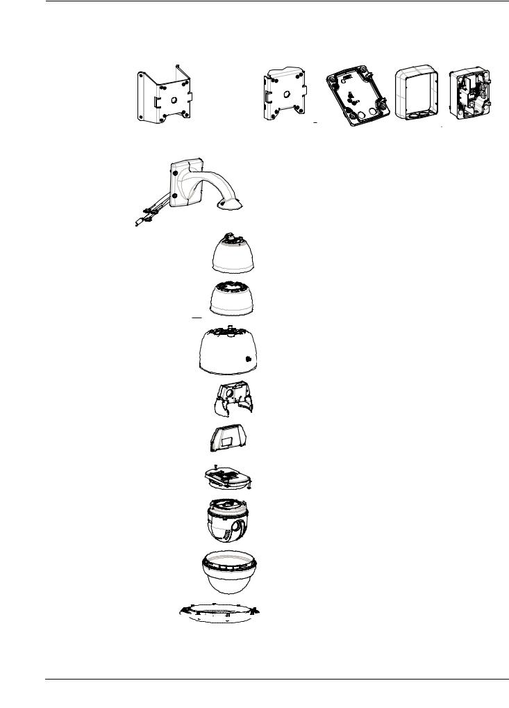
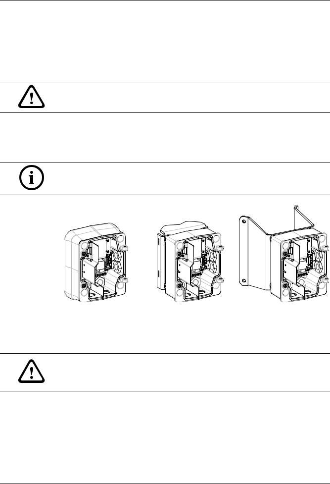
The following figures depict the parts (some optional) for a pendant arm wall, corner, or mast mount.
Corner Plate |
Mast Plate |
Mounting Plate Trim Skirt |
Power Supply |
|
(optional) |
(optional) |
(optional) |
(optional) |
|
Pendant Arm
Pendant Housing
Environmental Shield (optional)
Pressurized Environmental Housing (optional)
Heater Module (optional)
COMMS
Module
CPU Module
Camera
Module
Dome Bubble


 Bubble Support Ring for Pressurized Environmental Housing
(optional)
F.01U.162.025 | 6.0 | 2010.03 |
Installation Manual |
Bosch Security Systems, Inc. |
VG4 Modular Camera Series Installing the Pendant Arm Wall, Corner, and Mast (Pole) Mounts | en 15
2.1.2 |
Description |
|
Chapter 2 details how to install an AutoDome Pendant Arm to a wall, a corner, or to a mast |
|
(pole). Any variations to the installation procedures are noted. |
|
See Chapter 3 for a Roof (Parapet) or Pipe mount installation or Chapter 4 for an In-Ceiling |
|
mount installation. |
2.1.3 |
Tools Required |
|
– 5 mm Allen wrench (supplied) |
|
– Small, straight-blade screwdriver - 2.5 mm (0.1 in.) |
|
– No. 2 Phillips screwdriver |
|
– Socket wrench and 9/16-in. socket |
|
– Banding tool (Bosch P/N TC9311PM3T) - if installing a mast (pole) mount |
|
– 3/4 in. (20-mm) NPS right angle conduit connector - if installing a mast (pole) mount with |
|
a VG4-ARMPLATE |
|
– Pin-in Torx tool (supplied) or a T25 pin-in Torx driver (for Pressurized Environmental |
|
Housing) |
|
– Dial-indicator Torque Screwdriver (for Pressurized Environmental Housing) |
2.2 |
Pre-installation Checklist |
|
|
1. |
Determine the location and distance for the Power Supply Box based on its voltage and |
|
|
current consumption. |
|
|
You may choose to route the main power supply through an intermediate VG4 power |
|
|
supply box (VG4-PSU1 or VG4-PSU2) before connecting the power to the pendant arm |
|
|
power supply box (VG4-PA0). See Section 5 Cable and Wire Standards, page 85, for wiring |
|
|
information and distances. |
|
2. |
Use only UL listed liquid tight strain reliefs for conduits to the Power Supply Box to |
|
|
ensure that water cannot enter the box. You must use water tight conduits and fittings to |
|
|
meet NEMA 4 standards. |
WARNING!
Power and I/O cabling must be routed separately inside different permanently earthed metal conduits.
3.Route all rough wiring including: power, control, video coax, alarms I/O, relay I/O, and fiber optic cabling. See Section 5 Cable and Wire Standards, page 85, for video and control protocol methods.
WARNING!
Install external interconnecting cables in accordance to NEC, ANSI/NFPA70 (for US application) and Canadian Electrical Code, Part I, CSA C22.1 (for CAN application) and in accordance to local country codes for all other countries.
Branch circuit protection incorporating a 20 A, 2-pole Listed Circuit Breaker or Branch Rated Fuses are required as part of the building installation. A readily accessible 2-pole disconnect device with a contact separation of at least 3 mm must be incorporated.
4.Choose the appropriate AutoDome model (indoor or outdoor) for the environment in which it will be used.
5.If this AutoDome installation utilizes the AutoTracker feature, refer to
Section A Installation Notes for AutoTracker, page 101, before mounting the AutoDome.
Bosch Security Systems, Inc. |
Installation Manual |
F.01U.162.025 | 6.0 | 2010.03 |
16 en | Installing the Pendant Arm Wall, Corner, and Mast (Pole) Mounts |
VG4 Modular Camera Series |
|
|
6.Choose the appropriate mounting kit to use, depending on the location of the AutoDome, either wall mount, corner mount, or mast (pole) mount.
If the kit contains a Power Supply Box, refer to Section 2.3 Mount Power Supply Box, page 16.
If you are using the Mounting Plate with a 24 V VG4 AutoDome, refer to
Section 2.8 Installing the VG4-A-ARMPLATE, page 27.
CAUTION!
Select a rigid mounting location to prevent excessive vibration to the AutoDome camera.
2.3 Mount Power Supply Box
Before mounting the Power Supply Box decide if you should wire the box through the holes in the bottom or back of the box. If wiring the box through the back, move the two (2) seal plugs to the bottom through the holes before mounting.
NOTICE! Use 3/4-inch (20-mm) NPS fittings for the holes on the bottom and back of the box. Use 1/2-inch (15-mm) NPS fittings for the side holes.
Figure 2.1 Power Supply Wall, Mast (Pole), and Corner Mounts
1.Use the wall mount template supplied in the packaging box to locate the four mounting holes for the Power Supply Box.
2.Drill four (4) holes for the mounting anchors. If installing outdoors, apply a weatherproof sealant around each hole at the mounting surface.
WARNING!
A stud diameter of 6.4 mm (1/4 inch) to 8 mm (5/16 inch) able to withstand a 120 kg (265 lb) pull-out force is recommended. The mounting material must be able to withstand this pull out force. For example, 19-mm (3/4-inch) minimum for plywood.
3.Place the Power Supply Box into the optional Trim Skirt.
F.01U.162.025 | 6.0 | 2010.03 |
Installation Manual |
Bosch Security Systems, Inc. |
VG4 Modular Camera Series Installing the Pendant Arm Wall, Corner, and Mast (Pole) Mounts | en 17
4. Secure the Power Supply Box to the mounting surface.
– For a Wall installation: Use four (4) corrosion-resistant, stainless steel studs (not supplied). Then proceed to Step 5 below.
– For a Corner installation: Secure the Corner Plate to the wall corner using four (4) studs (not included). Then proceed to Step 5 below.
– For a Mast or a pole installation: The metal straps included with the Mast mount accommodate a pole with a diameter of 100–380 mm (4–15 in.). You must use a banding tool (sold separately) for a mast or pole installation. Follow the instructions provided with the banding tool to securely mount the Mast Plate to the pole. Contact your Bosch Sales Representative to order Banding Tool P/N TC9311PM3T.
5. Secure the Power Supply Box to the Corner Plate or Mast Plate using the four (4) 3/8 x 1- 3/4-inch bolts and split lock washers (supplied).
6. Attach 3/4-inch (20-mm) NPS watertight pipe fittings (not supplied) to the bottom or back holes of the Power Supply Box through which you will run the power, video, and control data wires.
2.4 Route Wires and Attach Connectors
Power wires must be routed to the left (front) side of the Power Supply Box through a separate conduit. All video, control, and alarm wires must be routed through a second conduit to the right side of the box.
If you plan to route the power through an intermediate power supply box, refer to
Section 2.5 Route Power through Intermediate Power Supply Box, page 21.
WARNING!
External interconnecting cables are to be installed in accordance to NEC, ANSI/NFPA70 (for US application) and Canadian Electrical Code, Part I, CSA C22.1 (for CAN application) and in accordance to local country codes for all other countries.
Branch circuit protection incorporating a 20 A, 2-pole Listed Circuit Breaker or Branch Rated Fuses are required as part of the building installation. A readily accessible 2-pole disconnect device with a contact separation of at least 3 mm must be incorporated.
J101
XF101 |
P101 |
24V NC 24V |
P106
J102 |
HTRDOME |
XF103 |
|
24 VAC |
P107 |
3452 1 |
|
|
|
J103 |
XF102 |
|
|
(LED) |
|
P105 |
|
|
|
GND TXD RXD |
C+ C- |
GND TXD RXD C+ C-
Figure 2.2 Pendant Arm Power Supply Box
Bosch Security Systems, Inc. |
Installation Manual |
F.01U.162.025 | 6.0 | 2010.03 |

18 en | Installing the Pendant Arm Wall, Corner, and Mast (Pole) Mounts |
VG4 Modular Camera Series |
|
|
1.Route all video, control, and alarm wires through the conduit fitting on the right side of the power box. See Section 5 Cable and Wire Standards, page 85, for coax, UTP, and fiber optic specifications and distances.
2.Route the high voltage 115/230 VAC lines through the conduit fitting on the left side of the box. The Power Supply Box with a transformer comes with a barrier that separates the high voltage side on the left, from the low voltage 24 VAC side on the right.
3.Cut and trim all wires with sufficient slack to reach their connector terminals in the box, but not so long as to be pinched by or to obstruct closing the Pendant Arm. See
Figure 2.2, Page 17, above, for the connector locations.
4.Attach the supplied 3-pin Power Plug to the incoming power wires. See connector P101 in Table 2.1, Page 21, for wire connections.
5.Attach the supplied 6-pin Control Data I/O Plug to the incoming control wires. See connector P106 in Table 2.1, Page 21, for wire connections. This step is not required with Fiber Optic models, since control passes through the fiber optic cable.
NOTICE! If “daisy chaining” a series of AutoDomes, a terminating resistor is required in the last dome of the series. The Bosch Power Supply Box is supplied with a 100 ? terminating resistor located between the Biphase terminals C- and C+ (pins 1 and 2) of the P106 control connector. Remove the resistor from all but the last AutoDome power box. The maximum number of AutoDomes that can be daisy chained is four (4). If using the RS485 protocol for control, the terminating resistor must be moved from the Biphase C+ and C- (pins 1 and 2) terminals to the RXDand TXD+ terminals (pins 4 and 5) of the P106 control connector of the last AutoDome power box.
6.Attach a BNC connector to the incoming video coax cable. If using UTP for video or installing an Ethernet model, attach an RJ45 plug to the incoming UTP cable. If installing a Fiber Optic model, attach an ST fiber plug to the optic fiber cable. See Section 5 Cable and Wire Standards, page 85, for the different methods of transmitting video and control protocols, and wire specifications.
F.01U.162.025 | 6.0 | 2010.03 |
Installation Manual |
Bosch Security Systems, Inc. |

VG4 Modular Camera Series |
Installing the Pendant Arm Wall, Corner, and Mast (Pole) Mounts | en 19 |
|
|
7.If you are connecting alarm inputs and outputs, attach the supplied 4- and 6-pin Alarm Connectors with flying lead wires to the appropriate incoming alarm wires.
PIN
1WHITE
2BROWN
3 |
|
P102 |
ORANGE |
|
|
4 |
|
|
GREEN |
|
PIN
1WHITE
2BROWN
3ORANGE
4 |
|
P103 |
GREEN |
5YELLOW
6BLUE
Figure 2.3 Alarm and relay connectors
.O.N |
1 |
|
.NCOM |
2 |
|
|
||
.C |
3 |
|
|
4 |
|
A1 |
5 |
|
|
||
A2 |
6 |
|
GND |
||
7 |
||
|
P104
1 |
4-pin Alarm Connector |
2 |
6-pin Alarm In Connector |
3 |
7-pin Relay Connector |
|
(P102) |
|
(P103) |
|
(P104) |
|
|
|
|
|
|
Pin |
Description |
Pin |
Description |
Pin |
Description |
1 |
Alarm Out 1 |
1 |
Alarm In 3 |
1 |
Normally Open |
2 |
Alarm Out 2 |
2 |
Alarm In 4 |
2 |
COM |
3 |
Alarm Out 3‡ |
3 |
Alarm In 5 |
3 |
Normally Closed |
4 |
Alarm Ground |
4 |
Alarm In 6 |
4 |
Earth Ground |
|
|
5 |
Alarm In 7 |
5 |
Analog Alarm 1 |
|
|
6 |
Alarm Ground |
6 |
Analog Alarm 2 |
|
|
|
|
7 |
Ground |
‡ The Alarm Out 3 (on the P102 connector) is the dedicated low pressure alarm for VG4 100 Series AutoDome cameras.
8.If you are connecting supervised alarms and relays, attach the supplied 7-pin Relay Connector to the appropriate incoming wires. See Figure 2.3, Page 19, above, for the wire connections. See Section 6 Alarms and Relay Connections, page 96 for more details about wiring alarms and relays.
Bosch Security Systems, Inc. |
Installation Manual |
F.01U.162.025 | 6.0 | 2010.03 |

20 en | Installing the Pendant Arm Wall, Corner, and Mast (Pole) Mounts VG4 Modular Camera Series
2.4.1 Power Supply Box Connections
The following figure is a detailed illustration of the Pendant Arm Power Supply Box, which includes the fuse specifications.

 10J1
10J1

(FUSE) |
XF101 |
P101 |
24V NC 24V |
1 2 3
TRANSFORMER (115/230VAC MODELS)
|
|
|
|
|
J102 |
|
|
XF103 |
|
|
|
|
|
P107 |
HTR DOME |
5 4 3 2 1 |
|
|
|
|
|
|
J103 |
|
|
XF102 |
|
|
|
|
|
(LED) |
|
||
P106 |
|
|
P105 |
|
|
|
|
|
GND TXD RXD |
C+ |
C- |
GND TXD RXD |
C+ |
C- |
|
|
|
6 5 4 3 2 1 |
6 5 4 3 2 1 |
|
|
|
||||
(FUSE) (FUSE)

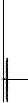


Figure 2.4 Pendant arm power supply box
|
1 |
Ground Screw |
7 |
P101 |
Connector; Power In |
|
2 |
From Harness |
8 |
P106 |
Connector; Control In/Out |
|
3 |
In/Out; 1/2 in. (15 mm) NPS Fitting |
9 |
P105 |
Connector; Control to Dome |
|
4 |
Video |
10 |
Power In; 3/4 in. (20 mm) NPS Fitting |
|
|
5 |
24 VAC to Dome |
11 |
Control Data and Video In/Out; 3/4 in. (20 mm) |
|
|
|
|
|
NPS Fitting |
|
|
|
|
|
|
|
|
6 |
In/Out; 1/2 in. (15 mm) NPS Fitting |
|
|
|
|
|
|
|
|
|
WARNING!
Fuse replacement by qualified service personnel only. Replace with same type fuse.
Fuse Specifications
Volts |
XF101 Mains |
XF102 Camera |
XF103 Heater |
|
|
|
|
24 V |
T 5.0 A |
T 2.0 A |
T 3.15 A |
|
|
|
|
115 V |
T 1.6 A |
T 2.0 A |
T 3.15 A |
|
|
|
|
230 V |
T 0.8A |
T 2.0 A |
T 3.15 A |
|
|
|
|
F.01U.162.025 | 6.0 | 2010.03 |
Installation Manual |
Bosch Security Systems, Inc. |
VG4 Modular Camera Series |
Installing the Pendant Arm Wall, Corner, and Mast (Pole) Mounts | en 21 |
|
|
The following table lists the Power Supply Box connectors:
|
|
No. |
|
Connector |
Pin 1 |
Pin 2 |
Pin 3 |
Pin 4 |
Pin 5 |
Pin 6 |
|
|
|
|
|
|
|
|
|
|
|
|
|
|
|
Ground |
Grounding Screw |
|
|
|
|
|
|
|
|
|
|
|
|
|
|
|
|
|
|
P101 |
|
115/230 VAC or |
Line |
NC |
Neutral |
|
|
|
|
|
|
|
24 VAC Power In |
|
|
|
|
|
|
|
|
|
|
|
|
|
|
|
|
|
|
|
P105 |
|
Control to Dome |
C- |
C+ |
Earth |
RXD (+) |
TXD (-) |
Signal |
|
|
|
|
(Arm Harness) |
(Biphase) |
(Biphase) |
Ground |
(RS-232/485) |
(RS-232/485) |
Ground |
|
|
|
|
|
|
|
|
|
|
|
|
|
P106 |
|
Control In/Out |
C- |
C+ |
Earth |
RXD (+) |
TXD (-) |
Signal |
|
|
|
|
|
(Biphase) |
(Biphase) |
Ground |
(RS-232/485) |
(RS-232/485) |
Ground |
|
|
|
|
|
|
|
|
|
|
|
|
|
P107 |
|
24 VAC Power |
Dome |
Dome |
Earth |
Heater |
Heater |
|
|
|
|
|
(Arm Harness) |
24 VAC |
24 VAC |
Ground |
(24 VAC) |
(24 VAC) |
|
|
|
|
|
|
|
|
|
|
|
|
|
|
Table 2.1 |
Power Supply Box Connections |
|
|
|
|
|
||
2.5 |
Route Power through Intermediate Power Supply Box |
|
||||||||
You may route the main power supply through a VG4-PSU1 (120 V transformer) or through a VG4-PSU2 (230 V transformer) Power Supply Box before connecting the power to a VG4-PA0 (24 V, no transformer) Power Supply Box. The main issue with this configuration is that the 5- pin power out connector from the VG4-PSU1 or VG4-PSU2 does not match to the 3-pin power input of the VG4-PA0 power supply. The illustration below depicts:
–A VG4-PSU1/VG4-PSU2 Power Supply Box.
–The main power supply connected to the P101 connector and to the grounding screw.
–The 24 VAC power out wire connected to the P107 heater power connectors.
VG4-PSU1 / VG4-PSU2
110J
(FUSE) |
XF101 |
P101 |
24V NC 24V |
1 2 3 |
P106 |
|
P105
J102 |
|
XF103 |
P107 |
DOME |
2 1 |
|
HTR |
|
|
J103 |
XF102 |
|
(LED) |
|
GND TXD RXD C+ C- |
GND TXD RXD C+ C- |
6 5 4 3 2 1 |
6 5 4 3 2 1 |
(FUSE) (FUSE)


Figure 2.5 VG4-PSU1/VG4-PSU2 Power Supply Box
1 |
120/230 VAC Power In |
5 |
Transformer |
2 |
Ground Wire |
6 |
In/Out Conduit (1/2 in. [15 mm] NPS Fitting |
3 |
P101 Connector |
7 |
24 VAC Power Out to VG4-PA0 |
4 |
P107 Connector |
|
|
Bosch Security Systems, Inc. |
Installation Manual |
F.01U.162.025 | 6.0 | 2010.03 |
22 en | Installing the Pendant Arm Wall, Corner, and Mast (Pole) Mounts VG4 Modular Camera Series
To properly wire the incoming high voltage and the outgoing low voltage lines, refer to this table:
No. |
|
Connector |
Pin 1 |
Pin 2 |
Pin 3 |
Pin 4 |
Pin 5 |
Pin 6 |
|
|
|
|
|
|
|
|
|
|
|
Ground |
Grounding Screw |
|
|
|
|
|
|
|
|
|
|
|
|
|
|
P101 |
|
115/230 VAC Power In |
Line |
NC |
Neutral |
|
|
|
|
|
|
|
|
|
|
|
|
P107 |
|
24 VAC Power Out |
|
|
Earth |
Heater |
Heater |
|
|
|
|
|
|
Ground |
(24 VAC) |
(24 VAC) |
|
|
|
|
|
|
|
|
|
|
Table 2.2 |
VG4-PSU1/VG4-PSU2 Power Supply Box Connections |
|
|
|
||||
1.Route the high voltage 115/230 VAC lines through the conduit fitting on the left side of the box. The Power Supply Box with a transformer comes with a barrier that separates the high voltage side on the left, from the low voltage 24 VAC side on the right.
2.Cut and trim the high voltage 115/230 VAC power and ground wires with sufficient slack to reach their connector terminal in the box, but not so long as to be pinched by or to obstruct closing the cover door.
3.Attach the supplied 3-pin power plug to the incoming high voltage power wires in the box. Refer to connector P101 in Table 2.2, Page 22 and to the image below for an illustration of these connections:
P101 |
24V NC 24V |
1 2 3
Figure 2.6 Incoming 115/230 VAC power supply
4.Attach the ground wire to the grounding screw.
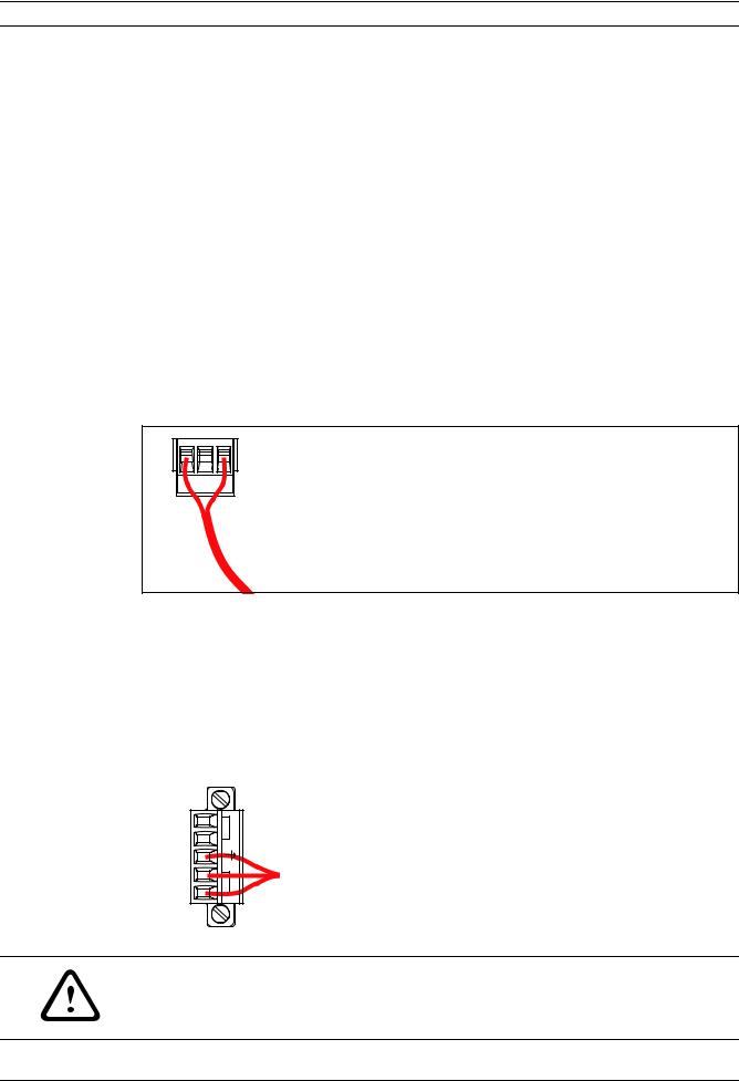
5.Connect three wires to the P107 Power Out connector to route the 24 VAC power supply to the VG4-PA0 Power Supply Box.
a.Connect the first wire to pin 5 (HN: Heater Neutral) connector.
b.Connect the second wire to pin 4 (HL: Heater Line) connector.
c.Connect the third wire to pin 3 (Earth Ground) connector.
Refer to connector P107 in Table 2.2 and to the image below for an illustration of these connections:
P107 |
HTR DOME |
5 4 3 2 1 |
Figure 2.7 Outgoing 24 VAC power supply
WARNING!
Ensure that you connect the outgoing power supply wires to the P107 heater connectors (HN and HL). The heater power (XF103) fuse can handle a higher amperage (3.15 A) than the camera power (XF102) fuse (2.0 A).
F.01U.162.025 | 6.0 | 2010.03 |
Installation Manual |
Bosch Security Systems, Inc. |
VG4 Modular Camera Series |
Installing the Pendant Arm Wall, Corner, and Mast (Pole) Mounts | en 23 |
|
|
6.Route the 24 VAC outgoing power supply wires into the VG4-PA0 power supply box through the conduit fitting on the left side of the box.
7.Cut and trim the 24 VAC power and ground wires with sufficient slack to reach their connector terminal in the box, but not so long as to be pinched by or to obstruct closing the cover door.
8.Attach the supplied 3-pin power plug to the incoming 24 VAC power wires in the box, as illustrated below.
101J
(FUSE) |
XF101 |
P101 |
24V NC 24V |
1 2 3
P1

 GND TXD RXD

 6 5
6 5 4
4
J102 |
|
XF103 |
P107 |
HTR DOME |
5 4 3 2 1 |
|
J103 |
XF102 |
|
(LED) |
|
C+ C-


 2 1
2 1
(FUSE) (FUSE)

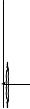


Figure 2.8 VG4-PA0 Power Supply Box
1 |
Incoming 24 VAC Power Supply Wires (from VG4-PSU1/VG4-PSU2 power supply box) |
2 |
Ground Wire |
3 |
P101 Connector |
4 |
Control Data and Video In/Out Wires |
9.Follow the instructions in Section 2.6 Attach Pendant Arm to Power Supply Box, page 24, to continue the installation.
Bosch Security Systems, Inc. |
Installation Manual |
F.01U.162.025 | 6.0 | 2010.03 |
24 en | Installing the Pendant Arm Wall, Corner, and Mast (Pole) Mounts VG4 Modular Camera Series
2.6 Attach Pendant Arm to Power Supply Box
The bottom hinge pin of the Pendant Arm is provided with a Hinge Pin Stop to hold the hinge open while attaching the arm to the Power Supply Box.
1.Compress the bottom hinge pin by pushing the pin lever downward and rotating it behind the Hinge Pin Stop.
Figure 2.9 Pendant Arm to Power Box Hinge Alignment
2.Open the top hinge by pushing its pin lever up and holding it.
NOTICE! Both Hinge Pins must be fully compressed to open (unlock) the hinges of the
Pendant Arm and before proceeding to the next step.
3.While continuing to hold the top hinge pin open and align the top and bottom hinges of the Pendant Arm to their mating points on the Power Supply Box. See Figure 2.9, above, for an illustration.
4.Once you have the hinges aligned, release the top hinge pin to engage its mating hinge on the power box. Then release the bottom hinge pin from the Hinge Pin Stop to lock the Pendant Arm to the Power Supply Box.
WARNING!
Serious injury or death can occur if the hinge pins of the Pendant Arm are not fully engaged (locked) to the Power Supply Box. Exercise caution before releasing the Pendant Arm.
F.01U.162.025 | 6.0 | 2010.03 |
Installation Manual |
Bosch Security Systems, Inc. |
VG4 Modular Camera Series Installing the Pendant Arm Wall, Corner, and Mast (Pole) Mounts | en 25
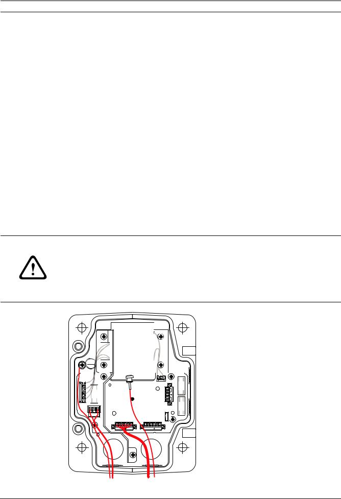
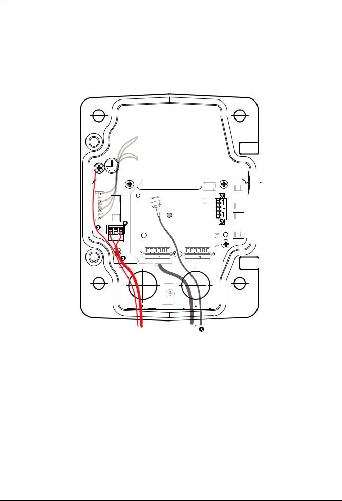
2.7 Make Connections in Power Supply Box
Refer to Table 2.2, Page 22 to locate the various connectors in the power supply box and make the following connections detailed below.
1 2 3 |
Figure 2.10 Pendant Arm connections to Power Supply Box
1.Attach the earth ground wire (item 1 in the illustration above) to the grounding screw on the left side of the power box.
2.Connect the 6-pin Control In/Out Plug, installed previously, to its mating connector P106 in the power box. If this product is a Fiber Optic model this step is not required, since all control data is sent through the fiber cable.
3.Connect the 6-pin Control to Dome Plug from the Pendant Connector Harness to its matting connector P105 in the power box. (For Fiber Optic model connect to the P106 connector.)
Control Data |
Coax Video |
24 VAC Power |
UTP Video/Ethernet |
|
Alarm Inputs |
Alarm Outputs |
Relays |
Grounding Strap |
|
|
|
|
WARNING! |
|
|
|
Do not connect the RJ45 connector unless using UTP video or Ethernet.
4.Connect the 5-pin, 24 VAC to Dome Plug from the Pendant Connector Harness to its corresponding color mating connector P107 on the right side of the box.
Bosch Security Systems, Inc. |
Installation Manual |
F.01U.162.025 | 6.0 | 2010.03 |

26 en | Installing the Pendant Arm Wall, Corner, and Mast (Pole) Mounts |
VG4 Modular Camera Series |
|
|
5.Connect the incoming video coax cable to the BNC connector from the Pendant Connector Harness and slide its plastic cover over the connector.
6.To connect alarm inputs and relay outputs, connect the 4-pin Alarms Out, the 6-pin Alarms In and the 7-pin Relay connectors from the Pendant Connector Harness to their mating connectors, installed previously, to the incoming alarm wires.
7.Connect the 3-pin Power In Plug, installed previously, to its matting connector P101 on the left side of the box.
8.If installing a Fiber Optic model attach the incoming ST fiber plug, installed previously, to its mating connector on the Fiber Optic Module in the power supply box. Then attach the video BNC plug to its mating connector from the Pendant Connector Harness. See
Section 5 Cable and Wire Standards, page 85 for fiber optic specifications.
FUSE) |
( |
24V NC 24V
|
|
|
DOME |
|
|
|
HTR |
GND TXD RXD |
|
C+ |
C- |


 (FUSE) (FUSE)


Figure 2.11 Optional Fiber Optic Module
1 |
Transformer |
5 |
In/Out |
2 |
BNC to Dome |
6 |
ST Connector (Fiber) |
3 |
In/Out |
7 |
Power In |
4 |
From Arm Harness |
8 |
Data In/Out |
F.01U.162.025 | 6.0 | 2010.03 |
Installation Manual |
Bosch Security Systems, Inc. |
VG4 Modular Camera Series |
Installing the Pendant Arm Wall, Corner, and Mast (Pole) Mounts | en 27 |
|
|
9.If using UTP for video or Ethernet, connect the incoming RJ45 video connector, installed previously, to its mating connector from the Pendant Connector Harness. See
Section 5 Cable and Wire Standards, page 85 for connections and specifications.
10.Attach the grounding strap of the Pendant Arm to the Power Supply Box. See Figure 2.10, Page 25.
11.After making the harness connections to the Power Supply Box, rotate the Pendant Arm to close and seal the Power Supply Box and tighten the two (2) captive screws to 10-12 N-m (90-105 in.-lbs).
12.Refer to Section 2.9 Assemble Pendant in Packing Box, page 31, to continue the VG4 AutoDome Installation procedure.
NOTICE! After all wiring is complete, close the cover door and tighten the two (2) captive screws on the cover door to 10-12 N-m (90-105 in.-lbs) to ensure the Power Supply Box is watertight.
2.8 |
Installing the VG4-A-ARMPLATE |
|
|
This section provides instructions to install a wall, corner, or mast mount with the VG4-A- |
|
|
ARMPLATE Mounting Plate instead of a Power Supply Box. |
|
|
|
|
|
CAUTION! |
|
|
You must route the main power supply through a 120/230 VAC transformer (VG4-PSU1 or |
|
|
VG4-PSU2 power supply box) before connecting the power to a 24 VAC AutoDome. |
|
|
|
|
|
|
|
|
WARNING! |
|
|
A stud diameter of 6.4 mm (1/4 inch) to 8 mm (5/16 inch) able to withstand a 120 kg (265 lb) |
|
|
pull-out force is recommended. The mounting material must be able to withstand this pull out |
|
|
force. For example, 19-mm (3/4-inch) minimum for plywood. |
|
|
|
|
|
1. For a Corner installation: |
|
|
a. |
Secure the Corner Plate to the wall corner using four (4) studs (not included). |
|
b. |
Secure the Mounting Plate to the Corner Plate using the four (4) 3/8 x 1-3/4-inch |
|
|
bolts and split lock washers (supplied). |
|
2. For a Mast or pole installation: |
|
|
The metal straps included with the Mast mount accommodate a pole with a diameter of |
|
|
100–380 mm (4–15 in.). You must use a banding tool (sold separately) for a mast or pole |
|
|
installation. In addition, you must obtain a 3/4 in. (20-mm) right angle conduit connector |
|
|
through which you route the wires that connect to the pendent arm. |
|
|
a. |
Follow the instructions provided with the banding tool to securely mount the Mast |
|
|
Plate to the pole. Contact your Bosch Sales Representative to order Banding Tool |
|
|
P/N TC9311PM3T. |
|
b. |
Secure the Mounting Plate to the Mast Plate using the four (4) 3/8 x 1-3/4-inch bolts |
|
|
and split lock washers (supplied). |
|
c. |
Remove one of the rubber gaskets from the Mounting Plate. |
Bosch Security Systems, Inc. |
Installation Manual |
F.01U.162.025 | 6.0 | 2010.03 |

28 en | Installing the Pendant Arm Wall, Corner, and Mast (Pole) Mounts |
VG4 Modular Camera Series |
|
|
d.Once the Mounting Plate (item 1, below) is attached to the Mast Plate (item 2), connect the right angle conduit (item 3) to the Mounting Plate through the empty conduit hole as shown below:
|
3. |
Ensure that the mounting plate is secure. |
||||
2.8.1 |
Attach the Pendant Arm to the Mounting Plate |
|||||
|
The bottom hinge pin of the Pendant Arm is provided with a Hinge Pin Stop to hold the hinge |
|||||
|
open while attaching the arm to the Mounting Plate. |
|||||
|
1. |
Compress the bottom hinge pin by pushing the pin lever downward and rotating it |
||||
|
|
behind the Hinge Pin Stop. |
||||
|
|
|
|
|
|
|
|
|
|
|
|
|
|
|
|
|
|
|
|
|
|
|
|
|
|
|
|
Figure 2.12 Connect Pendant Arm to Mounting Plate
F.01U.162.025 | 6.0 | 2010.03 |
Installation Manual |
Bosch Security Systems, Inc. |
VG4 Modular Camera Series Installing the Pendant Arm Wall, Corner, and Mast (Pole) Mounts | en 29
2. Open the top hinge by pushing its pin lever up and holding it.
Note: Both Hinge Pins must be fully compressed to open (unlock) the hinges of the Pendant Arm and before proceeding to the next step.
3. While continuing to hold the top hinge pin open, align the top and bottom hinges of the Pendant Arm to their mating points on the Mounting Plate. See Figure 2.12, above, for an illustration.
4. Once you have the hinges aligned, release the top hinge pin to engage its mating hinge on the Mounting Plate. Then release the bottom hinge pin from the Hinge Pin Stop to lock the Pendant Arm to the Mounting Plate.
2.8.2 |
Route and Connect Wires to a Power Supply Box |
|
The illustration below depicts the power and control cables connected to the Pendant Arm: |
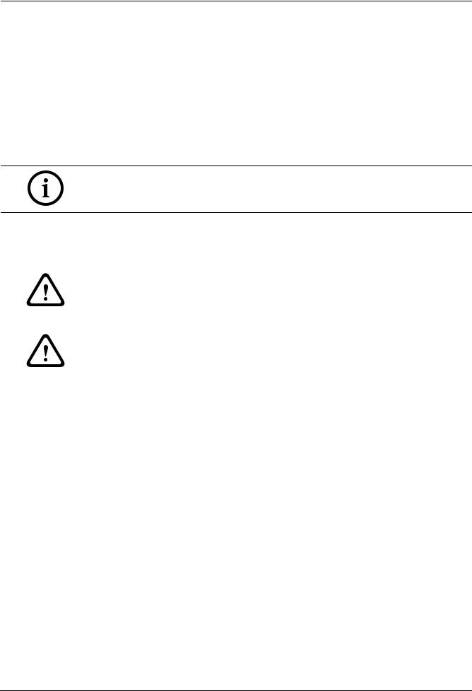
Figure 2.13 Pendant Arm Cables
Cable |
Cable |
Cable |
Cable |
1 |
Grounding Strap (black) |
5 |
UTP Video/Ethernet (blue) |
2 |
24 VAC Power (red) |
6 |
Alarm Outputs (white) |
3 |
Relay Contacts (yellow) |
7 |
Alarm Inputs (gray) |
4 |
Coax Video (black) |
8 |
Serial Communications (green) |
Bosch Security Systems, Inc. |
Installation Manual |
F.01U.162.025 | 6.0 | 2010.03 |
30 en | Installing the Pendant Arm Wall, Corner, and Mast (Pole) Mounts |
VG4 Modular Camera Series |
|
|
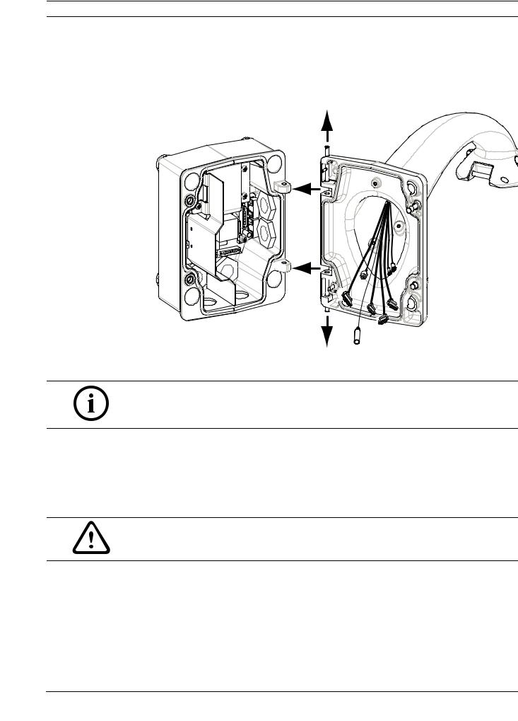
1.Route all incoming wires through one of the conduits at the bottom of the Mounting Plate. For a mast mount, route all wires through the right-angle conduit.
2.Attach the water-tight plug to the other conduit.
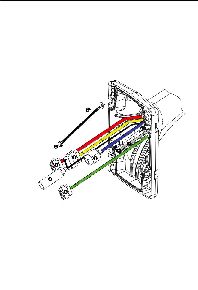
3.Attach the grounding spade terminal (item 1, below) to one of the spade terminals inside the Mounting Plate.
Figure 2.14 Mounting Plate - Inside Detail
Ref. |
Description |
1 |
Grounding lug with two spade terminals |
2 |
Earth ground lug with crimp ring terminal |
3 |
Wire input conduit holes |
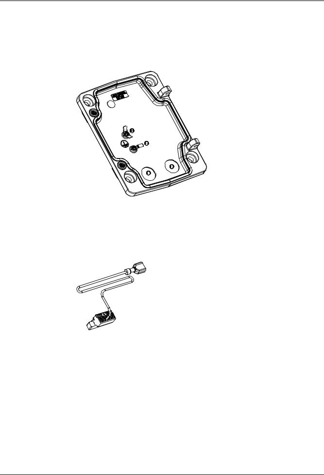
4.Connect the incoming 24 VAC power wires to the 5-pin, 24 VAC Power In mating connector (supplied with the Mounting Plate kit) for the Dome and for the Heater.
5.Attach the grounding spade from the 5-pin mating connector (item 1, Figure 2.14) to the other spade terminal inside the mounting plate.
6.Attach the 5-pin Power In mating connector to the 24 VAC Power cable (cable 2) connected to the pendant.
7.Remove the mating connector from the Relay Contacts cable (cable 3).
8.Connect the incoming relay contact wires to the mating connector. Then, reattach the mating connector to the Relay Contacts cable.
9.Connect the incoming video coax cable to the BNC connector (cable 4) and slide its plastic cover over the connector.
10.If using UTP for video or Ethernet, connect the incoming RJ45 video connector, installed previously, to the UTP Video/Ethernet cable (cable 5). Refer to Section 5 Cable and Wire Standards, page 85, for detailed wire and connection information.
11.Connect the outgoing alarm wires to the flying leads coming from the 4-pin Alarm Outputs cable (cable 6).
F.01U.162.025 | 6.0 | 2010.03 |
Installation Manual |
Bosch Security Systems, Inc. |
 Loading...