


RS720Q-E8-RS12
2U Rackmount Server
User Guide

E9847
Revised Edition V2
October 2014
Copyright © 2014 ASUSTeK COMPUTER INC. All Rights Reserved.
No part of this manual, including the products and software described in it, may be reproduced, transmitted, transcribed, stored in a retrieval system, or translated into any language in any form or by any means, except documentation kept by the purchaser for backup purposes, without the express written permission of ASUSTeK COMPUTER INC. (“ASUS”).
ASUS provides this manual “as is” without warranty of any kind, either express or implied, including but not limited to the implied warranties or conditions of merchantability or fitness for a particular purpose. In no event shall ASUS, its directors, officers, employees, or agents be liable for any indirect, special, incidental, or consequential damages (including damages for loss of profits, loss of business, loss of use or data, interruption of business and the like), even if ASUS has been advised of the possibility of such damages arising from any defect or error in this manual or product.
Specifications and information contained in this manual ae furnished for informational use only, and are subject to change at any time without notice, and should not be construed as a commitment by ASUS. ASUS assumes no responsibility or liability for any errors or inaccuracies that may appear in this manual, including the products and software described in it.
Product warranty or service will not be extended if: (1) the product is repaired, modified or altered, unless such repair, modification of alteration is authorized in writing by ASUS; or (2) the serial number of the product is defaced or missing.
Products and corporate names appearing in this manual may or may not be registered trademarks or copyrights of their respective companies, and are used only for identification or explanation and to the owners’ benefit, without intent to infringe.
ii

Contents
Notices ....................................................................................................................... |
vii |
REACH ....................................................................................................... |
vii |
Safety information.................................................................................................... |
viii |
Australia statement notice............................................................................... |
ix |
About this guide........................................................................................................... |
x |
Chapter 1: Product Introduction
1.1 |
System package contents......................................................................... |
1-2 |
|
1.2 |
Serial number label..................................................................................... |
1-3 |
|
1.3 |
System specifications................................................................................ |
1-4 |
|
1.4 |
Front panel features................................................................................... |
1-7 |
|
1.5 |
Rear panel features.................................................................................... |
1-8 |
|
|
RS720Q-E8-RS12........................................................................................ |
1-8 |
|
1.6 |
Internal features........................................................................................ |
1-11 |
|
1.7 |
LED information........................................................................................ |
1-12 |
|
|
1.7.1 |
Front panel LEDs....................................................................... |
1-12 |
|
1.7.2 |
HDD status LEDs....................................................................... |
1-13 |
Chapter 2: Hardware Information
2.1 |
Removing the server node....................................... |
2-2 |
|
2.2 |
Air Duct |
....................................................................................................... |
2-3 |
2.3 |
Central Processing ..................................................................Unit (CPU) |
2-4 |
|
|
2.3.1 ........................................................................ |
Installing the CPU |
2-5 |
|
2.3.2 .......................................................... |
Installing the CPU heatsink |
2-9 |
2.4 |
System memory........................................................................................ |
2-10 |
|
|
2.4.1 .................................................................................... |
Overview |
2-10 |
|
2.4.2 .............................................................. |
Memory Configurations |
2-10 |
2.5 |
Hard disk ........................................................................................drives |
2-13 |
|
2.6 |
Expansion ........................................................................................slots |
2-15 |
|
2.6.1PCI Express x16 slot (Gen3 x16 link) + x8 slot (Gen3 x8 link) .2-15
|
2.6.2 |
Removing the riser card............................................................. |
2-16 |
|
2.6.3 |
Installing an expansion card...................................................... |
2-17 |
|
2.6.4 |
Configuring an expansion card.................................................. |
2-19 |
|
2.6.5 |
Interrupt assignments................................................................ |
2-19 |
2.7 |
Removable/optional components........................................................... |
2-20 |
|
|
2.7.1 |
System fan ................................................................................ |
2-20 |
|
2.7.2 |
Power supply module................................................................ |
2-22 |
|
2.7.3 |
Installing an M.2 card................................................................. |
2-23 |
iii

Contents
Chapter 3: Installation options
3.1 Tool-less Friction Rail Kit..........................................................................3-2
Chapter 4: Motherboard information
4.1 |
Motherboard layout.................................................................................... |
4-2 |
|
|
4.1.1 |
Layout contents ........................................................................... |
4-3 |
4.2 |
Jumpers |
....................................................................................................... |
4-5 |
4.3 |
Internal connectors.................................................................................. |
4-11 |
|
4.4 |
Internal LEDs............................................................................................. |
4-17 |
|
4.5 |
Z10PH-D16 ......................................................................Golden Finger |
4-21 |
|
Chapter 5: BIOS setup
5.1 |
Managing and updating your BIOS........................................................... |
5-2 |
|
|
5.1.1 |
ASUS CrashFree BIOS 3 utility................................................... |
5-2 |
|
5.1.2 |
ASUS EZ Flash Utility.................................................................. |
5-3 |
|
5.1.3 |
BUPDATER utility........................................................................ |
5-4 |
5.2 |
BIOS setup program................................................................................... |
5-6 |
|
|
5.2.1 |
BIOS menu screen...................................................................... |
5-7 |
|
5.2.2 |
Menu bar...................................................................................... |
5-7 |
|
5.2.3 |
Menu items.................................................................................. |
5-8 |
|
5.2.4 |
Submenu items............................................................................ |
5-8 |
|
5.2.5 |
Navigation keys........................................................................... |
5-8 |
|
5.2.6 |
General help................................................................................ |
5-8 |
|
5.2.7 |
Configuration fields...................................................................... |
5-8 |
|
5.2.8 |
Pop-up window............................................................................ |
5-8 |
|
5.2.9 |
Scroll bar...................................................................................... |
5-8 |
5.3 |
Main menu................................................................................................... |
5-9 |
|
|
5.3.1 |
System Date [Day xx/xx/xxxx]..................................................... |
5-9 |
|
5.3.2 |
System Time [xx:xx:xx]................................................................ |
5-9 |
5.4 |
Advanced menu........................................................................................ |
5-10 |
|
|
5.4.1 |
ACPI Settings............................................................................ |
5-11 |
|
5.4.2 |
Smart Settings........................................................................... |
5-11 |
|
5.4.3 |
NCT6779D Super IO Configuration........................................... |
5-12 |
|
5.4.4 |
Onboard LAN I210 Configuration ............................................. |
5-13 |
|
5.4.5 |
Serial Port Console Redirection................................................. |
5-14 |
|
5.4.6 |
APM........................................................................................... |
5-17 |
|
5.4.7 |
PCI Subsystem Settings............................................................ |
5-18 |
iv

Contents
|
5.4.8 |
Network Stack Configuration..................................................... |
5-19 |
|
5.4.9 |
CSM Configuration.................................................................... |
5-20 |
|
5.4.10 |
Trusted Computing.................................................................... |
5-21 |
|
5.4.11 |
USB Configuration..................................................................... |
5-22 |
|
5.4.12 |
iSCSI Configuration................................................................... |
5-23 |
5.5 |
IntelRCSetup menu................................................................................... |
5-24 |
|
|
5.5.1 |
Processor Configuration............................................................ |
5-25 |
|
5.5.2 |
Advanced Power Management Configuration........................... |
5-27 |
|
5.5.3 |
Common RefCode Configuration............................................... |
5-28 |
|
5.5.4 |
QPI Configuration...................................................................... |
5-29 |
|
5.5.5 |
Memory Configuration............................................................... |
5-30 |
|
5.5.6 |
IIO Configuration........................................................................ |
5-33 |
|
5.5.7 |
PCH Configuration..................................................................... |
5-34 |
|
5.5.8 |
Miscellaneous Configuration...................................................... |
5-37 |
|
5.5.9 |
Server ME Configuration........................................................... |
5-37 |
|
5.5.10 |
Runtime Error Logging Support................................................. |
5-37 |
5.6 |
Server Mgmt menu................................................................................... |
5-38 |
|
5.7 |
Event Logs menu...................................................................................... |
5-43 |
|
|
5.7.1 |
Change Smbios Event Log Settings.......................................... |
5-43 |
|
5.7.2 |
View Smbios Event Log............................................................. |
5-44 |
5.8 |
Monitor menu............................................................................................ |
5-45 |
|
4.9 |
Security menu........................................................................................... |
5-46 |
|
5.10 |
Boot menu................................................................................................. |
5-49 |
|
5.11 |
Tool menu.................................................................................................. |
5-50 |
|
5.12 |
Exit menu................................................................................................... |
5-51 |
|
Chapter 6: RAID Configuration
6.1 |
Setting up RAID.......................................................................................... |
6-2 |
|
|
6.1.1 |
RAID definitions........................................................................... |
6-2 |
|
6.1.2 |
Installing hard disk drives............................................................ |
6-3 |
|
6.1.3 |
Setting the RAID item in BIOS..................................................... |
6-3 |
|
6.1.4 |
RAID configuration utilities........................................................... |
6-3 |
6.2 |
LSI Software RAID Configuration Utility................................................... |
6-4 |
|
|
6.2.1 |
Creating a RAID set..................................................................... |
6-5 |
|
6.2.2 |
Adding or viewing a RAID configuration.................................... |
6-11 |
|
6.2.3 |
Initializing the virtual drives........................................................ |
6-12 |
|
6.2.4 |
Rebuilding failed drives.............................................................. |
6-16 |
v

6.2.5 |
Checking the drives for data consistency.................................. |
6-18 |
6.2.6 |
Deleting a RAID configuration................................................... |
6-21 |
6.2.7 |
Selecting the boot drive from a RAID set................................... |
6-22 |
6.2.8 |
Enabling WriteCache................................................................. |
6-23 |
6.3Intel® Rapid Storage Technology enterprise
SATA Option ROM Utility......................................................................... |
6-24 |
|
6.3.1 |
Creating a RAID set................................................................... |
6-25 |
6.3.2 |
Deleting a RAID set................................................................... |
6-27 |
6.3.3 |
Resetting disks to Non-RAID..................................................... |
6-28 |
6.3.4Exiting the Intel® Rapid Storage Technology enterprise
|
|
SATA Option ROM utility........................................................... |
6-29 |
|
6.3.5 |
Rebuilding the RAID.................................................................. |
6-29 |
|
6.3.6 |
Setting the Boot array in the BIOS Setup Utility........................ |
6-31 |
6.4 |
Intel® Rapid Storage Technology enterprise (Windows)...................... |
6-32 |
|
|
6.4.1 |
Creating a RAID set................................................................... |
6-33 |
|
6.4.2 |
Changing a Volume Type.......................................................... |
6-35 |
|
6.4.3 |
Deleting a volume...................................................................... |
6-36 |
|
6.4.4 |
Preferences............................................................................... |
6-37 |
Chapter 7: Driver installation
7.1 |
RAID driver installation.............................................................................. |
7-2 |
|
|
7.1.1 |
Creating a RAID driver disk......................................................... |
7-2 |
|
7.1.2 |
Installing the RAID controller driver............................................. |
7-3 |
7.2 |
Management applications and utilities installation............................... |
7-13 |
|
7.3 |
Running the Support DVD ...................................................................... |
7-13 |
|
7.4 |
Intel® chipset device software installation............................................. |
7-17 |
|
7.5Installing the Intel® I350-AM1/I350-AM2/I210
|
X540-BT2 Gigabit Adapters driver.......................................................... |
7-19 |
7.6 |
VGA driver installation............................................................................. |
7-22 |
7.7 |
Intel® Rapid Storage Technology enterprise 4.0 installation................ |
7-24 |
Appendices
ASUS contact information...................................................................................... |
A-2 |
vi
Notices
Federal Communications Commission Statement
This device complies with Part 15 of the FCC Rules. Operation is subject to the following two conditions:
•This device may not cause harmful interference, and
•This device must accept any interference received including interference that may cause undesired operation.
This equipment has been tested and found to comply with the limits for a Class B digital device, pursuant to Part 15 of the FCC Rules. These limits are designed to provide reasonable protection against harmful interference in a residential installation. This equipment generates, uses and can radiate radio frequency energy and, if not installed and used
in accordance with manufacturer’s instructions, may cause harmful interference to radio communications. However, there is no guarantee that interference will not occur in a particular installation. If this equipment does cause harmful interference to radio or television reception, which can be determined by turning the equipment off and on, the user is encouraged to try to correct the interference by one or more of the following measures:
•Reorient or relocate the receiving antenna.
•Increase the separation between the equipment and receiver.
•Connect the equipment to an outlet on a circuit different from that to which the receiver is connected.
•Consult the dealer or an experienced radio/TV technician for help.
WARNING! The use of shielded cables for connection of the monitor to the graphics card is required to assure compliance with FCC regulations. Changes or modifications to this unit not expressly approved by the party responsible for compliance could void the user’s authority to operate this equipment.
Canadian Department of Communications Statement
This digital apparatus does not exceed the Class A limits for radio noise emissions from digital apparatus set out in the Radio Interference Regulations of the Canadian Department of Communications.
This Class A digital apparatus complies with Canadian ICES-003.
REACH
Complying with the REACH (Registration, Evaluation, Authorization, and Restriction of
Chemicals) regulatory framework, we publish the chemical substances in our products at
ASUS REACH website at http://csr.asus.com/english/REACH.htm.
vii
Safety information
Electrical Safety
•Before installing or removing signal cables, ensure that the power cables for the system unit and all attached devices are unplugged.
•To prevent electrical shock hazard, disconnect the power cable from the electrical outlet before relocating the system.
•When adding or removing any additional devices to or from the system, ensure that the power cables for the devices are unplugged before the signal cables are connected. If possible, disconnect all power cables from the existing system before you add a device.
•If the power supply is broken, do not try to fix it by yourself. Contact a qualified service technician or your dealer.
Operation Safety
•Any mechanical operation on this server must be conducted by certified or experienced engineers.
•Beforeoperatingtheserver,carefullyreadallthemanualsincludedwiththeserverpackage.
•Before using the server, ensure all cables are correctly connected and the power cables are not damaged. If any damage is detected, contact your dealer as soon as possible.
•To avoid short circuits, keep paper clips, screws, and staples away from connectors, slots, sockets and circuitry.
•Avoid dust, humidity, and temperature extremes. Place the server on a stable surface.
This product is equipped with a three-wire power cable and plug for the user’s safety. Use the power cable with a properly grounded electrical outlet to avoid electrical shock.
Lithium-Ion Battery Warning
CAUTION! Danger of explosion if battery is incorrectly replaced. Replace only with the same or equivalent type recommended by the manufacturer. Dispose of used batteries according to the manufacturer’s instructions.
CD-ROM Drive Safety Warning
CLASS 1 LASER PRODUCT
Heavy System
CAUTION! This server system is heavy. Ask for assistance when moving or carrying the system.
viii
DO NOT throw the motherboard in municipal waste. This product has been designed to enable proper reuse of parts and recycling. This symbol of the crossed out wheeled bin indicates that the product (electrical and electronic equipment) should not be placed in municipal waste. Check local regulations for disposal of electronic products.
DO NOT throw the mercury-containing button cell battery in municipal waste. This symbol of the crossed out wheeled bin indicates that the battery should not be placed in municipal waste.
Australia statement notice
From 1 January 2012 updated warranties apply to all ASUS products, consistent with the Australian Consumer Law. For the latest product warranty details please visit http:// support.asus.com. Our goods come with guarantees that cannot be excluded under the
Australian Consumer Law. You are entitled to a replacement or refund for a major failure and compensation for any other reasonably foreseeable loss or damage. You are also entitled
to have the goods repaired or replaced if the goods fail to be of acceptable quality and the failure does not amount to a major failure.
If you require assistance please call ASUS Customer Service 1300 2787 88 or visit us at http://support.asus.com
ix

About this guide
Audience
This user guide is intended for system integrators, and experienced users with at least basic knowledge of configuring a server.
Contents
This guide contains the following parts:
1.Chapter 1: Product introduction
This chapter describes the general features of the server, including sections on front panel and rear panel specifications.
2.Chapter 2: Hardware information
This chapter lists the hardware setup procedures that you have to perform when installing or removing system components.
3.Chapter 3: Installation options
This chapter describes how to install optional components into the barebone server.
4.Chapter 4: Motherboard information
This chapter gives information about the motherboard that comes with the server. This chapter includes the motherboard layout, jumper settings, and connector locations.
5.Chapter 5: BIOS information
This chapter tells how to change system settings through the BIOS Setup menus and describes the BIOS parameters.
6.Chapter 6: RAID configuration
This chapter tells how to change system settings through the BIOS Setup menus. Detailed descriptions of the BIOS parameters are also provided.
7Chapter 7: Driver installation
This chapter provides the instructions for installing the necessary drivers for different system components in both Linux® and Windows® Operating Systems.
x
Conventions used in this guide
To ensure that you perform certain tasks properly, take note of the following symbols used throughout this manual.
DANGER/WARNING: Information to prevent injury to yourself when trying to complete a task.
CAUTION: Information to prevent damage to the components when trying to complete a task
IMPORTANT: Instructions that you MUST follow to complete a task.
.
NOTE: Tips and additional information to help you complete a task.
Typography |
|
Bold text |
Indicates a menu or an item to select. |
Italics |
Used to emphasize a word or a phrase. |
<Key> |
Keys enclosed in the less-than and greater-than sign means |
|
that you must press the enclosed key. |
Example: <Enter> means that you must press the Enter or Return key.
<Key1> + <Key2> + <Key3> If you must press two or more keys simultaneously, the key names are linked with a plus sign (+).
Command |
Example: <Ctrl> + <Alt> + <Del> |
Means that you must type the command exactly as shown, then |
|
|
supply the required item or value enclosed in brackets. |
|
Example: At DOS prompt, type the command line: |
|
format A:/S |
References
Refer to the following sources for additional information, and for product and software updates.
1.ASUS Server Web-based Management (ASWM) user guide
This manual tells how to set up and use the proprietary ASUS server management utility.
2.ASUS websites
The ASUS websites worldwide provide updated information for all ASUS hardware and software products. Refer to the ASUS contact information.
xi

xii
Product introduction |
1 |
This chapter describes the general features of the chassis kit. It includes sections on front panel and rear panel specifications.

1.1System package contents
Check your system package for the following items.
Model Name |
RS720Q-E8-RS12 |
|
|
Chassis |
ASUS 2U Rackmount Chassis |
|
|
Motherboard |
ASUS Z10PH-D16 Server Board |
|
|
|
2 x 1620W Power Supply |
|
4 x PCIe Riser Card (RE8LE16R-R12D) |
|
2 x Front Panel Board (LED Board, FPB-R21A) |
|
2 x Power Supply Distribution Board (PDB-R21D) |
Component |
1 x Power Connection Board (PSB-R21A) |
|
1 x Backplane Board (BP12LX-R21A) |
|
1 x Midplane Board (MP8LX-R21A-M/E8) |
|
4 x System Fans (80mm x 38mm) |
|
12 x Hot-swappable 3.5” HDD trays* |
|
|
|
1 x ASUS RS720Q-E8-RS12 Support DVD (includes User Guide) |
|
1 x ASWM Enterprise SDVD |
|
1 x ASMB8-iKVM Support DVD |
Accessories |
8 x CPU Heatsinks |
|
1 x Bag of Screws |
|
2 x AC Power Cables |
|
1 x Friction Rail Kit |
*May vary according to region or territory
If any of the above items is damaged or missing, contact your retailer.
1-2 |
Chapter 1: Product introduction |

1.2Serial number label
Please take note of the product’s serial number. The Serial number contains 14 characters such as xxS0xxxxxxxxxx similar to the figure shown below.
You need to provide the correct serial number to the ASUS Technical Support team member if you need assistance or, when requesting support.
RS720Q-E8-RS12
xxS0xxxxxxxxxx
RS720Q-E8-RS12 |
1-3 |

1.3System specifications
The ASUS RS720Q-E8-RS12 is a 2U server system featuring the ASUS Z10PH-D16 Server Board. The server supports Intel® LGA 2011-3 Intel® Xeon® E5-2600 v3 product family plus other latest technologies through the chipsets onboard.
Model Name |
|
|
|
|
|
ASUS RS720Q-E8-RS12 |
|
|
|
|
|||||
Processor Support / |
1 x Socket LGA2011-3 |
||||||
System Bus |
|
Intel |
® |
Xeon |
® |
Processor E5-2600 v3 product family |
|
|
|
|
|
||||
Core Logic |
|
Intel® C610 PCH |
|||||
|
Fan Speed |
|
|
|
|
|
|
ASUS |
Control |
|
|
|
|
|
|
Features |
ASWM |
|
|
|
|
|
|
|
Enterprise |
|
|
|
|
|
|
|
Total Slots |
16 per node (4-channel per CPU, 8 DIMM per CPU) |
|||||
|
Capacity |
Maximum up to 512 GB per node |
|||||
|
|
DDR4 2133/1866/1600/1333* |
|||||
Memory |
Memory Type |
RDIMM/LR-DIMM/NVDIMM |
|||||
|
|
2133MT/s@1DPC only |
|||||
|
Memory Size |
4GB, 8 GB, 16GB, 32GB** (RDIMM) |
|||||
|
32GB, 64GB** (LRDIMM) |
||||||
|
|
||||||
|
Total PCI/ |
2 per node |
|
|
|||
Expansion |
PCI-E Slots |
|
|
||||
|
|
|
|
|
|||
|
1 x PCI-E x16 (Gen3 x16 link), LP, HL |
||||||
Slots |
Slot Type |
||||||
|
|
|
|
|
|||
|
1 x PCI-E x8 (Gen3 x8 link), proprietary*** |
||||||
|
|
||||||
|
|
Per Node: |
|
|
|||
|
|
Intel® C610 |
|
||||
|
|
6 x SATA 6Gb/s ports or |
|||||
|
SATA Controller |
5 x SATA 6Gb/s ports + 1 x M.2 connector |
|||||
Storage |
|
Intel® RSTe (For Windows® only; supports software RAID 0, |
|||||
|
1, 10 and 5) |
|
|||||
|
|
LSI MegaRAID driver supports software RAID 0, 1, and 10 |
|||||
|
|
(Windows® and Linux) |
|||||
|
|
Optional kits: |
|||||
|
SAS Upgrade |
ASUS PIKE 3008 8-port SAS 12G RAID card |
|||||
|
|
ASUS PIKE 3108 8-port SAS 12G HW RAID card |
|||||
*Refer to www.asus.com for the complete list of supported CPUs.
**Refer to ASUS Server AVL for latest update
***Supports the following ASUS add-on cards (optional)
PEM-FDR (56Gb/s FDR InfiniBand card)
PEB-10G/57840-2S (Dual Port 10 Gigabit/s Ethernet card) PEB-10G/57811-1S (Single Port 10 Gigabit/s Ethernet card)
(continued on the next page)
1-4 |
Chapter 1: Product introduction |

Model Name |
|
ASUS RS720Q-E8-RS12 |
|
|
|
|
|
HDD Bays |
I = internal |
12 x Hot-swap 3.5" HDD Bays |
|
A or S will be |
(3 x Hot-swap 3.5" HDD Bays per node) |
||
|
hot-swappable |
||
|
|
Per node: |
|
Networking |
LAN |
2 x Intel® I210AT |
|
|
|
1 x Management Port |
|
Graphic |
VGA |
Aspeed AST2400 32MB |
|
|
External USB |
2 x USB 3.0 |
|
|
Port |
||
|
|
||
Rear I/O |
VGA Port |
1 |
|
|
2 x GbE LAN |
||
Connectors |
RJ-45 |
||
|
|||
|
1 x Management LAN |
||
|
|
||
|
80 LED port |
1 |
|
|
Software |
ASWM Enterprise |
|
Management |
Out of Band |
|
|
Solution |
Remote |
On-board ASMB8-iKVM for KVM-over-IP |
|
|
Management |
|
|
|
|
|
|
|
|
Windows® Server 2008 R2 |
|
|
|
Windows® Server 2012 |
|
|
|
RedHat® Enterprise Linux |
|
|
|
SuSE® Linux Enterprise Server |
|
OS support |
|
CentOS |
|
|
VMware |
||
|
|
||
|
|
Citrix XenServer |
|
|
|
Please find the latest OS support from |
|
|
|
http://www.asus.com/ |
|
|
|
|
(continued on the next page)
RS720Q-E8-RS12 |
1-5 |
Model Name |
ASUS RS720Q-E8-RS12 |
|
Regulatory Compliance |
BSMI, CE, C-TICK, FCC (Class A) |
|
Dimension |
750 mm x 444 mm x 88 mm (2U) |
|
Net Weight Kg (CPU, DRAM, |
30 Kg |
|
and HDD not included) |
||
|
||
|
1 + 1 Redundant 1620W 80Plus Platinum PSU |
|
|
Ratings: |
|
Power Supply |
1000 W: 100-120Vac, 12-10A, 50-60Hz, Class 1 |
|
|
1200 W: 100-140Vac, 12-10A, 50-60Hz, Class 1 |
|
|
1620W: 180-240Vac, 10.5-8A, 50-60Hz, Class 1 |
|
|
Operating temperature: 10oC – 35oC |
|
Environment |
Non operating temperature: -40oC – 70oC |
|
|
Non operating humidity: 20% – 90% (Non condensing) |
Specifications are subject to change without notice.
1-6 |
Chapter 1: Product introduction |
1.4Front panel features
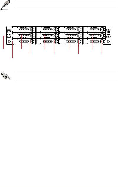
The barebone server displays easily accessible features such as the power and reset buttons, LED indicators, and optical drive.
Refer to the Front panel LEDs section for the LED descriptions.
Front panel |
|
|
|
|
|
|
|
|
|
|
|
|
|
|
|
||
Node 2 |
HDD 1 (Node 1) |
HDD 1 (Node 2) |
HDD 1 (Node 3) |
HDD 1 (Node 4) |
Front panel |
||||||||||||
|
|
|
|
|
|
|
|
|
|
|
|
|
|
|
Node 4 |
||
|
|
|
|
|
|
|
|
|
|
|
|
|
|
|
|
|
|
|
|
|
|
|
|
|
|
|
|
|
|
|
|
|
|
|
|
|
|
|
|
|
|
|
|
|
|
|
|
|
|
|
|
|
|
|
|
|
|
|
|
|
|
|
|
|
|
|
|
|
|
|
|
|
|
|
|
|
|
|
|
|
|
|
|
|
|
|
|
|
|
|
|
|
|
|
|
|
|
|
|
|
|
|
|
|
|
|
|
|
|
|
|
|
|
|
|
|
|
|
|
|
|
|
|
|
|
|
|
|
|
|
|
Front panel |
Front panel HDD 2 (Node 1) |
HDD 2 (Node 2) |
HDD 2 (Node 3) |
HDD 2 |
(Node 4) |
Node 3 |
|
Node 1 |
|
|
|
|
|
|
HDD 3 |
(Node 1) |
HDD 3 (Node 2) |
HDD 3 (Node 3) |
HDD 3 (Node 4) |
|
|
Asset tag |
|
|
|
|
|
|
Turn off the system power and detach the power supply before removing or replacing any system component.
Asset tag
The Asset tag is a small polyester film located on the bottom side of the server’s front panel.
It provides information about the server such as asset barcode or serial number and is useful in asset tracking and inventory management.
RS720Q-E8-RS12 |
1-7 |

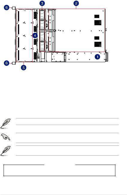
1.5Rear panel features
PSU 2
PSU 1 |
Node 4 |
Mgmt |
PORT80 |
Mgmt |
PORT80 |
Node 3 |
Node 2
Mgmt |
PORT80 |
Mgmt |
PORT80 |
Node 1
When installing only two nodes, install the nodes to node slot number 1 and 3 or number 2 and 4.
RS720Q-E8-RS12
RJ-45 port for iKVM
|
|
Mgmt |
|
|
|
|
|
|
|
PORT80 |
|
|
|
|
|
|
|
1 |
2 |
Location LED |
Message LED |
USB 3.0 ports |
Q-Code/Port 80 |
LAN 1 port |
|
|
|
|
LED |
|
|
|
||
|
|
|
|
|
LAN 2 port |
|
HDD Active LED |
VGA port |
|
Power button with LED |
|
||
|
|
|
||||
The ports for the USB, VGA, and Gigabit LANs do not appear on the rear panel if the motherboard is not present.
1.RJ-45 port for iKVM. This RJ45 port functios only when you enable ASMB8 controller.
2.USB 3.0 ports 1 and 2. These two 4-pin Universal Serial Bus (USB) ports are available for connecting USB 3.0 devices.
3.Video Graphics Adapter (VGA) port. This port is for a VGA monitor or other VGAcompatible devices.
4.Message LED. For details, refer to page 1-12.
5.Location LED. For details, refer to page 1-12.
6.HDD Active LED. For details, refer to page 1-13.
7.Power LED/button. Press this button to turn the system on/off.
1-8 |
Chapter 1: Product introduction |
8.LAN (RJ-45) ports 1 and 2. These ports allow Gigabit connection to a Local Area Network (LAN) through a network hub. Refer to the LAN port LED indications table for more information.
LAN port LED indications
Activity/Link LED |
|
Speed LED |
||
Status |
Description |
Status |
|
Description |
OFF |
No link |
OFF |
|
10 Mbps connection |
GREEN |
Linked |
ORANGE |
|
100 Mbps connection |
BLINKING |
Data activity |
GREEN |
|
1 Gbps connection |
ACT/LINK SPEED LED LED
9.Q-Code/Port 80 LED. The Q-Code LED provides a 2-digit display that shows the status of your system. Refer to the Q-Code table of this user guide for more information about the 2-digit codes.
Q-Code table
Action |
PHASE |
POST CODE |
TYPE |
DESCRIPTIONz |
|
|
01 |
Progress |
First post code(POWER_ON_POST_CODE) |
|
|
02 |
Progress |
Load BSP microcode(MICROCODE_POST_CODE) |
|
Security Phase |
03 |
Progress |
Set cache as ram for PEI phase(CACHE_ENABLED_POST_CODE) |
|
|
06 |
Progress |
CPU Early init.(CPU_EARLY_INIT_POST_CODE) |
|
|
04 |
Progress |
initializes South bridge for PEI preparation |
|
|
10 |
Progress |
PEI Core Entry |
|
|
15 |
Progress |
NB initialize before installed memory |
|
|
19 |
Progress |
SB initialize before installed memory |
|
|
78~00 |
Progress |
Wait BMC ready(duration: 120 seconds). |
|
|
A1 |
MRC Progress |
QPI initialization |
|
|
A3 |
MRC Progress |
QPI initialization |
|
|
A7 |
MRC Progress |
QPI initialization |
|
|
A8 |
MRC Progress |
QPI initialization |
|
|
A9 |
MRC Progress |
QPI initialization |
|
|
AA |
MRC Progress |
QPI initialization |
|
|
AB |
MRC Progress |
QPI initialization |
|
|
AC |
MRC Progress |
QPI initialization |
|
|
AD |
MRC Progress |
QPI initialization |
|
|
AE |
MRC Progress |
QPI initialization |
|
|
AF |
MRC Progress |
QPI initialization Complete |
Normal boot |
|
2F |
Progress |
Memory Init. |
|
B0 |
MRC Progress |
Memory Init. |
|
|
|
|||
|
P E I ( P r e - E F I |
B1 |
MRC Progress |
Memory Init. |
|
AF |
MRC Progress |
RC Reset if require |
|
|
initialization) phase |
|
|
|
|
B4 |
MRC Progress |
Memory Init. |
|
|
|
|||
|
|
B2 |
MRC Progress |
Memory Init. |
|
|
B3 |
MRC Progress |
Memory Init. |
|
|
B5 |
MRC Progress |
Memory Init. |
|
|
B6 |
MRC Progress |
Memory Init. |
|
|
B7 |
MRC Progress |
Memory Init. |
|
|
B8 |
MRC Progress |
Memory Init. |
|
|
B9 |
MRC Progress |
Memory Init. |
|
|
BA |
MRC Progress |
Memory Init. |
|
|
BB |
MRC Progress |
Memory Init. |
|
|
BC |
MRC Progress |
Memory Init. |
|
|
BF |
MRC Progress |
Memory Init. Done |
|
|
5A |
MRC Progress |
Other config. After RC end |
|
|
31 |
Progress |
Memory already installed. |
|
|
32 |
Progress |
CPU Init. |
|
|
34 |
Progress |
CPU Init. |
|
|
36 |
Progress |
CPU Init. |
|
|
4F |
Progress |
DXE Initial Program Load(IPL) |
(continued on the next page)
RS720Q-E8-RS12 |
1-9 |

Q-Code table
Action |
PHASE |
POST CODE |
TYPE |
DESCRIPTION |
|
|
60 |
Progress |
DXE Core Started |
|
|
61 |
Progress |
DXE NVRAM Init. |
|
|
62 |
Progress |
SB run-time init. |
|
|
63 |
Progress |
DXE CPU Init |
|
|
68 |
Progress |
NB Init. |
|
D X E ( D r i v e r |
69 |
Progress |
NB Init. |
|
E x e c u t i o n |
6A |
Progress |
NB Init. |
|
Environment) phase |
|||
|
|
70 |
Progress |
SB Init. |
|
|
71 |
Progress |
SB Init. |
|
|
72 |
Progress |
SB Init. |
|
|
78 |
Progress |
ACPI Init. |
|
|
79 |
Progress |
CSM Init. |
|
|
90 |
Progress |
BDS started |
|
|
91 |
Progress |
Connect device event |
|
|
92 |
Progress |
PCI Bus Enumeration. |
|
|
93 |
Progress |
PCI Bus Enumeration. |
|
|
94 |
Progress |
PCI Bus Enumeration. |
|
|
95 |
Progress |
PCI Bus Enumeration. |
|
|
96 |
Progress |
PCI Bus Enumeration. |
|
|
97 |
Progress |
Console outout connect event |
Normal boot |
|
98 |
Progress |
Console input connect event |
|
99 |
Progress |
AMI Super IO start |
|
|
|
|||
|
|
9A |
Progress |
AMI USB Driver Init. |
|
|
9B |
Progress |
AMI USB Driver Init. |
|
|
9C |
Progress |
AMI USB Driver Init. |
|
BDS(Boot Device |
9D |
Progress |
AMI USB Driver Init. |
|
Selection) phase |
b2 |
Progress |
Legacy Option ROM Init. |
|
|
b3 |
Progress |
Reset system |
|
|
b4 |
Progress |
USB hotplug |
|
|
b6 |
Progress |
NVRAM clean up |
|
|
b7 |
Progress |
NVRAM configuration reset |
|
|
A0 |
Progress |
IDE, AHCI Init. |
|
|
A1 |
Progress |
IDE, AHCI Init. |
|
|
A2 |
Progress |
IDE, AHCI Init. |
|
|
A3 |
Progress |
IDE, AHCI Init. |
|
|
A8 |
Progress |
BIOS Setup Utility password verify |
|
|
A9 |
Progress |
BIOS Setup Utility start |
|
|
AB |
Progress |
BIOS Setup Utility input wait |
|
|
AD |
Progress |
Ready to boot event |
|
|
AE |
Progress |
Legacy boot event |
|
Operating system |
AA |
Progress |
APIC mode |
|
phase |
AC |
Progress |
PIC mode |
1-10 |
Chapter 1: Product introduction |
1.6Internal features
The barebone server includes the basic components as shown.
1.2 x Power supply and power fan
2.ASUS Z10PH-D16 Server Board
3.System fans
4.SATA/SAS backplane (hidden)
5.Hot-swap HDD trays (SAS and SATA)
6.Front LED Boards
Ensure that the air duct is positioned on the gaps between the memory slots.
Turn off the system power and detach the power supply before removing or replacing any system component.
The barebone server does not include a floppy disk drive drive. Connect a USB floppy disk drive to any of the USB ports on the front or rear panel if you need to use a floppy disk.
*WARNING HAZARDOUS MOVING PARTS
KEEP FINGERS AND OTHER BODY PARTS AWAY
RS720Q-E8-RS12 |
1-11 |
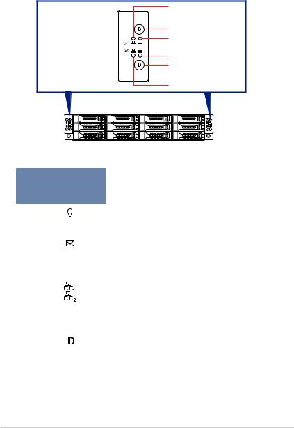
1.7LED information
1.7.1Front panel LEDs
Power button with LED 
 Message LED

Message LED  Power button with LED

1 2
1 2
LAN1 LED
Location button with LED LAN2 LED
LAN2 LED
Location button with LED
LAN1 LED
LED |
Icon |
Display |
Description |
||
status |
|||||
|
|
|
|
|
|
Power LED |
|
|
ON |
System power ON |
|
|
|
|
|
|
|
|
|
|
OFF |
System is normal; no incoming event |
|
Message LED |
|
|
|
|
|
|
|
ON |
A hardware monitor event is indicated |
||
|
|
|
|||
|
|
|
|
|
|
|
|
|
OFF |
No LAN connection |
|
|
|
|
|
|
|
LAN LEDs |
|
|
Blinking |
LAN is transmitting or receiving data |
|
|
|
|
|
|
|
|
|
|
ON |
LAN connection is present |
|
|
|
|
|
|
|
|
|
|
ON |
Location switched is pressed |
|
Location LED |
|
|
|
|
|
|
|
|
|
|
|
|
|
OFF |
Normal status. (Press the location switch again to turn off.) |
||
|
|
|
|||
|
|
|
|
|
|
1-12 |
Chapter 1: Product introduction |
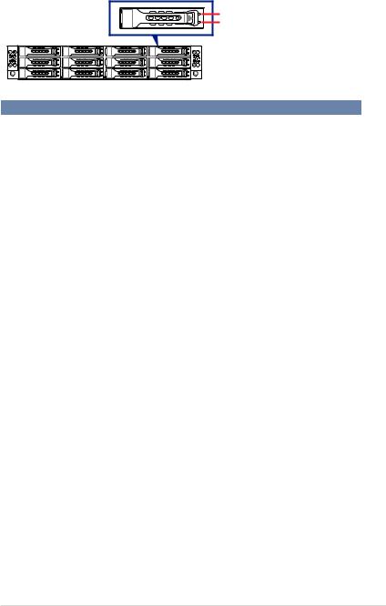
1.7.2HDD status LEDs
Active LED |
Status LED |
HDD LED |
|
|
Description |
|
|
OFF |
HDD not present |
||
HDD Activity LED (Green) |
ON |
HDD present, no activity |
||
|
|
|
||
Blinking |
1. |
Read/write data from/into the SATAII/SAS HDD |
||
|
||||
|
2. |
Locating (blinking with the HDD status LED) |
||
|
|
|||
|
OFF |
HDD not present |
||
|
|
|
||
HDD Status LED (Red) |
ON |
HDD has failed and should be swapped immediately |
||
|
|
|
||
|
Blinking |
1. |
RAID rebuilding |
|
|
2. |
Locating (blinking with the HDD activity LED) |
||
|
|
|||
RS720Q-E8-RS12 |
1-13 |

1-14 |
Chapter 1: Product introduction |
Hardware Information |
2 |
This chapter lists the hardware setup procedures that you have to perform when installing or removing system components.
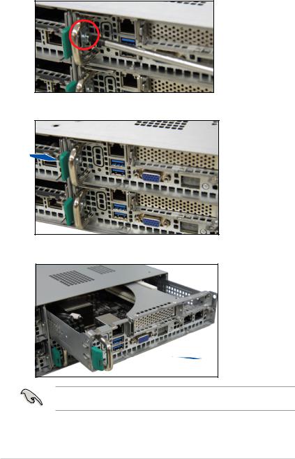
2.1Removing the server node
1.Remove the screw located on the node latch.
2.Hold the server node lever and press the green node latch.
3.Firmly pull the server node out of the server chassis.
When installing only two nodes, install the nodes to node slot number 1 and 3 or number 2 and 4. Refer to section 1.5 Rear panel features for details.
2-2 |
Chapter 2: Hardware information |
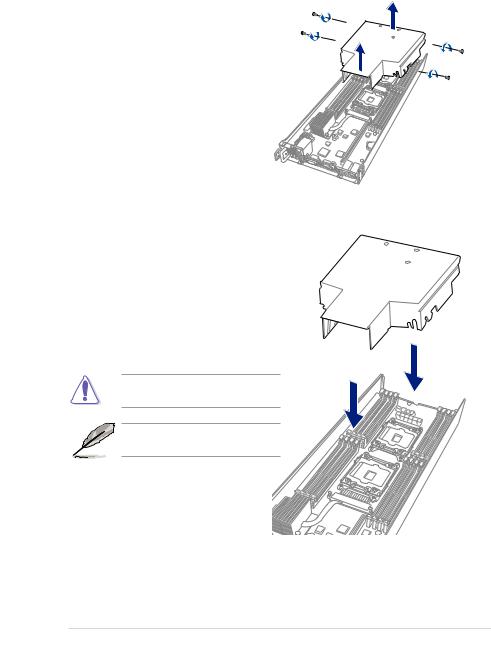
2.2Air Duct
The RS720Q-E8-RS12 server system comes with a motherboard fan air duct to enable better air flow inside the motherboard while the system is running.
Removing the air duct
1. Remove the screws securing the air duct in place
2. Carefully lift the air duct out of the chassis.
Installing the air duct
Position the air duct on top of the motherboard then carefully fit it on top of the motherboard.
Refer to the following illustration for the right orientation of the air duct.
Insert the air duct on the gaps between the memory slots.
Ensure that the air duct is firmly fitted to the motherboard.
RS720Q-E8-RS12 |
2-3 |
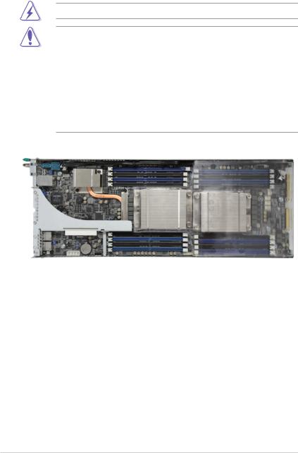
2.3Central Processing Unit (CPU)
The motherboard comes with a surface mount LGA 2011-3 Socket designed for the Intel® Xeon® Processor E5-2600 v3 product family processor.
Ensure that all power cables are unplugged before installing the CPU.
•Upon purchase of the motherboard, ensure that the PnP cap is on the socket and
the socket contacts are not bent. Contact your retailer immediately if the PnP cap is missing, or if you see any damage to the PnP cap/socket contacts/motherboard components. ASUS shoulders the repair cost only if the damage is shipment/transitrelated.
•Keep the cap after installing the motherboard. ASUS will process Return Merchandise Authorization (RMA) requests only if the motherboard comes with the cap on the LGA
2011-3 socket.
•The product warranty does not cover damage to the socket contacts resulting from incorrect CPU installation/removal, or misplacement/loss/incorrect removal of the PnP cap.
2-4 |
Chapter 2: Hardware information |
 Loading...