


 Loading...
RS700A-E9 Series
RS700A-E9-RS4
RS700A-E9-RS12
1U Rackmount Server
User Guide

E14044
Revised Edition V3
March 2018
Copyright © 2018 ASUSTeK COMPUTER INC. All Rights Reserved.
No part of this manual, including the products and software described in it, may be reproduced, transmitted, transcribed, stored in a retrieval system, or translated into any language in any form or by any means, except documentation kept by the purchaser for backup purposes, without the express written permission of ASUSTeK COMPUTER INC. (“ASUS”).
ASUS provides this manual “as is” without warranty of any kind, either express or implied, including but not limited to the implied warranties or conditions of merchantability or fitness for a particular purpose. In no event shall ASUS, its directors, officers, employees, or agents be liable for any indirect, special, incidental, or consequential damages (including damages for loss of profits, loss of business, loss of use or data, interruption of business and the like), even if ASUS has been advised of the possibility of such damages arising from any defect or error in this manual or product.
Specifications and information contained in this manual are furnished for informational use only, and are subject to change at any time without notice, and should not be construed as a commitment by ASUS. ASUS assumes no responsibility or liability for any errors or inaccuracies that may appear in this manual, including the products and software described in it.
Product warranty or service will not be extended if: (1) the product is repaired, modified or altered, unless such repair, modification of alteration is authorized in writing by ASUS; or (2) the serial number of the product is defaced or missing.
Products and corporate names appearing in this manual may or may not be registered trademarks or copyrights of their respective companies, and are used only for identification or explanation and to the owners’ benefit, without intent to infringe.
ii

Contents
Safety information..................................................................................................... |
vii |
About this guide.......................................................................................................... |
ix |
Chapter 1: Product Introduction
1.1 |
System package contents......................................................................... |
1-2 |
|
1.2 |
Serial number label..................................................................................... |
1-3 |
|
1.3 |
System specifications................................................................................ |
1-4 |
|
1.4 |
Front panel features................................................................................... |
1-7 |
|
1.5 |
Rear panel features.................................................................................... |
1-8 |
|
1.6 |
Internal features.......................................................................................... |
1-9 |
|
1.7 |
LED information........................................................................................ |
1-11 |
|
|
1.7.1 |
Front panel LEDs....................................................................... |
1-11 |
|
1.7.2 |
Storage device status LED........................................................ |
1-12 |
|
1.7.3 |
LAN (RJ-45) LEDs..................................................................... |
1-13 |
|
1.7.4 |
Rear panel LEDs....................................................................... |
1-13 |
|
1.7.5 |
Q-Code table............................................................................. |
1-14 |
Chapter 2: Hardware Information
2.1 |
Chassis cover............................................................................................. |
2-2 |
|
2.2 |
Central Processing Unit (CPU).................................................................. |
2-3 |
|
|
2.2.1 |
Installing the CPU and heatsink................................................... |
2-3 |
2.3 |
System memory.......................................................................................... |
2-7 |
|
|
2.3.1 |
Overview...................................................................................... |
2-7 |
|
2.3.2 |
Memory Configurations................................................................ |
2-8 |
|
2.3.3 |
Installing a DIMM on a single clip DIMM socket.......................... |
2-9 |
2.4 |
Storage devices........................................................................................ |
2-10 |
|
2.5 |
Expansion slot.......................................................................................... |
2-17 |
|
|
2.5.1 |
Installing an expansion card to the riser card bracket............... |
2-17 |
2.5.2Installing an expansion card to the butterfly riser
|
card bracket............................................................................... |
2-18 |
2.5.3 |
Installing an ASUS PIKE II card................................................. |
2-21 |
2.5.4Installing an ASUS PCIE-NVME2-OCuLink card to the
butterfly riser card bracket |
|
(optional for RS700A-E9-RS12 only)......................................... |
2-24 |
2.5.5Installing an ASUS PCIE-NVME4-OCuLink card to the
|
riser card bracket (optional for RS700A-E9-RS12 only)............ |
2-27 |
2.5.6 |
Configuring an expansion card.................................................. |
2-29 |
2.5.7 |
Installing Mezzanine cards........................................................ |
2-30 |
2.5.8 |
Installing M.2 (NGFF) cards....................................................... |
2-33 |
iii

Contents
2.6 |
Cable connections.................................................................................... |
2-35 |
2.7 |
Backplane cabling.................................................................................... |
2-36 |
2.8Storage device configuration and cabling
(for RS700A-E9-RS12 only)...................................................................... |
2-38 |
|
2.8.1 |
8 x SATA storage device configuration and cabling.................. |
2-39 |
2.8.2 |
10 x SATA storage device configuration and cabling................ |
2-42 |
2.8.38 x SATA/SAS and 4 x SATA storage device configuration
|
|
and cabling................................................................................ |
2-46 |
|
2.8.4 |
2 x NMVe storage device configuration and cabling................. |
2-51 |
|
2.8.5 |
4 x NMVe storage device configuration and cabling................. |
2-54 |
|
2.8.6 |
8 x NMVe storage device configuration and cabling................. |
2-59 |
2.9 |
Removable/optional components........................................................... |
2-65 |
|
|
2.9.1 |
System fans............................................................................... |
2-65 |
|
2.9.2 |
Redundant power supply module.............................................. |
2-66 |
|
2.9.3 |
Replacing optical drive (optional for RS700A-E9-RS4)............. |
2-67 |
Chapter 3: Installation Options
3.1 |
Tool-less Friction Rail Kit.......................................................................... |
3-2 |
3.2 |
Rail kit dimensions..................................................................................... |
3-4 |
Chapter 4: Motherboard Information
4.1 |
Motherboard layout |
....................................................................................4-2 |
4.2 |
Jumpers....................................................................................................... |
4-4 |
4.3 |
Internal LEDs............................................................................................... |
4-9 |
4.4 |
Internal connectors.................................................................................. |
4-12 |
Chapter 5: BIOS Setup
5.1 |
Managing and updating your BIOS........................................................... |
5-2 |
|
|
5.1.1 |
ASUS CrashFree BIOS 3 utility................................................... |
5-2 |
|
5.1.2 |
ASUS EZ Flash Utility.................................................................. |
5-3 |
|
5.1.3 |
BUPDATER utility........................................................................ |
5-4 |
5.2 |
BIOS setup program................................................................................... |
5-6 |
|
|
5.2.1 |
BIOS menu screen...................................................................... |
5-7 |
|
5.2.2 |
Menu bar...................................................................................... |
5-7 |
|
5.2.3 |
Menu items.................................................................................. |
5-8 |
|
5.2.4 |
Submenu items............................................................................ |
5-8 |
|
5.2.5 |
Navigation keys........................................................................... |
5-8 |
|
5.2.6 |
General help................................................................................ |
5-8 |
iv

Contents
|
5.2.7 |
Configuration fields...................................................................... |
5-8 |
|
5.2.8 |
Pop-up window............................................................................ |
5-8 |
|
5.2.9 |
Scroll bar...................................................................................... |
5-8 |
5.3 |
Main menu................................................................................................... |
5-9 |
|
|
5.3.1 |
System Date [Day xx/xx/xxxx]..................................................... |
5-9 |
|
5.3.2 |
System Time [xx:xx:xx]................................................................ |
5-9 |
5.4 |
Advanced menu........................................................................................ |
5-10 |
|
|
5.4.1 |
Trusted Computing.................................................................... |
5-11 |
|
5.4.2 |
PSP Firmware Versions............................................................. |
5-11 |
|
5.4.3 |
APM........................................................................................... |
5-12 |
|
5.4.4 |
Smart Settings........................................................................... |
5-13 |
|
5.4.5 |
NCT6793D Super IO Configuration........................................... |
5-13 |
|
5.4.6 |
Onboard LAN Configuration...................................................... |
5-14 |
|
5.4.7 |
Serial Port Console Redirection................................................. |
5-15 |
|
5.4.8 |
CPU Configuration..................................................................... |
5-17 |
|
5.4.9 |
PCI Subsystem Settings............................................................ |
5-18 |
|
5.4.10 |
Network Stack Configuration..................................................... |
5-19 |
|
5.4.11 |
CSM Configuration.................................................................... |
5-20 |
|
5.4.12 |
NVMe Configuration.................................................................. |
5-21 |
|
5.4.13 |
SATA Configuration................................................................... |
5-21 |
|
5.4.14 |
USB Configuration..................................................................... |
5-22 |
|
5.4.15 |
iSCSI Configuration................................................................... |
5-23 |
5.5 |
Chipset menu............................................................................................ |
5-24 |
|
5.6 |
Security menu........................................................................................... |
5-25 |
|
5.7 |
Boot menu................................................................................................. |
5-28 |
|
5.8 |
Tool menu.................................................................................................. |
5-29 |
|
5.9 |
Save & Exit menu...................................................................................... |
5-29 |
|
5.10 |
AMD CBS menu........................................................................................ |
5-31 |
|
|
5.10.1 |
Zen Common Options................................................................ |
5-31 |
|
5.10.2 |
DF Common Options................................................................. |
5-31 |
|
5.10.3 |
UMC Common Option............................................................... |
5-32 |
|
5.10.4 |
NBIO Common Options............................................................. |
5-32 |
5.11 |
Event Logs menu...................................................................................... |
5-33 |
|
|
5.11.1 Change Smbios Event Log Settings.......................................... |
5-33 |
|
|
5.11.2 View Smbios Event Log............................................................. |
5-33 |
|
5.12 |
Server Mgmt menu................................................................................... |
5-34 |
|
v

Contents
Chapter 6: Driver Installation
6.1 |
Management applications and utilities installation................................. |
6-2 |
6.2 |
Running the Support DVD......................................................................... |
6-2 |
6.3 |
AMD chipset device software installation................................................ |
6-5 |
6.4 |
Installing the Intel® I350-AM2 Gigabit Adapters driver............................ |
6-6 |
6.5 |
VGA driver installation............................................................................... |
6-8 |
Appendix
KNPP-D32 block diagram........................................................................................ |
A-2 |
Notices ..................................................................................................................... |
A-3 |
REACH ..................................................................................................... |
A-4 |
Australia statement notice............................................................................ |
A-4 |
ASUS contact information...................................................................................... |
A-5 |
vi
Safety information
Electrical Safety
•Before installing or removing signal cables, ensure that the power cables for the system unit and all attached devices are unplugged.
•To prevent electrical shock hazard, disconnect the power cable from the electrical outlet before relocating the system.
•When adding or removing any additional devices to or from the system, ensure that the power cables for the devices are unplugged before the signal cables are connected. If possible, disconnect all power cables from the existing system before you add a device.
•If the power supply is broken, do not try to fix it by yourself. Contact a qualified service technician or your dealer.
Operation Safety
•Any mechanical operation on this server must be conducted by certified or experienced engineers.
•Before operating the server, carefully read all the manuals included with the server package.
•Before using the server, ensure all cables are correctly connected and the power cables are not damaged. If any damage is detected, contact your dealer as soon as possible.
•To avoid short circuits, keep paper clips, screws, and staples away from connectors, slots, sockets and circuitry.
•Avoid dust, humidity, and temperature extremes. Place the server on a stable surface.
•If you encounter technical problems with the product, contact a qualified service technician or your retailer.
This product is equipped with a three-wire power cable and plug for the user’s safety. Use the power cable with a properly grounded electrical outlet to avoid electrical shock.
vii
Lithium-Ion Battery Warning
CAUTION! Danger of explosion if battery is incorrectly replaced. Replace only with the same or equivalent type recommended by the manufacturer. Dispose of used batteries according to the manufacturer’s instructions.
Heavy System
CAUTION! This server system is heavy. Ask for assistance when moving or carrying the system.
Optical Drive Safety Information
Laser Safety Information
CLASS 1 LASER PRODUCT
To prevent exposure to the optical drive’s laser, do not attempt to disassemble or repair the optical drive by yourself. For your safety, contact a professional technician for assistance.
viii

About this guide
Audience
This user guide is intended for system integrators, and experienced users with at least basic knowledge of configuring a server.
Contents
This guide contains the following parts:
1.Chapter 1: Product Introduction
This chapter describes the general features of the server, including sections on front panel and rear panel specifications.
2.Chapter 2: Hardware Information
This chapter lists the hardware setup procedures that you have to perform when installing or removing system components.
3.Chapter 3: Installation Options
This chapter describes how to install optional components into the barebone server.
4.Chapter 4: Motherboard Information
This chapter gives information about the motherboard that comes with the server. This chapter includes the motherboard layout, jumper settings, and connector locations.
5.Chapter 5: BIOS Setup
This chapter tells how to change system settings through the BIOS Setup menus and describes the BIOS parameters.
6.Chapter 6: Driver Installation
This chapter provides instructions for installing the necessary drivers for different system components.
ix
Conventions
To ensure that you perform certain tasks properly, take note of the following symbols used throughout this manual.
DANGER/WARNING: Information to prevent injury to yourself when trying to complete a task.
CAUTION: Information to prevent damage to the components when trying to complete a task.
IMPORTANT: Instructions that you MUST follow to complete a task.
NOTE: Tips and additional information to help you complete a task.
Typography
Bold text |
Indicates a menu or an item to select. |
Italics |
Used to emphasize a word or a phrase. |
<Key> |
Keys enclosed in the less-than and greater-than |
sign means that you must press the enclosed key. |
|
|
Example: <Enter> means that you must press |
|
the Enter or Return key. |
<Key1>+<Key2>+<Key3> |
If you must press two or more keys simultaneously, |
the key names are linked with a plus sign (+). |
|
|
Example: <Ctrl>+<Alt>+<Del> |
Command |
Means that you must type the command |
|
exactly as shown, then supply the required |
|
item or value enclosed in brackets. |
Example: At the DOS prompt, type the command line: format A:/S
References
Refer to the following sources for additional information, and for product and software updates.
1.ASUS Control Center (ACC) user guide
This manual tells how to set up and use the proprietary ASUS server management utility. Visit asuscontrolcenter.asus.com for more information.
2.ASUS websites
The ASUS websites worldwide provide updated information for all ASUS hardware and software products. Refer to the ASUS contact information.
x
Product Introduction |
1 |
This chapter describes the general features of the chassis kit. It includes sections on front panel and rear panel specifications.
1.1System package contents
Check your system package for the following items.
Model Name |
RS700A-E9-RS4 |
RS700A-E9-RS12 |
Chassis |
ASUS R12F 1U Rackmount Chassis |
ASUS R12F 1U Rackmount Chassis |
Motherboard |
ASUS KNPP-D32 Server Board |
ASUS KNPP-D32 Server Board |
|
1 x 800W 80PLUS Platinum Power Supply |
1 x 800W 80PLUS Platinum Power Supply |
|
1 x 3.5-inch Storage Device Backplane |
1 x 2.5-inch Storage Device Backplane |
|
4 x 3.5-inch Storage Device Trays or |
12 x 2.5-inch Storage Device Trays or |
|
Dummy Trays |
Dummy Trays |
Component |
1 x Front Panel Board |
1 x Front Panel Board |
|
2 x Riser Card |
2 x Riser Card |
|
8 x System Fans (40 mm x 40 mm x 56 |
8 x System Fans (40 mm x 40 mm x 56 |
|
mm) |
mm) |
|
|
1 x PCIE-NVME2-OCuLink card |
|
1 x AMD EPYC™ Support DVD |
1 x AMD EPYC™ Support DVD |
Accessories |
1 x Bag of Screws |
1 x Bag of Screws |
2 x CPU Heatsink |
2 x CPU Heatsink |
|
|
2 x AC Power Cable |
2 x AC Power Cable |
|
1 x Redundant 800W 80PLUS Platinum |
1 x Redundant 800W 80PLUS Platinum |
|
Power Supply (Second PSU) |
Power Supply (Second PSU) |
|
1 x Friction Rail Kit |
1 x Friction Rail Kit |
Optional |
1 x Slim type DVD-RW |
2 x OCuLink to OCuLink cables for NVMe |
Items |
|
1 x PCIE-NVME2-OCuLink card with two |
|
|
cables |
|
|
1 x PCIE-NVME4-OCuLink card with four |
|
|
cables |
If any of the above items is damaged or missing, contact your retailer.
1-2 |
Chapter 1: Product Introduction |

1.2Serial number label
The product’s serial number contains 12 characters such as xxS0xxxxxxxx and printed on the sticker at the server's front cover.
The correct serial number of the product is required if you need to request for support from the ASUS Technical Support team.
RS700A-E9-RS4
xxS0xxxxxxxx
RS700A-E9-RS12
xxS0xxxxxxxx
ASUS RS700A-E9 Series |
1-3 |

1.3System specifications
The ASUS RS700A-E9 Series features the ASUS KNPP-D32 server board. The server supports AMD EPYC™ 7000 Series processors plus other latest technologies through the chipsets onboard.
Model Name |
|
RS700A-E9-RS4 |
RS700A-E9-RS12 |
|
|
|
|
|
|
Motherboard |
|
KNPP-D32 |
|
|
Processor Support |
AMD EPYC™ 7000 Series |
|
||
xGMI (External Global Memory Interface Link) |
||||
|
|
|||
Core Logic |
|
Integrated I/O – No chipset |
|
|
|
|
|
||
|
Total Slots |
32 (8-channel per CPU, 16 DIMM per CPU) |
||
|
Capacity |
Maximum up to 4096GB |
|
|
Memory |
Memory Type |
DDR4 2666 / 2400 / 2133 RDIMM/ LRDIMM |
||
* Refer to ASUS server AVL for the latest update |
||||
|
||||
|
|
|||
|
|
|
|
|
|
|
8GB, 16GB, 32GB (RDIMM) |
|
|
|
Memory Size |
32GB, 64GB, 128GB (LRDIMM) |
|
|
|
|
* Refer to ASUS server AVL for the latest update |
||
|
|
|
|
|
|
Total PCI/PCI-E/ |
3+1 |
|
|
|
PIKE Slots |
|
||
|
|
|
||
|
|
|
|
|
|
|
1 x PCI-E x16 (Gen3 x16 link), |
1 x PCI-E x16 (Gen3 x16 |
|
|
|
FH, HL |
link), FH, HL (For Optional |
|
|
|
1 x PCI-E x16 (Gen3 x8 link), |
NVME4-OCuLink Card) |
|
Expansion |
|
|
||
|
LP |
1 x PCI-E x16 (Gen3 x8 link), |
||
Slots |
Slot Type |
1 x PCI-E x8 (Gen3 x8 link), LP |
LP |
|
|
1 x PCI-E x8 (Gen3 x8 |
|||
|
|
1 x OCP 2.0 Mezzanine (Gen3 |
||
|
|
link), LP (For Optional |
||
|
|
x16 link) |
||
|
|
NVME2-OCuLink Card) |
||
|
|
|
||
|
|
|
1 x OCP 2.0 Mezzanine (Gen3 |
|
|
|
|
x16 link) |
|
|
SATA Controller |
10 x SATA 6Gb/s ports |
|
|
|
|
2 x M.2 connectors (SATA 6Gb/s & PCI-E Gen3 x4 link) |
||
Disk |
|
Optional: |
|
|
Controller |
SAS Controller |
ASUS PIKE II 3008 8-port SAS HBA card |
||
|
||||
|
ASUS PIKE II 3108 8-port SAS HW RAID card |
|||
|
|
|||
|
|
12G SAS Support |
|
|
|
|
4 x 2.5” or 3.5” Hot-swap |
12 x 2.5” Hot-swap Storage |
|
|
I = internal |
Storage Bays |
Bays (up to 4 x NVMe/ |
|
Storage |
2 x M.2 2242/2260/2280/22110 |
SATA + 4 x NVMe/SAS/ |
||
A or S will be |
||||
Bays |
SATA + 4 x SAS/SATA) |
|||
hot-swappable |
(supports SATA/PCIE M.2) |
|||
|
2 x M.2 2242/2260/2280/22110 |
|||
|
|
|
||
|
|
|
(supports SATA/PCIE M.2) |
|
|
|
(continued on the next page) |
|
|
1-4 |
Chapter 1: Product Introduction |

Model Name |
|
RS700A-E9-RS4 |
RS700A-E9-RS12 |
|
|
|
|
|
|
Networking |
LAN |
1 x Dual Port Intel I350-AM2 Gigabit LAN controller |
||
1 x Management Port |
|
|||
|
|
|
||
Graphic |
VGA |
Aspeed AST2500 64MB |
|
|
Auxiliary Storage Device Bay |
Optional: |
N/A |
||
(Floppy / Optical Drive) |
1 x Slim type Optical Drive Bay |
|
||
|
|
Front I/O Ports: |
Rear I/O Ports: |
|
|
|
2 x USB 3.0 ports |
2 x USB 3.0 ports |
|
|
|
1 x VGA port |
1 x VGA port |
|
|
|
Rear I/O Ports: |
2 x RJ-45 GbE LAN ports |
|
|
|
2 x USB 3.0 ports |
1 x RJ-45 Mgmt LAN port |
|
|
|
1 x VGA port |
Rear Switch/LED: |
|
|
|
2 x RJ-45 GbE LAN ports |
1 x Power switch |
|
|
|
1 x RJ-45 Mgmt LAN port |
1 x Q-Code/Port 80 LED |
|
|
|
Rear Switch/LED: |
1 x Message LED |
|
I/O ports, Switches, and |
1 x Power switch |
1 x Storage device LED |
||
1 x Q-Code/Port 80 LED |
1 x Location LED |
|||
LEDs |
|
|||
|
1 x Message LED |
Front Switch/LED: |
||
|
|
|||
|
|
1 x Storage device LED |
1 x Power switch/LED |
|
|
|
1 x Location LED |
1 x Location LED |
|
|
|
Front Switch/LED: |
1 x Message LED |
|
|
|
1 x Power switch/LED |
1 x Storage device LED |
|
|
|
1 x Location switch/LED |
LAN 1-2 LED |
|
|
|
1 x Message LED |
|
|
|
|
1 x Storage device LED |
|
|
|
|
LAN 1-4 LEDs |
|
|
|
|
* LAN 3-4 for Mezzanine card use |
|
|
|
|
|
|
|
|
Out of Band |
|
|
|
Management |
Remote |
On-Board ASMB9-iKVM for KVM-over-IP |
||
Hardware |
|
|
||
Solution |
|
|
|
|
|
Software |
ASUS Control Center (Classic) |
|
|
|
|
Windows® Server 2012 R2 |
|
|
|
|
Windows® Server 2016 |
|
|
|
|
RedHat® Enterprise Linux |
|
|
|
|
SuSE® Linux Enterprise Server |
|
|
OS Support |
|
CentOS |
|
|
|
|
Ubuntu |
|
|
|
|
VMware |
|
|
|
|
Citrix XenServer |
|
|
|
|
* Refer to http://www.asus.com for the latest OS support. |
||
|
|
(continued on the next page) |
|
|
ASUS RS700A-E9 Series |
1-5 |

Model Name |
RS700A-E9-RS4 |
RS700A-E9-RS12 |
|
|
|
Regulatory Compliance |
BSMI, CE, FCC (Class A) |
|
|
|
|
Dimension (Depth x Width x |
686 mm x 444 mm x 44 mm (1U) |
|
Height) |
27” x 17.48” x 1.73” |
|
Net Weight Kg (CPU, DRAM |
|
|
& storage device not |
11.05 Kg |
11.35 Kg |
included) |
|
|
|
|
|
Gross Weight Kg (CPU, |
|
|
DRAM & storage device not |
12.6 Kg |
12.9 Kg |
included, packing included) |
|
|
|
|
|
Power Supply |
1+1 Redundant 800W 80 PLUS Platinum Power Supply |
|
(different configuration |
Rating: 100-127Vac/200-240Vac, 9.4A/4.72A (x2), 50/60Hz Class I |
|
by region) |
or 240Vdc, 4.6A (240Vdc only for China) |
|
|
Operating temperature: 10°C ~ 35°C |
|
Environment |
Non operating temperature: -40°C ~ 60°C |
|
|
Non operating humidity: 20% ~ 90% (Non condensing) |
|
*Specifications are subject to change without notice.
1-6 |
Chapter 1: Product Introduction |
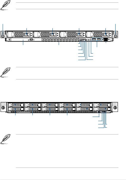
1.4Front panel features
The barebone server displays a simple yet stylish front panel with easily accessible features. The power and reset buttons, LED indicators, slim type optical drive (optional on RS700A- E9-RS4 only), two USB ports (on RS700A-E9-RS4 only), and VGA port (on RS700A-E9-RS4 only) are located on the front panel.
Refer to section 1.7 LED information for the LED descriptions.
RS700A-E9-RS4
Rack screw |
|
|
|
|
Rack screw |
Bay 1 |
Bay 2 |
Bay 3 |
|
Bay 4 |
|
|
|
4 |
3 |
2 |
1 |
|
|
LAN 4 LED |
|
|
VGA port |
Optical drive (optional) |
Asset tag |
LAN 3 LED |
|
|
|
|
|
USB ports |
|||
|
|
LAN 2 LED |
|
|
|
|
|
|
|
|
|
|
|
LAN 1 LED |
|
|
Reset button |
|
|
Message LED |
|
|
Location button |
|
Storage device LED |
|
|
Power button |
|
• All bays support SATA by default. SAS support requires optional ASUS PIKE II card.
• All bays support 3.5” and 2.5” drives with trays.
RS700A-E9-RS12
Rack screw |
|
|
|
|
|
|
|
|
|
|
|
Bay 10 |
|
|
|
Bay 12 |
||||||
|
|
|
Bay 1 |
|
Bay 3 |
|
Bay 5 |
|
Bay 7 |
Bay 9 |
|
Bay 11 |
Rack screw |
|||||||||
|
|
|
|
|
|
|
|
|
|
|
|
|
|
|
|
|
|
|
|
|
|
|
|
|
|
|
|
|
|
|
|
|
|
|
|
|
|
|
|
|
|
|
|
|
|
|
|
|
|
|
|
|
|
|
|
|
|
|
|
|
|
|
|
|
|
|
|
|
|
|
|
|
|
|
|
|
|
|
|
|
|
|
|
|
|
|
|
|
|
|
|
|
|
|
|
|
|
|
|
|
|
|
|
|
|
|
|
|
|
|
|
|
|
|
|
|
|
|
|
|
|
|
|
|
|
|
|
|
|
|
|
|
|
|
|
|
|
|
|
|
|
|
|
|
|
|
|
|
|
|
|
|
|
|
|
|
|
|
|
|
|
|
|
|
|
|
Bay 2 |
Bay 4 |
Bay 6 |
Bay 8 |
||
|
|
|
|
|
|
Asset tag
Power button |
|
Power LED |
|
Message LED |
LAN 1 LED |
Location LED |
LAN 2 LED |
•Bay 1 to bay 4 supports SATA by default. SAS support requires optional ASUS PIKE II card.
•Bay 5 to bay 8 supports SATA by default. SAS support requires optional ASUS PIKE II card. NVMe support requires optional upgrade kit.
•Bay 9 to bay 12 supports SATA with optional cables. NVMe support requires optional upgrade kit.
•All bays support 2.5” drives with trays.
ASUS RS700A-E9 Series |
1-7 |

1.5Rear panel features
The rear panel includes the expansion slots, system power sockets, and rear fans. The middle part includes the I/O shield with openings for the rear panel connectors on the motherboard.
|
|
Expansion slots |
|
|
Expansion slot |
|||||||||
|
|
|
|
|
|
|
|
|
|
|
|
|
|
|
|
|
|
|
|
|
|
|
|
|
|
|
|
|
|
|
|
|
|
|
|
|
|
|
|
|
|
|
|
|
|
|
|
|
|
|
|
|
|
|
|
|
|
|
|
|
|
|
|
|
|
|
|
|
|
|
|
|
|
|
|
|
|
|
|
|
|
|
|
|
|
|
|
|
|
Redundant Power supply and Power cord connector
USB ports VGA port
Power button
Q-Code LED
Management LAN port 1*
LAN port 1
LAN port 2
Storage device LED Message LED Location LED
*This port is for ASUS ASMB9-iKVM only.
1-8 |
Chapter 1: Product Introduction |

1.6Internal features
The barebone server includes the basic components as shown.
RS700A-E9-RS4
1. Redundant Power supply
2. ASUS KNPP-D32 Server
Board
3. System fans
4. 4 x 3.5“ storage device trays
5. SATA/SAS backplane (hidden)
6. Slim type optical drive (hidden)
7. OCP Mezzanine card (optional)
8. Butterfly riser card
(2 x Gen3 x8 link)
9. Riser card (Gen3 x16 link)
10. Asset tag (hidden)
The barebone server does not include a floppy disk drive. Connect a USB floppy disk drive to any of the USB ports on the front or rear panel if you need to use a floppy disk.
A protection film is pre-attached to the front cover before shipping. Please remove the protection film before turning on the system for proper heat dissipation.
WARNING
HAZARDOUS MOVING PARTS
KEEP FINGERS AND OTHER BODY PARTS AWAY
ASUS RS700A-E9 Series |
1-9 |
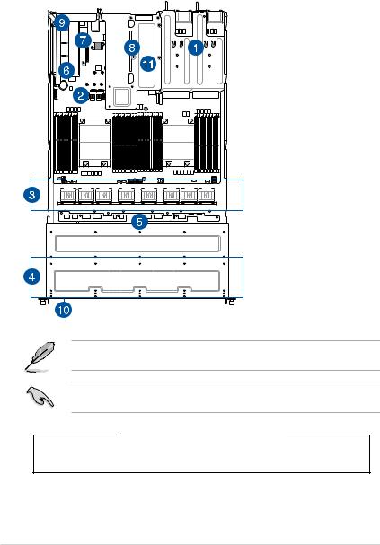
RS700A-E9-RS12
1. Redundant Power supply
2. ASUS KNPP-D32 Server
Board
3. System fans
4. 12 x 2.5” storage device trays
5. SATA/SAS/NVMe
backplane (hidden)
6. PCIE-NVME4-OCuLink
card (optional)
7. OCP Mezzanine card (optional)
8. Butterfly riser card
(2 x Gen3 x8 link)
9. Riser card (Gen3 x16 link)
10. Asset tag (hidden)
11. PCIE-NVME2-OCuLink card (hidden, optional on x8 slot (Gen3 x8 link) on butterfly riser card)
The barebone server does not include a floppy disk drive. Connect a USB floppy disk drive to any of the USB ports on the front or rear panel if you need to use a floppy disk.
A protection film is pre-attached to the front cover before shipping. Please remove the protection film before turning on the system for proper heat dissipation.
WARNING
HAZARDOUS MOVING PARTS
KEEP FINGERS AND OTHER BODY PARTS AWAY
1-10 |
Chapter 1: Product Introduction |
1.7LED information
1.7.1Front panel LEDs
RS700A-E9-RS4
4 |
3 |
2 |
1 |
LAN 4 LED 
LAN 3 LED
LAN 2 LED
LAN 1 LED
Location button with LED Power button with LED Storage device LED Message LED
RS700A-E9-RS12
2 |
1 |
Power button |
|
|
|
|
|
|
|
|
|
|
|
|
|
|
|
||
Power LED |
|
|
|
|
|
|
||
|
|
|
|
|
|
|||
Message LED |
|
|
|
|
|
LAN 1 LED |
||
|
|
|||||||
Location LED |
|
|
|
|
|
LAN 2 LED |
||
|
|
|
|
|
||||
LED |
Icon Display status |
Description |
|
Power LED |
ON |
System power ON |
|
|
|
|
|
|
OFF |
No activity |
|
Storage Device |
Blinking |
Read/write data into the storage device |
|
Access LED |
|
(Does not support storage devices |
|
|
|
connected to the onboard SATA) |
|
Message LED |
OFF |
System is normal; no incoming event |
|
ON |
A hardware monitor event is indicated |
||
|
|||
|
OFF |
Normal status |
|
Location LED |
ON |
Location switch is pressed |
|
|
|
(Press the location switch again to turn off) |
OFF LAN LEDs Blinking
ON
No LAN connection
LAN is transmitting or receiving data LAN connection is present
ASUS RS700A-E9 Series |
1-11 |
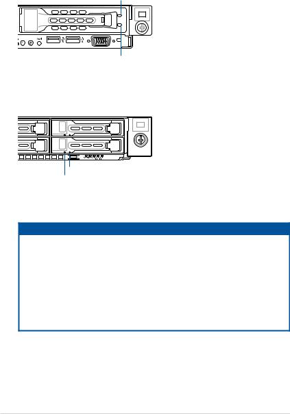
1.7.2Storage device status LED
RS700A-E9-RS4
Red LED
Green LED
RS700A-E9-RS12
2 1
Green LED
Red LED
SATA/SAS Storage Device LED Description
GREEN |
ON |
SATA/SAS storage device power ON |
|
RED |
ON |
Storage device has failed and should be swapped immediately |
|
GREEN/ |
Blinking |
RAID rebuilding |
|
RED |
|||
|
|
||
GREEN/ |
Blinking |
Locate |
|
RED |
|||
|
|
||
GREEN/ |
OFF |
Storage device not found |
|
RED |
|||
|
|
||
GREEN |
Blinking |
Read/write data from/into the SATA/SAS storage device |
1-12 |
Chapter 1: Product Introduction |
1.7.3LAN (RJ-45) LEDs
ACT/LINK LED SPEED LED
|
|
|
|
|
|
|
|
|
|
|
|
|
|
|
|
|
|
|
|
|
|
|
|
|
|
|
|
|
|
|
|
|
|
|
|
|
|
|
|
|
|
|
|
|
|
|
|
|
|
|
|
|
|
ACT/LINK LED |
|
|
SPEED LED |
||
Status |
Description |
|
Status |
Description |
|||||||
|
|||||||||||
|
OFF |
No link |
|
OFF |
10 Mbps connection |
||||||
GREEN |
Linked |
|
ORANGE |
100 Mbps connection |
|||||||
BLINKING |
Data activity |
|
GREEN |
1 Gbps connection |
|||||||
1.7.4Rear panel LEDs
|
|
|
|
|
|
|
|
|
|
|
|
|
|
|
|
|
|
|
|
|
|
|
|
|
|
|
|
|
|
|
|
|
|
|
|
|
|
|
|
|
|
|
|
|
|
|
|
|
|
|
|
|
|
|
|
|
|
|
|
|
|
|
|
|
|
|
|
|
|
|
|
|
|
|
|
|
|
|
|
|
|
|
|
|
|
|
|
|
|
|
|
|
|
|
|
|
|
|
Storage device LED |
||||
|
|
|
|
|
|
|
|
|
|
|
|
|
|
|
|
|
|
|
|
|
|||||
Q-Code LED |
|
|
|
|
|
|
|
|
|
|
|
|
|
|
Message LED |
||||||||||
|
|
|
|
|
|
|
|
|
|
|
|
|
|
||||||||||||
|
|
|
|
|
|
|
|
|
|
|
|
|
|
|
|
|
|
|
|
|
Location LED |
||||
|
|
|
|
|
|
|
|
|
|
|
|
|
|
|
|
|
|
|
|
||||||
|
|
|
|
|
|
|
|
|
|
|
|
|
|
|
|
|
|
|
|
|
|
|
|
||
LED |
Display status |
Description |
|||||||||||||||||||||||
|
|
|
|
|
|
|
|
|
|
|
|
OFF |
No activity |
||||||||||||
Storage device |
|
|
|
Blinking |
Read/write data into the storage device |
||||||||||||||||||||
Access LED |
|
|
|
|
|
|
|
|
|
|
|
|
(Does not support storage devices |
||||||||||||
|
|
|
|
|
|
|
|
|
|
|
|
|
|
|
|
|
|
|
connected to the onboard SATA) |
||||||
Message LED |
|
|
|
|
|
OFF |
System is normal; no incoming event |
||||||||||||||||||
|
|
|
|
|
ON |
A hardware monitor event is indicated |
|||||||||||||||||||
|
|
|
|
|
|
|
|
|
|
|
|
||||||||||||||
|
|
|
|
|
|
|
|
|
|
|
|
OFF |
Normal status |
||||||||||||
Location LED |
|
|
|
|
|
ON |
Location switch is pressed |
||||||||||||||||||
|
|
|
|
|
|
|
|
|
|
|
|
|
|
|
|
|
|
|
(Press the location switch again to turn off) |
||||||
ASUS RS700A-E9 Series |
1-13 |

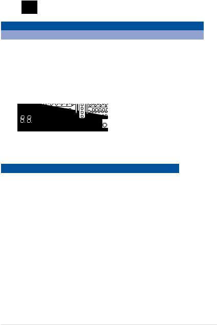
1.7.5Q-Code table
Action |
PHASE |
POST CODE |
TYPE |
DESCRIPTION |
|
|
|
0x01 |
Progress |
First post code |
|
|
|
0x02 |
Progress |
Load BSP microcode |
|
SEC Start up |
Security Phase |
0x03 |
Progress |
Perform early platform Initialization |
|
0x04 |
Progress |
Set cache as ram for PEI phase |
|||
|
|
||||
|
|
0x05 |
Progress |
Establish Stack |
|
|
|
0x06 |
Progress |
CPU Early Initialization |
|
|
|
0x00 |
Error |
General - Success |
|
|
|
0x01 |
Error |
Generic Error Code |
|
|
|
0x02 |
Error |
Generic Memory Error |
|
|
|
0x03 |
Error |
Buffer Overflow |
|
|
|
0x04 |
Error |
Invalid Parameter(s) |
|
|
|
0x05 |
Error |
Invalid Data Length |
|
|
|
0x06 |
Error |
Data Alignment Error |
|
|
|
0x07 |
Error |
Null Pointer Error |
|
|
|
0x08 |
Error |
Unsupported Function |
|
|
|
0x09 |
Error |
Invalid Service ID |
|
|
|
0x0A |
Error |
Invalid Address |
|
|
|
0x0B |
Error |
Out of Resource Error |
|
|
|
0x0C |
Error |
Timeout |
|
|
|
0x0D |
Error |
data abort exception |
|
|
|
0x0E |
Error |
prefetch abort exception |
|
|
|
0x0F |
Error |
Out of Boundary Condition Reached |
|
|
|
0x10 |
Error |
Data corruption |
|
|
|
0x11 |
Error |
Invalid command |
|
|
|
0x12 |
Error |
The package type provided by BR is incorrect |
|
|
|
0x13 |
Error |
Failed to retrieve FW header during FW validation |
|
|
|
0x14 |
Error |
Key size not supported |
|
|
|
0x15 |
Error |
Agesa0 verification error |
|
|
|
0x16 |
Error |
SMU FW verification error |
|
|
|
0x17 |
Error |
OEM SINGING KEY verification error |
|
|
|
0x18 |
Error |
Generic FW Validation error |
|
|
|
0x19 |
Error |
RSA operation fail - bootloader |
|
|
|
0x1A |
Error |
CCP Passthrough operation failed - internal status |
|
|
PSP Boot Loader |
0x1B |
Error |
AES operation fail |
|
PSP Boot |
phase (Error Post |
0x1C |
Error |
CCP state save failed |
|
|
Codes) |
0x1D |
Error |
CCP state restore failed |
|
|
|
0x1E |
Error |
SHA256 operation fail - internal status |
|
|
|
0x1F |
Error |
ZLib Decompression operation fail |
|
|
|
0x20 |
Error |
HMAC-SHA256 operation fail - internal status |
|
|
|
0x21 |
Error |
Booted from boot source not recognized by PSP |
|
|
|
0x22 |
Error |
PSP directory entry not found |
|
|
|
0x23 |
Error |
PSP failed to set the write enable latch |
|
|
|
0x24 |
Error |
PSP timed out because spirom took too long |
|
|
|
0x25 |
Error |
Cannot find BIOS directory |
|
|
|
0x26 |
Error |
SpiRom is not valid |
|
|
|
0x27 |
Error |
slave die has different security state from master |
|
|
|
0x28 |
Error |
SMI interface init failure |
|
|
|
0x29 |
Error |
SMI interface generic error |
|
|
|
0x2A |
Error |
invalid die ID executes MCM related function |
|
|
|
0x2B |
Error |
invalid MCM configuration table read from bootrom |
|
|
|
0x2C |
Error |
Valid boot mode wasn't detected |
|
|
|
0x2D |
Error |
NVStorage init failure |
|
|
|
0x2E |
Error |
NVStorage generic error |
|
|
|
0x2F |
Error |
MCM 'error' to indicate slave has more data to send |
|
|
|
0x30 |
Error |
MCM error if data size exceeds 32B |
|
|
|
0x31 |
Error |
Invalid client id for SVC MCM call |
|
|
|
0x32 |
Error |
MCM slave status register contains bad bits |
|
|
|
0x33 |
Error |
MCM call was made in a single die environment |
|
|
|
0x34 |
Error |
PSP secure mapped to invalid segment (should be 0x400_0000) |
|
|
|
0x35 |
Error |
No physical x86 cores were found on die |
|
|
|
0x36 |
Error |
Insufficient space for secure OS (range of free SRAM to SVC stack base) |
|
|
|
0x37 |
Error |
SYSHUB mapping memory target type is not supported |
|
|
|
0x38 |
Error |
Attempt to unmap permanently mapped TLB to PSP secure region |
(continued on the next page)
1-14 |
Chapter 1: Product Introduction |

Action |
PHASE |
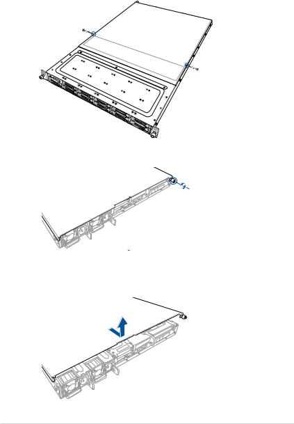
POST CODE |
TYPE |
DESCRIPTION |
|
|
0x39 |
Error |
Unable to map an SMN address to AXI space |
|
|
0x3A |
Error |
Unable to map a SYSHUB address to AXI space |
|
|
0x3B |
Error |
The count of CCXs or cores provided by bootrom is not consistent |
|
|
0x3C |
Error |
Uncompressed image size doesn't match value in compressed header |
|
|
0x3D |
Error |
Compressed option used in case where not supported |
|
|
0x3E |
Error |
Fuse info on all dies don't match |
|
|
0x3F |
Error |
PSP sent message to SMU; SMU reported an error |
|
|
0x40 |
Error |
Function RunPostX86ReleaseUnitTests failed in memcmp() |
|
|
0x41 |
Error |
Interface between PSP to SMU not available. |
|
|
0x42 |
Error |
Timer wait parameter too large |
|
|
0x43 |
Error |
Test harness module reported an error |
|
|
0x44 |
Error |
x86 wrote C2PMSG_0 interrupting PSP |
|
|
0x45 |
Error |
A write to an L3 register failed |
|
|
0x46 |
Error |
Mini-BL |
|
|
0x47 |
Error |
Mini-BL CCP HMAC Unit-test failed |
|
|
0x48 |
Error |
Potential stack corruption in jump to Mini BL |
|
|
0x49 |
Error |
Error in Validate and Loading AGESA APOB SVC call |
|
|
0x4A |
Error |
Correct fuse bits for DIAG_BL loading not set |
|
|
0x4B |
Error |
The UmcProgramKeys() function was not called by AGESA |
|
|
0x4C |
Error |
Secure unlock error |
|
|
0x4D |
Error |
Syshub register programming mismatch during readback |
|
|
0x4E |
Error |
Family ID in MP0_SFUSE_SEC[7:3] not correct |
|
|
0x4F |
Error |
An operation was invoked that can only be performed by the GM |
|
|
0x50 |
Error |
Failed to acquire host controller semaphore to claim ownership of SMB |
|
|
0x51 |
Error |
Timed out waiting for host to complete pending transactions |
|
|
0x52 |
Error |
Timed out waiting for slave to complete pending transactions |
|
|
0x53 |
Error |
Unable to kill current transaction on host |
|
|
0x54 |
Error |
One of: Illegal command |
|
|
0x55 |
Error |
An SMBus transaction collision detected |
|
|
0x56 |
Error |
Transaction failed to be started or processed by host |
|
|
0x57 |
Error |
An unsolicited SMBus interrupt was received |
|
PSP Boot Loader |
0x58 |
Error |
An attempt to send an unsupported PSP-SMU message was made |
PSP Boot |
phase (Error Post |
0x59 |
Error |
An error/data corruption detected on response from SMU for sent msg |
|
Codes) |
|||
|
0x5A |
Error |
MCM Steady-state unit test failed |
|
|
|
|||
|
|
0x5B |
Error |
S3 Enter failed |
|
|
0x5C |
Error |
AGESA BL did not set PSP SMU reserved addresses via SVC call |
|
|
0x5E |
Error |
CcxSecBisiEn not set in fuse RAM |
|
|
0x5F |
Error |
Received an unexpected result |
|
|
0x60 |
Error |
VMG Storage Init failed |
|
|
0x61 |
Error |
Failure in mbedTLS user app |
|
|
0x62 |
Error |
An error occured whilst attempting to SMN map a fuse register |
|
|
0x63 |
Error |
Fuse burn sequence/operation failed due to internal SOC error |
|
|
0x64 |
Error |
Fuse sense operation timed out |
|
|
0x65 |
Error |
Fuse burn sequence/operation timed out waiting for burn done |
|
|
0x66 |
Error |
Failure status indicating that the given SecureOS has been |
|
|
0x67 |
Error |
This PSP FW was revoked |
|
|
0x68 |
Error |
The platform model/vendor id fuse is not matching the BIOS public key |
|
|
token |
||
|
|
|
|
|
|
|
0x69 |
Error |
The BIOS OEM public key of the BIOS was revoked for this platform |
|
|
0x6A |
Error |
PSP level 2 directory not match expected value. |
|
|
0x6B |
Error |
BIOS level 2 directory not match expected value. |
|
|
0x6C |
Error |
HVB validation failure for BIOS RTM volume (OEM public/signature failed |
|
|
to validate). |
||
|
|
|
|
|
|
|
0x6D |
Error |
Generic error indicating the CCP HAL initialization failed |
|
|
0x94 |
Error |
Knoll failed to idle correctly after being reset |
|
|
0x95 |
Error |
Bad status returned by I2CKnollCheck |
|
|
0x96 |
Error |
NACK to general call (no device on Knoll I2C bus) |
|
|
0x97 |
Error |
Null pointer passed to I2CKnollCheck |
|
|
0x98 |
Error |
Invalid device-ID found during Knoll authentication |
|
|
0x99 |
Error |
Error during Knoll/Prom key derivation |
|
|
0x9A |
Error |
Null pointer passed to Crypto function |
|
|
0x9B |
Error |
Error in checksum from wrapped Knoll/Prom keys |
|
|
0x9C |
Error |
Knoll returned an invalid response to a command |
|
|
0x9D |
Error |
Bootloader failed in Knoll Send Command function |
|
|
0x9E |
Error |
No Knoll device found by verifying MAC |
(continued on the next page)
ASUS RS700A-E9 Series |
1-15 |

Action |
PHASE |
POST CODE |
TYPE |
DESCRIPTION |
|
|
0xA0 |
Progress |
Bootloader successfully entered C Main |
|
|
0xA1 |
Progress |
Master initialized C2P / slave waited for master to init C2P |
|
|
0xA2 |
Progress |
HMAC key successfully derived |
|
|
0xA3 |
Progress |
Master got Boot Mode and sent boot mode to all slaves |
|
|
0xA4 |
Progress |
SpiRom successfully initialized |
|
|
0xA5 |
Progress |
BIOS Directory successfully read from SPI to SRAM |
|
|
0xA6 |
Progress |
Early unlock check |
|
|
0xA7 |
Progress |
Inline Aes key successfully derived |
|
|
0xA8 |
Progress |
Inline-AES key programming is done |
|
|
0xA9 |
Progress |
Inline-AES key wrapper derivation is done |
|
|
0xAA |
Progress |
Bootloader successfully loaded HW IP configuration values |
|
|
0xAB |
Progress |
Bootloader successfully programmed MBAT table |
|
|
0xAC |
Progress |
Bootloader successfully loaded SMU FW |
|
|
0xAD |
Progress |
PSP and SMU configured WAFL |
|
|
0xAE |
Progress |
User mode test harness completed successfully |
|
|
0xAF |
Progress |
Bootloader loaded Agesa0 from SpiRom |
|
|
0xB0 |
Progress |
AGESA phase has completed |
|
|
0xB1 |
Progress |
RunPostDramTrainingTests() completed successfully |
|
|
0xB2 |
Progress |
SMU FW Successfully loaded to SMU Secure DRAM |
|
|
0xB3 |
Progress |
Sent all required boot time messages to SMU |
|
|
0xB4 |
Progress |
Validated and ran Security Gasket binary |
|
|
0xB5 |
Progress |
UMC Keys generated and programmed |
|
|
0xB6 |
Progress |
Inline AES key wrapper stored in DRAM |
|
|
0xB7 |
Progress |
Completed FW Validation step |
|
|
0xB8 |
Progress |
Completed FW Validation step |
|
|
0xB9 |
Progress |
BIOS copy from SPI to DRAM complete |
|
|
0xBA |
Progress |
Completed FW Validation step |
|
PSP Boot Loader |
0xBB |
Progress |
BIOS load process fully complete |
|
0xBC |
Progress |
Bootloader successfully release x86 |
|
PSP Boot |
phase (Status Post |
0xBD |
Progress |
Early Secure Debug completed |
|
Codes) |
|||
|
|
0xBE |
Progress |
GetFWVersion command received from BIOS is completed |
|
|
0xBF |
Progress |
SMIInfo command received from BIOS is completed |
|
|
0xC0 |
Progress |
Successfully entered WarmBootResume() |
|
|
0xC1 |
Progress |
Successfully copied SecureOS image to SRAM |
|
|
0xC2 |
Progress |
Successfully copied trustlets to PSP Secure Memory |
|
|
0xC3 |
Progress |
About to jump to Secure OS (SBL about to copy and jump) |
|
|
0xC4 |
Progress |
Successfully restored CCP and UMC state on S3 resume |
|
|
0xC5 |
Progress |
PSP SRAM HMAC validated by Mini BL |
|
|
0xC6 |
Progress |
About to jump to <t-base in Mini BL |
|
|
0xC7 |
Progress |
VMG ECDH unit test started |
|
|
0xC8 |
Progress |
VMG ECDH unit test passed |
|
|
0xC9 |
Progress |
VMG ECC CDH primitive unit test started |
|
|
0xCA |
Progress |
VMG ECC CDH primitive unit test passed |
|
|
0xCB |
Progress |
VMG SP800-108 KDF-CTR HMAC unit test started |
|
|
0xCC |
Progress |
VMG SP800-108 KDF-CTR HMAC unit test passed |
|
|
0xCD |
Progress |
VMG LAUNCH_* test started |
|
|
0xCE |
Progress |
VMG LAUNCH_* test passed |
|
|
0xCF |
Progress |
MP1 has been taken out of reset |
|
|
0xD0 |
Progress |
PSP and SMU Reserved Addresses correct |
|
|
0xD1 |
Progress |
Reached Naples steady-state WFI loop |
|
|
0xD2 |
Progress |
Knoll device successfully initialized |
|
|
0xD3 |
Progress |
32-byte RandOut successfully returned from Knoll |
|
|
0xD4 |
Progress |
32-byte MAC successfully received from Knoll. |
|
|
0xD5 |
Progress |
Knoll device verified successfully |
|
|
0xD6 |
Progress |
Done enabling power for Knoll |
|
|
0xD7 |
Progress |
Enter recovery mode due to trustlet validation fail. |
|
|
0xD8 |
Progress |
Enter recovery mode due to OS validation fail. |
|
|
0xD9 |
Progress |
Enter recovery mode due to OEM public key not found. |
(continued on the next page)
1-16 |
Chapter 1: Product Introduction |

Action |
PHASE |
POST CODE |
TYPE |
DESCRIPTION |
|
|
|
0x10 |
Progress |
PEI Core Entry |
|
|
PEI(Pre-EFI |
0x11 |
Progress |
PEI cache as ram CPU initial |
|
|
Initialization) phase |
0x15 |
Progress |
NB Initialization before installed memory |
|
|
|
0x19 |
Progress |
SB Initialization before installed memory |
|
|
|
0x32 |
Progress |
CPU POST-Memory Initialization |
|
|
|
0x33 |
Progress |
CPU Cache Initialization |
|
|
|
0x34 |
Progress |
Application Processor(s) (AP) Initialization |
|
|
|
0x35 |
Progress |
BSP Selection |
|
|
|
0x36 |
Progress |
CPU Initialization |
|
|
|
0x37 |
Progress |
Pre-memory NB Initialization |
|
|
|
0x3B |
Progress |
Pre-memory SB Initialization |
|
|
|
0x4F |
Progress |
DXE Initial Program Load(IPL) |
|
Quick VGA |
|
0x60 |
Progress |
DXE Core Started |
|
|
DXE(Driver |
0x61 |
Progress |
DXE NVRAM Initialization |
|
|
Execution |
0x62 |
Progress |
SB run-time Initialization |
|
|
Environment) |
||||
|
phase |
0x63 |
Progress |
CPU DXE Initialization |
|
|
|
0x68 |
Progress |
PCI HB Initialization |
|
|
|
0x69 |
Progress |
NB DXE Initialization |
|
|
|
0x6A |
Progress |
NB DXE SMM Initialization |
|
|
|
0x70 |
Progress |
SB DXE Initialization |
|
|
|
0x71 |
Progress |
SB DXE SMM Initialization |
|
|
|
0x72 |
Progress |
SB DEVICES Initialization |
|
|
|
0x78 |
Progress |
ACPI Module Initialization |
|
|
|
0x79 |
Progress |
CSM Initialization |
|
|
|
0xD0 |
Progress |
CPU PM Structure Initialization |
|
|
|
0x90 |
Progress |
BDS started |
|
|
|
0x91 |
Progress |
Connect device event |
|
|
|
0x92 |
Progress |
PCI Bus Enumeration |
|
|
|
0x93 |
Progress |
PCI Bus Enumeration |
|
|
|
0x94 |
Progress |
PCI Bus Enumeration |
|
|
|
0x95 |
Progress |
PCI Bus Enumeration |
|
|
|
0x96 |
Progress |
PCI Bus Enumeration |
|
|
|
0x97 |
Progress |
Console outout connect event |
|
|
|
0x98 |
Progress |
Console input connect event |
|
|
|
0x99 |
Progress |
AMI Super IO start |
|
|
|
0x9A |
Progress |
AMI USB Driver Initialization |
|
|
|
0x9B |
Progress |
AMI USB Driver Initialization |
|
|
|
0x9C |
Progress |
AMI USB Driver Initialization |
|
|
BDS(Boot Device |
0x9D |
Progress |
AMI USB Driver Initialization |
|
|
0xb2 |
Progress |
Legacy Option ROM Initialization |
||
|
Selection) phase |
||||
Normal boot |
0xb3 |
Progress |
Reset system |
||
|
|||||
|
|
0xb4 |
Progress |
USB hotplug |
|
|
|
0xb6 |
Progress |
NVRAM clean up |
|
|
|
0xb7 |
Progress |
NVRAM configuration reset |
|
|
|
0xA0 |
Progress |
IDE, AHCI Initialization |
|
|
|
0xA1 |
Progress |
IDE, AHCI Initialization |
|
|
|
0xA2 |
Progress |
IDE, AHCI Initialization |
|
|
|
0xA3 |
Progress |
IDE, AHCI Initialization |
|
|
|
0x00~0xFF |
Progress |
Wait BMC ready |
|
|
|
0xA8 |
Progress |
BIOS Setup Utility password verify |
|
|
|
0xA9 |
Progress |
BIOS Setup Utility start |
|
|
|
0xAB |
Progress |
BIOS Setup Utility input wait |
|
|
|
0xAD |
Progress |
Ready to boot event |
|
|
|
0xAE |
Progress |
Legacy boot event |
|
|
Operating system |
0xAA |
Progress |
APIC mode |
|
|
phase |
0xAC |
Progress |
PIC mode |
ASUS RS700A-E9 Series |
1-17 |

1-18 |
Chapter 1: Product Introduction |
Hardware Information |
2 |
This chapter lists the hardware setup procedures that you have to perform when installing or removing system components.
2.1Chassis cover
To remove the rear cover:
1.Remove the two (2) screws on both sides of the cover with a Phillips screwdriver.
2.Loosen the thumbscrew on the rear panel to release the cover from the chassis.
3.Firmly hold the cover and slide it towards the rear panel for about half an inch until it is disengaged from the chassis.
4.Lift the cover from the chassis.
2-2 |
Chapter 2: Hardware Information |
Loading...