


 Loading...
RS300-E9-PS4
RS300-E9-RS4
1U Rackmount Server
User Guide

E13709
Revised Edition V5
December 2017
Copyright © 2017 ASUSTeK COMPUTER INC. All Rights Reserved.
No part of this manual, including the products and software described in it, may be reproduced, transmitted, transcribed, stored in a retrieval system, or translated into any language in any form or by any means, except documentation kept by the purchaser for backup purposes, without the express written permission of ASUSTeK COMPUTER INC. (“ASUS”).
ASUS provides this manual “as is” without warranty of any kind, either express or implied, including but not limited to the implied warranties or conditions of merchantability or fitness for a particular purpose. In no event shall ASUS, its directors, officers, employees, or agents be liable for any indirect, special, incidental, or consequential damages (including damages for loss of profits, loss of business, loss of use or data, interruption of business and the like), even if ASUS has been advised of the possibility of such damages arising from any defect or error in this manual or product.
Specifications and information contained in this manual are furnished for informational use only, and are subject to change at any time without notice, and should not be construed as a commitment by ASUS. ASUS assumes no responsibility or liability for any errors or inaccuracies that may appear in this manual, including the products and software described in it.
Product warranty or service will not be extended if: (1) the product is repaired, modified or altered, unless such repair, modification of alteration is authorized in writing by ASUS; or (2) the serial number of the product is defaced or missing.
Products and corporate names appearing in this manual may or may not be registered trademarks or copyrights of their respective companies, and are used only for identification or explanation and to the owners’ benefit, without intent to infringe.
ii

Contents
Notices ....................................................................................................................... |
vii |
Safety information...................................................................................................... |
ix |
About this guide.......................................................................................................... |
xi |
Chapter 1: Product Introduction
1.1 |
System package contents......................................................................... |
1-2 |
|
1.2 |
Serial number label..................................................................................... |
1-3 |
|
1.3 |
System specifications................................................................................ |
1-4 |
|
1.4 |
Front panel features................................................................................... |
1-6 |
|
1.5 |
Rear panel features.................................................................................... |
1-6 |
|
1.6 |
Internal features.......................................................................................... |
1-7 |
|
1.7 |
LED information.......................................................................................... |
1-8 |
|
|
1.7.1 |
Front panel LEDs......................................................................... |
1-8 |
|
1.7.2 |
LAN (RJ-45) LEDs....................................................................... |
1-8 |
|
1.7.3 |
HDD status LED.......................................................................... |
1-9 |
Chapter 2: Hardware Information
2.1 |
Chassis cover............................................................................................. |
2-2 |
|
2.2 |
Central Processing Unit (CPU).................................................................. |
2-3 |
|
|
2.2.1 |
Installing the CPU........................................................................ |
2-3 |
|
2.2.2 |
Installing the CPU heatsink and airduct....................................... |
2-6 |
2.3 |
System memory.......................................................................................... |
2-8 |
|
|
2.3.1 |
Overview...................................................................................... |
2-8 |
|
2.3.2 |
Memory configurations................................................................ |
2-8 |
|
2.3.3 |
Installing a DIMM on a single clip DIMM socket.......................... |
2-9 |
2.4 |
Hard disk drives........................................................................................ |
2-10 |
|
2.5 |
Expansion slot.......................................................................................... |
2-12 |
|
|
2.5.1 |
Installing an expansion card to the PCIE1 slot.......................... |
2-12 |
|
2.5.2 |
Configuring an expansion card.................................................. |
2-13 |
|
2.5.3 |
Installing M.2 (NGFF) cards....................................................... |
2-15 |
iii

Contents
2.6 |
Cable connections.................................................................................... |
2-16 |
|
2.7 |
SATA/SAS backplane cabling................................................................. |
2-17 |
|
2.8 |
Removable/Optional components........................................................... |
2-18 |
|
|
2.8.1 |
System fans............................................................................... |
2-18 |
|
2.8.2 |
Installing ASUS PIKE II RAID card (optional)............................ |
2-19 |
|
2.8.3 |
Redundant power supply module.............................................. |
2-21 |
|
2.8.4 |
Installing the Baseboard Management Card (optional)............. |
2-22 |
|
2.8.5 |
Installing the SSD cage............................................................. |
2-23 |
|
2.8.6 |
Replacing optical drive (optional)............................................... |
2-25 |
Chapter 3: Installation Options
3.1 Tool-less Friction Rail Kit..........................................................................3-2
Chapter 4: Motherboard Information
4.1 |
Motherboard layout.................................................................................... |
4-2 |
|
4.2 |
Onboard LEDs............................................................................................. |
4-5 |
|
4.3 |
Jumpers |
....................................................................................................... |
4-8 |
4.4 |
Connectors................................................................................................ |
4-12 |
|
|
4.4.1 ............................................................... |
Rear panel connectors |
4-12 |
|
4.4.2 ............................................................................. |
Q - Code table |
4-13 |
|
4.4.3 .................................................................... |
Internal connectors |
4-15 |
Chapter 5: BIOS Setup
5.1 |
Managing and updating your BIOS........................................................... |
5-2 |
|
|
5.1.1 |
ASUS CrashFree BIOS 3 utility................................................... |
5-2 |
|
5.1.2 |
ASUS EzFlash Utility................................................................... |
5-3 |
|
5.1.3 |
BUPDATER utility........................................................................ |
5-4 |
5.2 |
BIOS setup program................................................................................... |
5-6 |
|
|
5.2.1 |
BIOS menu screen...................................................................... |
5-7 |
|
5.2.2 |
Menu bar...................................................................................... |
5-7 |
|
5.2.3 |
Menu items.................................................................................. |
5-8 |
|
5.2.4 |
Submenu items............................................................................ |
5-8 |
|
5.2.5 |
Navigation keys........................................................................... |
5-8 |
|
5.2.6 |
General help................................................................................ |
5-8 |
|
5.2.7 |
Configuration fields...................................................................... |
5-8 |
|
5.2.8 |
Pop-up window............................................................................ |
5-8 |
|
5.2.9 |
Scroll bar...................................................................................... |
5-8 |
iv

Contents
5.3 |
Main menu................................................................................................... |
5-9 |
|
|
5.3.1 |
System Date................................................................................ |
5-9 |
|
5.3.2 |
System Time................................................................................ |
5-9 |
5.4 |
Advanced menu........................................................................................ |
5-10 |
|
|
5.4.1 |
Trusted Computing.................................................................... |
5-11 |
|
5.4.2 |
Chipset Configuration................................................................ |
5-11 |
|
5.4.3 |
Platform Configuration............................................................... |
5-21 |
|
5.4.4 |
CPU Configuration..................................................................... |
5-31 |
|
5.4.5 |
SATA Configuration................................................................... |
5-35 |
|
5.4.6 |
Network Stack Configuration..................................................... |
5-37 |
|
5.4.7 |
CSM Configuration.................................................................... |
5-38 |
|
5.4.8 |
iSCSI Configuration................................................................... |
5-39 |
5.5 |
Security menu........................................................................................... |
5-40 |
|
5.6 |
Boot menu................................................................................................. |
5-42 |
|
5.7 |
Monitor menu............................................................................................ |
5-44 |
|
5.8 |
Tool menu.................................................................................................. |
5-44 |
|
5.9 |
Save & Exit menu...................................................................................... |
5-45 |
|
5.10 |
Server Mgmt menu................................................................................... |
5-46 |
|
5.11 |
Event Logs menu...................................................................................... |
5-49 |
|
Chapter 6: RAID Configuration
6.1 |
Setting up RAID.......................................................................................... |
6-2 |
|
|
6.1.1 |
RAID definitions........................................................................... |
6-2 |
|
6.1.2 |
Installing hard disk drives............................................................ |
6-3 |
|
6.1.3 |
Setting the RAID item in BIOS..................................................... |
6-3 |
|
6.1.4 |
RAID configuration utilities........................................................... |
6-3 |
6.2Intel® Rapid Storage Technology enterprise
SATA/SSATA Option ROM Utility.............................................................. |
6-4 |
|
6.2.1 |
Creating a RAID set..................................................................... |
6-5 |
6.2.2 |
Deleting a RAID set..................................................................... |
6-7 |
6.2.3 |
Resetting disks to Non-RAID....................................................... |
6-8 |
6.2.4Exiting the Intel® Rapid Storage Technology
|
enterprise SATA/SSATA Option ROM utility............................... |
6-9 |
6.2.5 |
Rebuilding the RAID.................................................................... |
6-9 |
6.2.6 |
Setting the Boot array in the BIOS Setup Utility........................ |
6-11 |
v

Contents
6.3 |
Intel® Rapid Storage Technology enterprise (Windows)...................... |
6-12 |
|
|
6.3.1 |
Creating a RAID set................................................................... |
6-13 |
|
6.3.2 |
Changing a Volume Type.......................................................... |
6-15 |
|
6.3.3 |
Deleting a volume...................................................................... |
6-16 |
|
6.3.4 |
Preferences............................................................................... |
6-17 |
Chapter 7: Driver Installation
7.1 |
RAID driver installation.............................................................................. |
7-2 |
|
|
7.1.1 |
Creating a RAID driver disk......................................................... |
7-2 |
|
7.1.2 |
Installing the RAID controller driver............................................. |
7-4 |
7.2 |
Management applications and utilities installation................................. |
7-6 |
|
7.3 |
Running the Support DVD......................................................................... |
7-6 |
|
|
7.3.1 |
Drivers menu tab......................................................................... |
7-7 |
|
7.3.2 |
Utilities menu tab......................................................................... |
7-7 |
|
7.3.3 |
Manual menu tab......................................................................... |
7-8 |
|
7.3.4 |
Contact information menu............................................................ |
7-8 |
|
7.3.5 |
Installing the Intel® Chipset device Software driver..................... |
7-9 |
7.4 |
Installing the Intel® I210 Gigabit Adapters driver.................................. |
7-12 |
|
7.5 |
Installing the VGA driver.......................................................................... |
7-15 |
|
Appendix
P10S-C/4L/SYS block diagram............................................................................... |
A-2 |
ASUS contact information...................................................................................... |
A-3 |
vi
Notices
Federal Communications Commission Statement
This device complies with Part 15 of the FCC Rules. Operation is subject to the following two conditions:
•This device may not cause harmful interference, and
•This device must accept any interference received including interference that may cause undesired operation.
This equipment has been tested and found to comply with the limits for a Class A digital device, pursuant to part 15 of the FCC Rules. These limits are designed to provide reasonable protection against harmful interference when the equipment is operated in a commercial environment. This equipment generates, uses, and can radiate radio frequency energy and, if not installed and used in accordance with the instruction manual, may cause harmful interference to radio communications. Operation of this equipment in a residential area is likely to cause harmful interference in which case the user will be required to correct the interference at his own expense.
The use of shielded cables for connection of the monitor to the graphics card is required to assure compliance with FCC regulations. Changes or modifications to this unit not expressly approved by the party responsible for compliance could void the user’s authority to operate this equipment.
Compliance Statement of Innovation, Science and Economic
Development Canada (ISED)
This device complies with Innovation, Science and Economic Development Canada licence exempt RSS standard(s). Operation is subject to the following two conditions: (1) this device may not cause interference, and (2) this device must accept any interference, including interference that may cause undesired operation of the device.
CAN ICES-3(A)/NMB-3(A)
Déclaration de conformité de Innovation, Sciences et Développement économique Canada (ISED)
Le présent appareil est conforme aux CNR d’Innovation, Sciences et Développement économique Canada applicables aux appareils radio exempts de licence. L’exploitation est autorisée aux deux conditions suivantes: (1) l’appareil ne doit pas produire de brouillage, et (2) l’utilisateur de l’appareil doit accepter tout brouillage radioélectrique subi, même si le brouillage est susceptible d’en compromettre le fonctionnement.
CAN ICES-3(A)/NMB-3(A)
vii

Australia statement notice
From 1 January 2012 updated warranties apply to all ASUS products, consistent with the
Australian Consumer Law. For the latest product warranty details, please visit https://www.asus.com/support/. Our goods come with guarantees that cannot be excluded under the Australian Consumer Law. You are entitled to a replacement or refund for a major failure and compensation for any other reasonably foreseeable loss or damage. You are also entitled to have the goods repaired or replaced if the goods fail to be of acceptable quality and the failure does not amount to a major failure.
If you require assistance please call ASUS Customer Service 1300 2787 88 or visit us at https://www.asus.com/support/.
REACH Information
Complying with the REACH (Registration, Evaluation, Authorization, and Restriction of
Chemicals) regulatory framework, we publish the chemical substances in our products at ASUS REACH website at http://csr.asus.com/english/REACH.htm.
ASUS Recycling/Takeback Services
ASUS recycling and takeback programs come from our commitment to the highest standards for protecting our environment. We believe in providing solutions for you to be able to responsibly recycle our products, batteries, other components as well as the packaging materials. Please go to http://csr.asus.com/english/Takeback.htm for detailed recycling information in different regions.
DO NOT throw the motherboard in municipal waste. This product has been designed to enable proper reuse of parts and recycling. This symbol of the crossed out wheeled bin indicates that the product (electrical and electronic equipment) should not be placed in municipal waste. Check local regulations for disposal of electronic products.
DO NOT throw the mercury-containing button cell battery in municipal waste. This symbol of the crossed out wheeled bin indicates that the battery should not be placed in municipal waste.
viii

Safety information
Electrical Safety
•Before installing or removing signal cables, ensure that the power cables for the system unit and all attached devices are unplugged.
•To prevent electrical shock hazard, disconnect the power cable from the electrical outlet before relocating the system.
•When adding or removing any additional devices to or from the system, ensure that the power cables for the devices are unplugged before the signal cables are connected. If possible, disconnect all power cables from the existing system before you add a device.
•If the power supply is broken, do not try to fix it by yourself. Contact a qualified service technician or your dealer.
Operation Safety
•Any mechanical operation on this server must be conducted by certified or experienced engineers.
•Before operating the server, carefully read all the manuals included with the server package.
•Before using the server, ensure all cables are correctly connected and the power cables are not damaged. If any damage is detected, contact your dealer as soon as possible.
•To avoid short circuits, keep paper clips, screws, and staples away from connectors, slots, sockets and circuitry.
•Avoid dust, humidity, and temperature extremes. Place the server on a stable surface.
This product is equipped with a three-wire power cable and plug for the user’s safety. Use the power cable with a properly grounded electrical outlet to avoid electrical shock.
ix
Lithium-Ion Battery Warning
CAUTION! Danger of explosion if battery is incorrectly replaced. Replace only with the same or equivalent type recommended by the manufacturer. Dispose of used batteries according to the manufacturer’s instructions.
Heavy System
CAUTION! This server system is heavy. Ask for assistance when moving or carrying the system.
Optical Drive Safety Information
Laser Safety Information
CLASS 1 LASER PRODUCT
To prevent exposure to the optical drive’s laser, do not attempt to disassemble or repair the optical drive by yourself. For your safety, contact a professional technician for assistance.
x
About this guide
Audience
This user guide is intended for system integrators, and experienced users with at least basic knowledge of configuring a server.
Contents
This guide contains the following parts:
1.Chapter 1: Product Introduction
This chapter describes the general features of the server, including sections on front panel and rear panel specifications.
2.Chapter 2: Hardware Information
This chapter lists the hardware setup procedures that you have to perform when installing or removing system components.
3.Chapter 3: Installation Options
This chapter describes how to install optional components into the barebone server.
4.Chapter 4: Motherboard Information
This chapter gives information about the motherboard that comes with the server. This chapter includes the motherboard layout, jumper settings, and connector locations.
5.Chapter 5: BIOS Setup
This chapter tells how to change system settings through the BIOS Setup menus and describes the BIOS parameters.
6.Chapter 6: RAID Configuration
ThischaptertellshowtochangesystemsettingsthroughtheBIOSSetupmenus.Detailed descriptions of the BIOS parameters are also provided.
7Chapter 7: Driver Installation
This chapter provides instructions for installing the necessary drivers for different system components.
xi
Conventions
To ensure that you perform certain tasks properly, take note of the following symbols used throughout this manual.
DANGER/WARNING: Information to prevent injury to yourself when trying to complete a task.
CAUTION: Information to prevent damage to the components when trying to complete a task.
IMPORTANT: Instructions that you MUST follow to complete a task.
NOTE: Tips and additional information to help you complete a task.
Typography
Bold text |
Indicates a menu or an item to select. |
Italics |
Used to emphasize a word or a phrase. |
<Key> |
Keys enclosed in the less-than and greater-than |
|
sign means that you must press the enclosed key. |
|
Example: <Enter> means that you must press |
|
the Enter or Return key. |
<Key1>+<Key2>+<Key3> |
If you must press two or more keys simultaneously, |
|
the key names are linked with a plus sign (+). |
|
Example: <Ctrl>+<Alt>+<Del> |
Command |
Means that you must type the command exactly as |
|
shown, then supply the required item or value |
|
enclosed in brackets. |
|
Example: At the DOS prompt, type the |
|
command line: format A:/S |
References
Refer to the following sources for additional information, and for product and software updates.
1.ASUS Server Web-based Management (ASWM) user guide
This manual tells how to set up and use the proprietary ASUS server management utility.
2.ASUS websites
The ASUS websites worldwide provide updated information for all ASUS hardware and software products. Refer to the ASUS contact information.
xii
Product Introduction |
1 |
This chapter describes the general features of the chassis kit. It includes sections on front panel and rear panel specifications.

1.1System package contents
Check your system package for the following items.
Model Name RS300-E9-PS4, RS300-E9-RS4
Chassis ASUS R10E 1U Rackmount Chassis
Motherboard ASUS P10S-C/4L/SYS Server Board
1 x 400W Single Power Supply (RS300-E9-PS4)
1+1 450W Redundant Power Supply (RS300-E9-RS4) 4 x Hot-swap 3.5” HDD trays
Component 1 x SAS/SATA Backplane (BP4LX12G-35-R10E) 1 x PCI Riser Card (RE16LE8R-R10A)
1 x Front I/O Board (FPB-R20D)
4 x System Fans (40 mm x 28 mm)
1 x RS300-E9 Series Support DVD (with User’s Guide) 1 x ASWM* Enterprise DVD
Accessories 1 x Bag of Screws
1 x AC Power Cable (RS300-E9-PS4)
2 x AC Power Cable (RS300-E9-RS4)
ASUS PIKE II card
Optional Items ASUS ASMB8-iKVM Remote management card DVD-ROM/DVD-RW
1 x Friction Rail Kit
*ASUS System Web-based Management
If any of the above items is damaged or missing, contact your retailer.
1-2 |
Chapter 1: Product Introduction |

1.2Serial number label
Before requesting support from the ASUS Technical Support team, you must take note of the product’s serial number containing 12 characters such as xxS0xxxxxxxx shown as the figure below. With the correct serial number of the product, ASUS Technical Support team members can then offer a quicker and satisfying solution to your problems.
RS300-E9-RS4
xxS0xxxxxxxx
RS300-E9-PS4
xxS0xxxxxxxx
ASUS RS300-E9 Series |
1-3 |

1.3System specifications
The ASUS RS300-E9 Series is a 1U barebone server system featuring the ASUS P10S-C/4L/ SYS Server Board. The server supports Intel® LGA1150 Intel® Xeon® E3-1200 Processor v5 plus other latest technologies through the chipsets onboard.
Model Name |
RS300-E9-PS4 |
|
RS300-E9-RS4 |
||
Processor / System Bus |
1 x Socket LGA1151 |
|
|||
Intel® Xeon® processor E3-1200 v5 product family |
|||||
|
|
||||
Core Logic |
|
Intel® C232 chipset |
|
||
|
Total Slots |
4 (2 Channels) |
|
||
|
Capacity |
Maximum up to 64GB (UDIMM) |
|
||
|
|
|
|
||
Memory |
Memory Type |
DDR4 2133 ECC / non-ECC UDIMM |
|
||
|
|
|
|||
|
|
|
|
||
|
|
* Refer to ASUS server AVL for the latest update |
|
||
|
Memory Size |
16GB, 8GB, 4GB (UDIMM) |
|
||
|
|
|
|
||
|
|
* Refer to ASUS server AVL for the latest update |
|
||
|
Total PCI/PCI-X/ |
2 |
|
|
|
Expansion |
PCI-E Slots |
|
|
||
|
|
|
|||
Slots |
Slot Type |
1 x PCI-E x16 (x8 Gen3 link) |
|
||
|
1 x PCI-E x8 (x8 Gen3 link) |
|
|||
|
|
|
|||
|
|
Intel® C232 |
|
||
|
|
6 x SATA 6Gb/s ports (4 by miniSAS HD) with 2 x M.2 (NGFF |
|||
|
SATA Controller |
2280/2260/2242, PCIE or SATA signal, gray SATA port will disable |
|||
|
when M.2 is SATA signal) |
|
|||
|
|
|
|||
Disk |
|
Intel® RSTe (Windows & Linux) |
|
||
Controller |
|
(Supports software RAID 0, 1, 10, & 5) |
|
||
|
|
Optional: |
|
||
|
SAS Controller |
ASUS PIKE II 3008 8-port SAS 12G RAID Card |
|||
|
|
ASUS PIKE II 3108 16-port SAS 12G RAID Card |
|||
|
|
|
|
|
|
Storage |
I = internal |
4 x Hot-swap 3.5 in. HDD Bays |
|
||
A or S will be hot- |
|
||||
Bays |
2 x SSD Bays |
|
|||
|
swappable |
|
|
|
|
Networking |
LAN |
4 x Intel® I210 + 1 x Management LAN |
|
||
Graphic |
VGA |
Aspeed AST2400 32MB |
|
||
|
|
|
|
||
|
|
1 x External Serial Port |
|
||
|
|
5 x RJ-45 ports (1 for ASMB8-iKVM) |
|
||
|
|
4 x USB 3.0 ports (Front x 2, Rear x 2) |
|
||
Onboard I/O Connectors |
2 x USB 2.0 ports (Rear x 2) |
|
|||
|
|
2 x VGA port (Front x 1, Rear x 1) |
|
||
|
|
2 x Internal A-Type USB Port |
|
||
|
|
1 x PS/2 keyboard/mouse combo port |
|
||
|
|
(continued on the next page) |
|
||
1-4 |
Chapter 1: Product Introduction |

Model Name |
RS300-E9-PS4 |
RS300-E9-RS4 |
|
|
|
Windows® Server 2012 R2 |
|
|
|
Windows® Server 2012 |
|
|
|
Windows® Server 2008 R2 |
|
|
|
RedHat® Enterprise Linux |
|
OS Support |
|
SuSE® Linux Enterprise Server |
|
|
|
CentOS |
|
|
|
VMware |
|
|
|
Citrix XenServer |
|
|
|
* Refer to http://www.asus.com/ for the latest OS support. |
|
|
Software |
ASUS ASWM Enterprise |
|
Management |
|
|
|
Out of Band |
|
|
|
Solution |
Remote |
Optional ASMB8-iKVM for KVM-over-IP |
|
|
|||
|
Management |
|
|
Dimension (HH x WW x DD) |
615 mm x 444 mm x 43.4 mm |
|
|
Net Weight Kg (CPU, DRAM & |
8.98 Kg |
10.64 Kg |
|
HDD not included) |
|
|
|
Power Supply |
|
Single 400W 80PLUS Gold |
1+1 Redundant 450W 80PLUS |
|
Power Supply |
Gold Power Supply |
|
|
|
||
|
|
|
|
Power Rating |
|
100-240VAC, 6-3A, 50-60Hz, |
100-127/200-240V, 5.5/3A (x2), |
|
Class I |
50-60Hz, Class I |
|
|
|
||
|
|
|
|
|
|
Operating temperature: 10°C ~ 35°C |
|
Environment |
|
Non operating temperature: -40°C ~ 70°C |
|
|
|
Non operating humidity: 20% ~ 90% (Non condensing) |
|
|
|
|
|
*Specifications are subject to change without notice.
ASUS RS300-E9 Series |
1-5 |

1.4Front panel features
The barebone server displays a simple yet stylish front panel with easily accessible features. The power and reset buttons, LED indicators, slim type optical drive, and two USB ports are located on the front panel.
Refer to the Front panel LEDs section for the LED descriptions.
Rack screw |
|
|
Rack screw |
HDD 1 |
HDD 2 |
HDD 3 |
HDD 4 |
|
|
LAN 4 LED |
VGA port |
|
|
LAN 3 LED |
|
Optical drive (optional) |
Asset tag |
USB 3.0 ports |
|
|
|
LAN 2 LED |
|
|
|
|
|
|
|
LAN 1 LED |
Reset button |
|
|
Message LED |
Location switch |
|
|
HDD LED |
Power button |
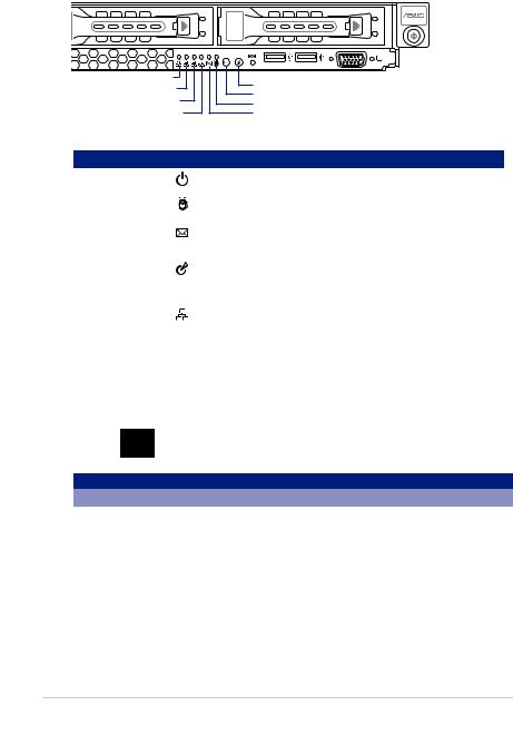
1.5Rear panel features
The rear panel includes the expansion slots, system power socket, and rear fans. The middle part includes the I/O shield with openings for the rear panel connectors on the motherboard.
RS300-E9-RS4
PS/2 keyboard/mouse port |
LAN port 5* |
Q-Code LED |
USB 2.0 ports USB 3.0 ports
VGA port
 Gigabit LAN port 4 Gigabit LAN port 3 Gigabit LAN port 2 Gigabit LAN port 1
Message LED |
Power button |
RS300-E9-PS4 |
|
PS/2 keyboard/mouse port |
LAN port 5* |
Serial port (optional) 
USB 2.0 ports
USB 3.0 ports
VGA port
|
Q-Code LED |
|
Gigabit LAN port 4 |
Message LED |
|
Gigabit LAN port 3 |
Power button |
|
Gigabit LAN port 2 |
||
|
||
Gigabit LAN port 1 |
|
*This port is for ASUS ASMB8-iKVM controller card only.
1-6 |
Chapter 1: Product Introduction |

1.6Internal features
The barebone server includes the basic components as shown.
1. Power supply and power fan
2. PCI Express slot Riser Card
3. ASUS P10S-C/4L/SYS
Server Board
4. System fans
5. SAS / SATA backplane (hidden)
6. HDD tray 1-4
7. Front I/O boards (hidden)
8. Slim-type optical drive
9. SSD Cage
10. Asset Tag
The barebone server does not include a floppy disk drive. Connect a USB floppy disk drive to any of the USB ports on the front or rear panel if you need to use a floppy disk.
Turn off the system power and detach the power supply before removing or replacing any system component.
WARNING
HAZARDOUS MOVING PARTS
KEEP FINGERS AND OTHER BODY PARTS AWAY
ASUS RS300-E9 Series |
1-7 |
1.7LED information
1.7.1Front panel LEDs
4 |
1 |
|
LAN 4 LED |
Location switch |
|
LAN 3 LED |
||
Power button |
||
LAN 2 LED |
||
Message LED |
||
LAN 1 LED |
||
HDD LED |
LED |
Icon |
Display status |
Description |
Power LED |
|
ON |
System power ON |
|
|
|
|
HDD Access LED |
|
OFF |
No activity |
|
Blinking |
Read/write data into the HDD |
|
|
|
||
Message LED |
|
OFF |
System is normal; no incoming event |
|
ON |
A hardware monitor event is indicated |
|
|
|
||
|
|
OFF |
Normal status |
Location LED |
|
Location switch is pressed |
|
|
ON |
||
|
|
(Press the location switch again to turn off) |
|
|
|
|
|
|
|
OFF |
No LAN connection |
LAN LEDs |
|
Blinking |
LAN is transmitting or receiving data |
|
|
ON |
LAN connection is present |
1.7.2LAN (RJ-45) LEDs
ACT/LINK LED SPEED LED
|
|
|
|
|
|
|
|
|
|
|
|
|
|
|
|
|
|
|
|
|
|
|
|
|
|
|
|
|
|
|
|
|
|
|
|
|
|
|
|
|
|
|
ACT/LINK LED |
|
SPEED LED |
||
Status |
Description |
Status |
Description |
||||
OFF |
No link |
OFF |
10 Mbps connection |
||||
GREEN |
Linked |
ORANGE |
100 Mbps connection |
||||
BLINKING |
Data activity |
GREEN |
1 Gbps connection |
||||
1-8 |
Chapter 1: Product Introduction |
1.7.3HDD status LED
HDD status LED
HDD Activity LED
SATA/SAS HDD LED Description
|
GREEN |
ON |
SATA/SAS HDD power ON |
|
|
|
|
|
RED |
ON |
HDD has failed and should be swapped |
HDD Status |
immediately |
||
LED |
GREEN/ |
Blinking |
RAID rebuilding |
|
RED |
||
|
|
|
|
|
GREEN/ |
OFF |
HDD not found |
|
RED |
||
|
|
|
|
HDD Activity |
GREEN |
Blinking |
Read/write data from/into the SATA/SAS HDD |
LED |
|
|
|
ASUS RS300-E9 Series |
1-9 |

1-10 |
Chapter 1: Product Introduction |
Hardware Information |
2 |
This chapter lists the hardware setup procedures that you have to perform when installing or removing system components.

2.1 Chassis cover
Removing the rear cover
1.Locate and remove the front side screws.
 Front side screw
2.Loosen the two thumbscrews on the rear panel to release the rear cover from the chassis.
Thumbscrews
3.Firmly hold the cover and slide it toward
the rear panel for about half an inch until it is disengaged from the chassis.
4. Lift the cover from the chassis.
5. To reattach the rear cover, reverse step
1 to 4.
A protection film is pre-attached to the system cover before shipping.
Please remove the protection film before turning on the system for proper heat dissipation.
2-2 |
Chapter 2: Hardware Information |

2.2Central Processing Unit (CPU)
The motherboard comes with a surface mount LGA1151 socket designed for the Intel® Xeon® E3-1200 v5 processor.
•Upon purchase of the motherboard, ensure that the PnP cap is on the socket and
the socket contacts are not bent. Contact your retailer immediately if the PnP cap is missing, or if you see any damage to the PnP cap/socket contacts/motherboard components. ASUS will shoulder the cost of repair only if the damage is shipment/ transit-related.
•The product warranty does not cover damage to the socket contacts resulting from incorrect CPU installation/removal, or misplacement/loss/incorrect removal of the PnP cap.
2.2.1Installing the CPU
To install the CPU:
1.Locate the CPU socket on the motherboard.
Before installing the CPU, ensure that the socket box is facing toward you and the load lever is on your right.
ASUS RS300-E9 Series |
2-3 |

2.Press the load lever with your thumb (A), then move it to the right (B) until it is released from the retention tab.
Do not remove the PnP cap yet from the CPU socket. Doing so may bend the pins of the socket.
3.Lift the load lever until the load plate is completely lifted.


 Load lever
Retention tab
Load plate
4.Position the CPU above the socket, ensuring that the gold triangle mark is
on the bottom-left corner of the socket, then fit the CPU notches to the socket's alignment keys.
The CPU fits in only one orientation. |
|
DO NOT force the CPU into the |
|
socket to prevent bending the pins on |
Gold |
the socket and damaging the CPU. |
triangle |
|
mark |
|
Alignment |
|
key |
CPU notches
Alignment key
2-4 |
Chapter 2: Hardware Information |

5.Close the load plate (A), ensuring that the front edge of the load plate slides
under the retention lock (B) then push |
Load lever |
|
|
down the load lever (C). |
|
Retention lock
6.Insert the load lever under the retention tab to remove the PnP cap from the CPU socket.
Load lever
 Retention tab
7.Apply some Thermal Interface Material
to the exposed area of the CPU that the heatsink will be in contact with, ensuring that it is evenly spread in a thin layer.
Some heatsinks come with pre-applied Thermal Interface Material. If so, skip this step.
The Thermal Interface Material is toxic and inedible. DO NOT eat it. If it gets into your eyes or touches
your skin, wash it off immediately and seek professional medical help.
ASUS RS300-E9 Series |
2-5 |
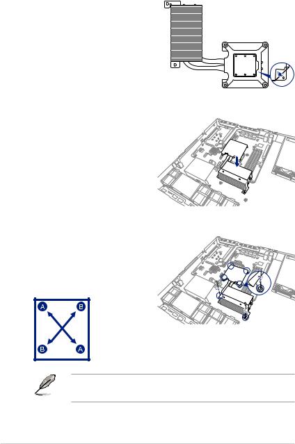
2.2.2Installing the CPU heatsink and airduct
To install the CPU heatsink:
1. Remove the protection sticker on the back of the CPU heatsink.
2.Place the heatsink on top of the
installed CPU, ensuring that the four fasteners match the holes on the motherboard.
3. Twist each of the four screws with a Phillips (cross) screwdriver just enough to attach the heatsink to the motherboard. When the four screws
are attached, tighten them one by one to completely secure the heatsink.
• Tighten the four heatsink screws in a diagonal sequence.
• Do not remove the mylar on the heatsink.
2-6 |
Chapter 2: Hardware Information |
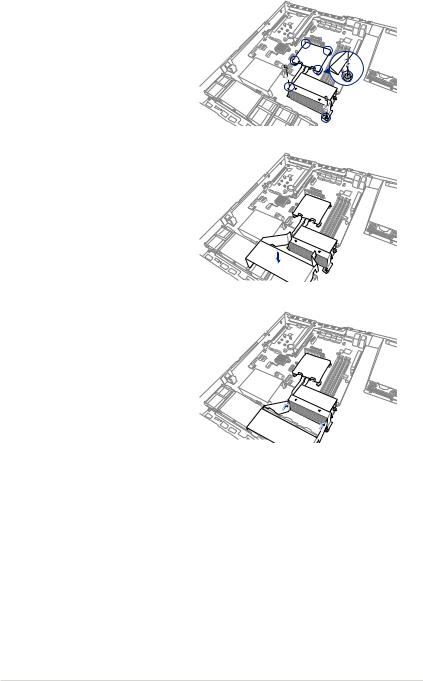
4.Secure the heat pipe and air duct to the server with two screws.
5.Insert the system fan mylar into the system fan, as shown in the right figure.
6.Insert the two tips of the system fan mylar into the CPU heatsink, as shown in the right figure.
ASUS RS300-E9 Series |
2-7 |

2.3System memory
2.3.1Overview
The motherboard comes with four Double Data Rate 4 (DDR4) Dual Inline Memory Modules (DIMM) sockets.
A DDR4 module is notched differently from a DDR, DDR2, or DDR3 module. DO NOT install a DDR, DDR2, or DDR3 memory module to the DDR4 slot.
The figure illustrates the location of the DDR4 DIMM sockets:
2.3.2Memory configurations
You may install Unbuffered DDR4 DIMMs into the DIMM sockets using the memory configurations in this section.
UDIMM
DIMM Slot |
DIMM Populated |
DIMM Type |
Speed |
Rank per DIMM |
|
Per Channel |
per Channel |
||||
|
|
|
|||
2 |
1 |
Unbuffered DDR4 |
2133 |
Single Rank, Dual Rank |
|
|
|
|
|
|
|
2 |
2 |
Unbuffered DDR4 |
2133 |
Single Rank, Dual Rank |
|
|
|
|
|
|
•Always install DIMMs with the same CAS latency. For optimum compatibility, it is
recommended that you obtain memory modules from the same vendor.
•Start installing the DIMMs in slots A2 and B2 (Blue).
2-8 |
Chapter 2: Hardware Information |
Loading...