


RS700-E7/RS4-C
Table of contents
 Loading...
RS700-E7/RS4-C
1U Rackmount Server
User Guide

E7586
Revised Edition V2
September 2012
Copyright © 2012 ASUSTeK COMPUTER INC. All Rights Reserved.
No part of this manual, including the products and software described in it, may be reproduced, transmitted,
transcribed, stored in a retrieval system, or translated into any language in any form or by any means,
except documentation kept by the purchaser for backup purposes, without the express written permission
of ASUSTeK COMPUTER INC. (“ASUS”).
ASUS provides this manual “as is” without warranty of any kind, either express or implied, including but not
limited to the implied warranties or conditions of merchantability or tness for a particular purpose. In no
event shall ASUS, its directors, ofcers, employees, or agents be liable for any indirect, special, incidental,
or consequential damages (including damages for loss of prots, loss of business, loss of use or data,
interruption of business and the like), even if ASUS has been advised of the possibility of such damages
arising from any defect or error in this manual or product.
Specications and information contained in this manual ae furnished for informational use only, and are
subject to change at any time without notice, and should not be construed as a commitment by ASUS.
ASUS assumes no responsibility or liability for any errors or inaccuracies that may appear in this manual,
including the products and software described in it.
Product warranty or service will not be extended if: (1) the product is repaired, modied or altered, unless
such repair, modication of alteration is authorized in writing by ASUS; or (2) the serial number of the
product is defaced or missing.
Products and corporate names appearing in this manual may or may not be registered trademarks or
copyrights of their respective companies, and are used only for identication or explanation and to the
owners’ benet, without intent to infringe.
ii

Contents
Safety information ..................................................................................... vii
About this guide ....................................................................................... viii
Chapter 1: Product introduction
1.1 System package contents ........................................................... 1-2
1.2 Serial number label ......................................................................
1.3 Systemspecications .................................................................
1.4 Front panel features .....................................................................
1.5 Rear panel features ......................................................................
1.6 Internal features ...........................................................................
1.7 LED information ...........................................................................
1.7.1 Front panel LEDs ............................................................
1.7.2 LAN (RJ-45) LEDs ..........................................................
1.7.3 HDD status LED ..............................................................
Chapter 2: Hardware setup
2.1 Chassis cover ............................................................................... 2-2
2.2 Central Processing Unit (CPU) ...................................................
2.2.1 Installing the CPU ...........................................................
2.2.2 Installing the CPU heatsink .............................................
2.3 System memory ...........................................................................
2.3.1 Overview .........................................................................
2.3.2 Memory Support List .......................................................
2.3.3 Memory Congurations ..................................................
2.3.4 Installing a DIMM on a single clip DIMM socket ...........
2.4 Hard disk drives .........................................................................
2.5 Expansion slot ............................................................................
2.5.1 Installing an expansion card to the riser card bracket ...
2.5.2 Conguring an expansion card .....................................
2.6 Cable connections .....................................................................
2.7 SATAII/SAS backplane cabling .................................................
2.8 Removable/optional components .............................................
2.8.1 System fans ..................................................................
2.8.2 Redundant power supply module .................................
2.8.3 Replacing optical drive (optional) ..................................
2.8.4 Installing ASUS PIKE RAID card (optional) ..................
1-2
1-3
1-5
1-5
1-6
1-7
1-7
1-7
1-8
2-3
2-3
2-8
2-9
2-9
2-9
2-11
2-13
2-14
2-16
2-16
2-19
2-20
2-21
2-22
2-22
2-23
2-24
2-25
iii

Contents
Chapter 3: Installation options
3.1 Friction Rail Kit Installation Guide ............................................. 3-2
3.1.1 Setting up the friction rail kit on the rack .........................
3.1.2 Mounting the server to the rack ......................................
Chapter 4: Motherboard info
4.1 Motherboard layouts .................................................................... 4-2
4.2 Jumpers ........................................................................................
4.3 Internal connectors ......................................................................
4.4 Internal LEDs ..............................................................................
Chapter 5: BIOS setup
5.1 Managing and updating your BIOS ............................................ 5-2
5.1.1 ASUS CrashFree BIOS 3 utility ......................................
5.1.2 ASUS EZ Flash 2 Utility ..................................................
5.1.3 BUPDATER utility
5.2 BIOS setup program ....................................................................
5.2.1 BIOS menu screen ..........................................................
5.2.2 Menu bar .........................................................................
5.2.3 Menu items .....................................................................
5.2.4 Submenu items ...............................................................
5.2.5 Navigation keys ...............................................................
5.2.6 General help ...................................................................
5.2.7 Conguration elds .........................................................
5.2.8 Pop-up window ...............................................................
5.2.9 Scroll bar .........................................................................
5.3 Main menu ....................................................................................
5.3.1 System Date [Day xx/xx/xxxx] .........................................
5.3.2 System Time [xx:xx:xx] ...................................................
5.4 Advanced menu .........................................................................
5.4.1 CPU Conguration ........................................................
5.4.2 CPU Power Management Conguration .......................
5.4.3 Chipset Conguration ...................................................
5.4.4 PCH SATA Conguration ..............................................
5.4.5 PCH SCU SAS Conguration .......................................
5.4.6 PCI Subsystem Settings ...............................................
............................................................ 5-4
3-2
3-4
4-4
4-8
4-14
5-2
5-3
5-6
5-7
5-7
5-8
5-8
5-8
5-8
5-8
5-8
5-8
5-9
5-9
5-9
5-10
5-10
5-12
5-14
5-22
5-23
5-23
iv

Contents
5.4.7 Onboard LAN Conguration .......................................... 5-29
5.4.8 USB Conguration ........................................................
5.4.9 Trusted Computing ........................................................
5.4.10 ACPI Settings ................................................................
5.4.11 WHEA Conguration .....................................................
5.4.12 APM ..............................................................................
5.4.13 Serial Port Console Redirection ....................................
5.4.14 ME Subsystem ..............................................................
5.4.15 Legacy Devices Conguration ......................................
5.4.16 Runtime Error Logging ..................................................
5.5 Server Mgmt menu .....................................................................
5.5.1 System Event Log .........................................................
5.5.2 BMC network conguration ...........................................
5.6 Event Logs menu .......................................................................
5.6.1 Change Smbios Event Log Settings .............................
5.7 Boot menu ..................................................................................
5.8 Monitor menu .............................................................................
5.9 Security menu ............................................................................
5.10 Tool menu ...................................................................................
5.11 Exit menu ....................................................................................
5-30
5-32
5-33
5-34
5-34
5-35
5-38
5-38
5-39
5-40
5-41
5-42
5-43
5-43
5-45
5-47
5-48
5-49
5-50
Chapter6: RAIDconguration
6.1 Setting up RAID ............................................................................ 6-2
6.1.1 RAID denitions ..............................................................
6.1.2 Installing hard disk drives ................................................
6.1.3 RAID controller selection ................................................
6.1.4 Setting the RAID item in BIOS ........................................
6.2 LSISoftwareRAIDCongurationUtility ....................................
6.2.1 Creating a RAID set ........................................................
6.2.2 Adding or viewing a RAID conguration ........................
6.2.3 Initializing the virtual drives ...........................................
6.2.4 Rebuilding failed drives .................................................
6.2.5 Checking the drives for data consistency .....................
6.2.6 Deleting a RAID conguration .......................................
6.2.7 Selecting the boot drive from a RAID set ......................
6.2.8 Enabling WriteCache ....................................................
6-2
6-2
6-3
6-3
6-4
6-5
6-11
6-12
6-16
6-18
6-21
6-22
6-23
v

Contents
6.3 Intel® Rapid Storage Technology enterprise SCU/SATA Option
ROM Utility ..................................................................................
6.3.1 Creating a RAID set ......................................................
6.3.2 Creating a Recovery set ...............................................
6.3.3 Deleting a RAID set ......................................................
6.3.4 Resetting disks to Non-RAID ........................................
6.3.5 Exiting the Intel
6.3.6 Rebuilding the RAID .....................................................
6.3.7 Setting the Boot array in the BIOS Setup Utility ............
®
6.4 Intel
Rapid Storage Technology enterprise Utility (Windows) 6-34
6.4.1 Creating a RAID set ......................................................
6.4.2 Change Volume Type ....................................................
6.4.3 Delete volume ...............................................................
6.4.4 Preferences ...................................................................
Chapter 7: Driver installation
7.1 RAID driver installation ............................................................... 7-2
7.1.1 Creating a RAID driver disk ............................................
7.1.2 Installing the RAID controller driver ................................ 7-5
®
7.2 Intel
7.3 Intel
7.4 VGA driver installation
7.5 Intel
7.6 Intel
7.7 Intel
7.8 Management applications and utilities installation ................
chipset device software installation ............................... 7-15
@
Network Connections Software installation.................. 7-18
®
C600 Series Chipset SCU SATA RAID Drivers ............... 7-24
®
Rapid Storage Technology enterprise 3.0 installation . 7-25
®
I350 Gigabit Adapters Driver installation ....................... 7-28
7.8.1 Running the support DVD .............................................
7.8.2 Drivers menu .................................................................
7.8.3 Utilities menu ................................................................
7.8.4 Make disk menu ............................................................
7.8.5 Contact information .......................................................
®
Rapid Storage Technology utility ........ 6-31
............................................................... 7-21
6-24
6-26
6-27
6-29
6-30
6-31
6-33
6-35
6-37
6-38
6-39
7-2
7-32
7-32
7-32
7-33
7-33
7-33
Appendix: Reference information
Z9PP-D24 block diagram ..........................................................................A-2
Notices .......................................................................................................A-3
ASUS contact information .......................................................................A-5
vi
Safety information
Electrical Safety
• Before installing or removing signal cables, ensure that the power cables for the
system unit and all attached devices are unplugged.
• To prevent electrical shock hazard, disconnect the power cable from the electrical
outlet before relocating the system.
• When adding or removing any additional devices to or from the system, ensure
that the power cables for the devices are unplugged before the signal cables
are connected. If possible, disconnect all power cables from the existing system
before you add a device.
• If the power supply is broken, do not try to x it by yourself. Contact a qualied
service technician or your dealer.
Operation Safety
• Any mechanical operation on this server must be conducted by certied or
experienced engineers.
• Before operating the server, carefully read all the manuals included with the server
package.
• Before using the server, ensure all cables are correctly connected and the power
cables are not damaged. If any damage is detected, contact your dealer as soon
as possible.
• To avoid short circuits, keep paper clips, screws, and staples away from
connectors, slots, sockets and circuitry.
• Avoid dust, humidity, and temperature extremes. Place the server on a stable
surface.
• If you encounter technical problems with the product, contact a qualied service
technician or your retailer.
This product is equipped with a three-wire power cable and plug for the user’s
safety. Use the power cable with a properly grounded electrical outlet to avoid
electrical shock.
Lithium-Ion Battery Warning
CAUTION! Danger of explosion if battery is incorrectly replaced. Replace
only with the same or equivalent type recommended by the manufacturer.
Dispose of used batteries according to the manufacturer’s instructions.
CD-ROM Drive Safety Warning
CLASS 1 LASER PRODUCT
Heavy System
CAUTION! This server system is heavy. Ask for assistance when moving or
carrying the system.
vii

About this guide
Audience
This user guide is intended for system integrators, and experienced users with at
least basic knowledge of conguring a server.
Contents
This guide contains the following parts:
1. Chapter 1: Product introduction
This chapter describes the general features of the server, including sections
on front panel and rear panel specications.
2. Chapter 2: Hardware setup
This chapter lists the hardware setup procedures that you have to perform
when installing or removing system components.
3. Chapter 3: Installation options
This chapter describes how to install optional components into the barebone
server.
4. Chapter 4: Motherboard information
This chapter gives information about the motherboard that comes with the
server. This chapter includes the motherboard layout, jumper settings, and
connector locations.
5. Chapter 5: BIOS information
This chapter tells how to change system settings through the BIOS Setup
menus and describes the BIOS parameters.
6. Chapter6:RAIDconguration
This chapter tells how to change system settings through the BIOS Setup
menus. Detailed descriptions of the BIOS parameters are also provided.
7 Chapter 7: Driver installation
This chapter provides instructions for installing the necessary drivers for
different system components.
viii

Conventions
To ensure that you perform certain tasks properly, take note of the following
symbols used throughout this manual.
DANGER/WARNING: Information to prevent injury to yourself when
trying to complete a task.
CAUTION: Information to prevent damage to the components when
trying to complete a task.
IMPORTANT: Instructions that you MUST follow to complete a task.
NOTE: Tips and additional information to help you complete a task.
Typography
Bold text
Italics
<Key> Keys enclosed in the less-than and greater-than
sign means that you must press the enclosed key.
Example: <Enter> means that you must press
the Enter or Return key.
<Key1+Key2+Key3> If you must press two or more keys simultaneously,
the key names are linked with a plus sign (+).
Example: <Ctrl+Alt+D>
Command
exactly as shown, then supply the required
item or value enclosed in brackets.
Example: At the DOS prompt, type the
command line:
Indicates a menu or an item to select.
Used to emphasize a word or a phrase.
Means that you must type the command
format A:/S
References
Refer to the following sources for additional information, and for product and
software updates.
1. ASUS Server Web-based Management (ASWM) user guide
This manual tells how to set up and use the proprietary ASUS server
management utility.
2. ASUS websites
The ASUS websites worldwide provide updated information for all ASUS
hardware and software products. Refer to the ASUS contact information.
ix

x

Chapter 1
This chapter describes the general
features of the chassis kit. It includes
sections on front panel and rear panel
specications.
Product introduction
1-
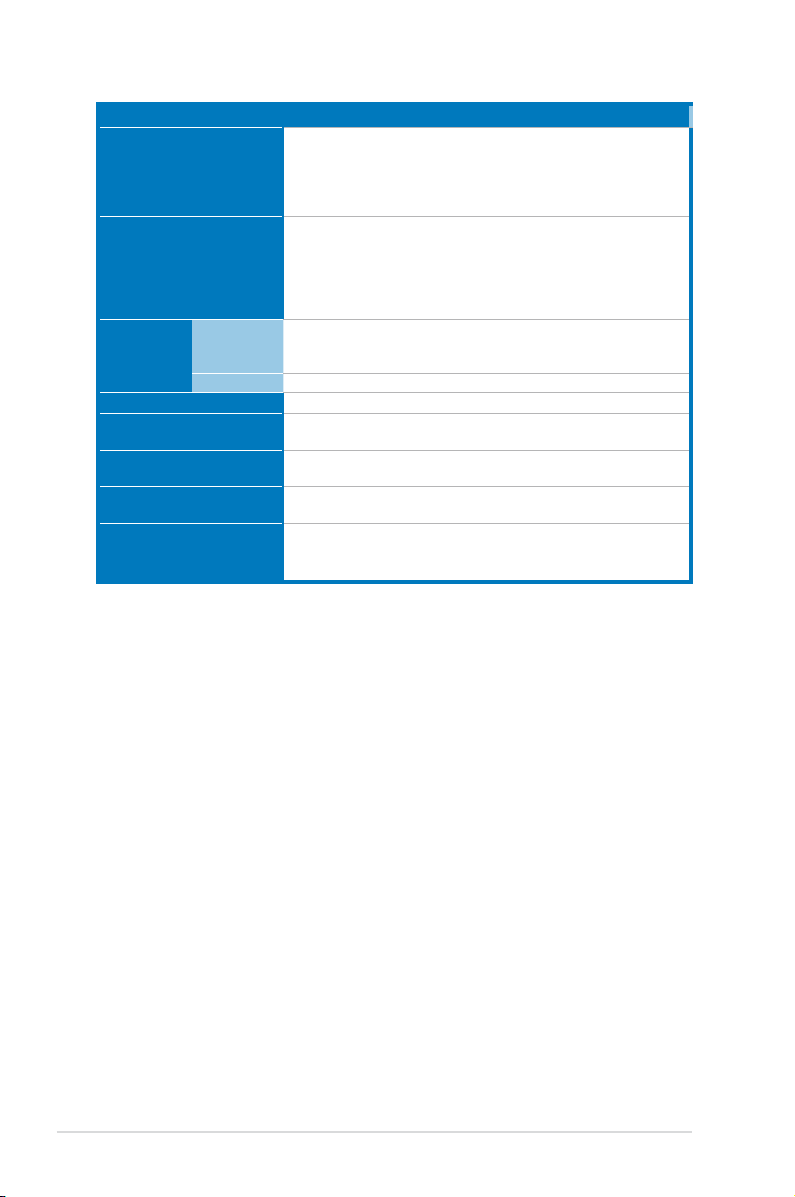
1.1 System package contents
Check your system package for the following items.
Model Name RS700-E7/RS4-C
Chassis ASUS R12D 1U Rackmount Chassis
Motherboard ASUS Z9PP-D24/2L Server Board
Component 2 x 550W Redundant Power Supply (varies by territories)
Accessories 1 x RS700-E7/RS4-C User’s Guide
Optional Items Second 550W Redundant Power Supply Module
*ASUS System Web-based Management
1 x SAS 3.5” HDD Backplane (BP4LX-R10A)
4 x hot-swap 3.5” HDD trays (varies by territories)
1 x Front I/O Board (LED board, FPB-AR14)
2 x Riser Card (RE16L-R12D, RE16R-R12D)
8 x System Fans (40 x 40 x 28mm)
1 x ASWM Enterprise User’s Guide
1 x RS700-E7/RS4-C Support CD
1 x ASWM Enterprise Support CD
1 x Bag of Screws
2 x CPU Heatsink (varies by territories)
2 x AC Power Cable
1 x Friction Rail Kit
CPU Heatsink
Slim type DVD-RW
If any of the above items is damaged or missing, contact your retailer.
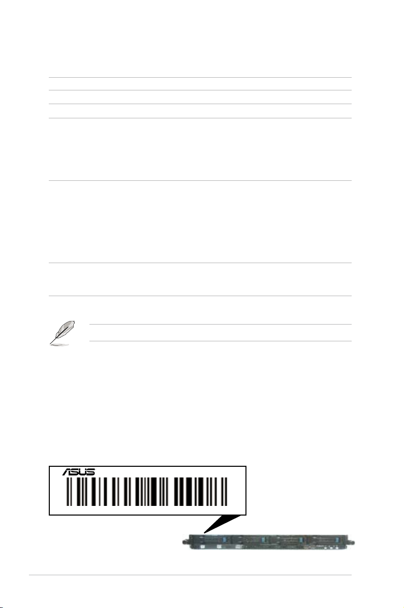
1.2 Serial number label
Before requesting support from the ASUS Technical Support team, you must
take note of the product’s serial number containing 14 characters such as
xxS0xxxxxxxxxx. See the gure below.
With the correct serial number of the product, ASUS Technical Support team
members can then offer a quicker and satisfying solution to your problems.
RS700-E7/RS4-C
xxS0xxxxxxxxxx
Chapter 1: Product introduction1-2
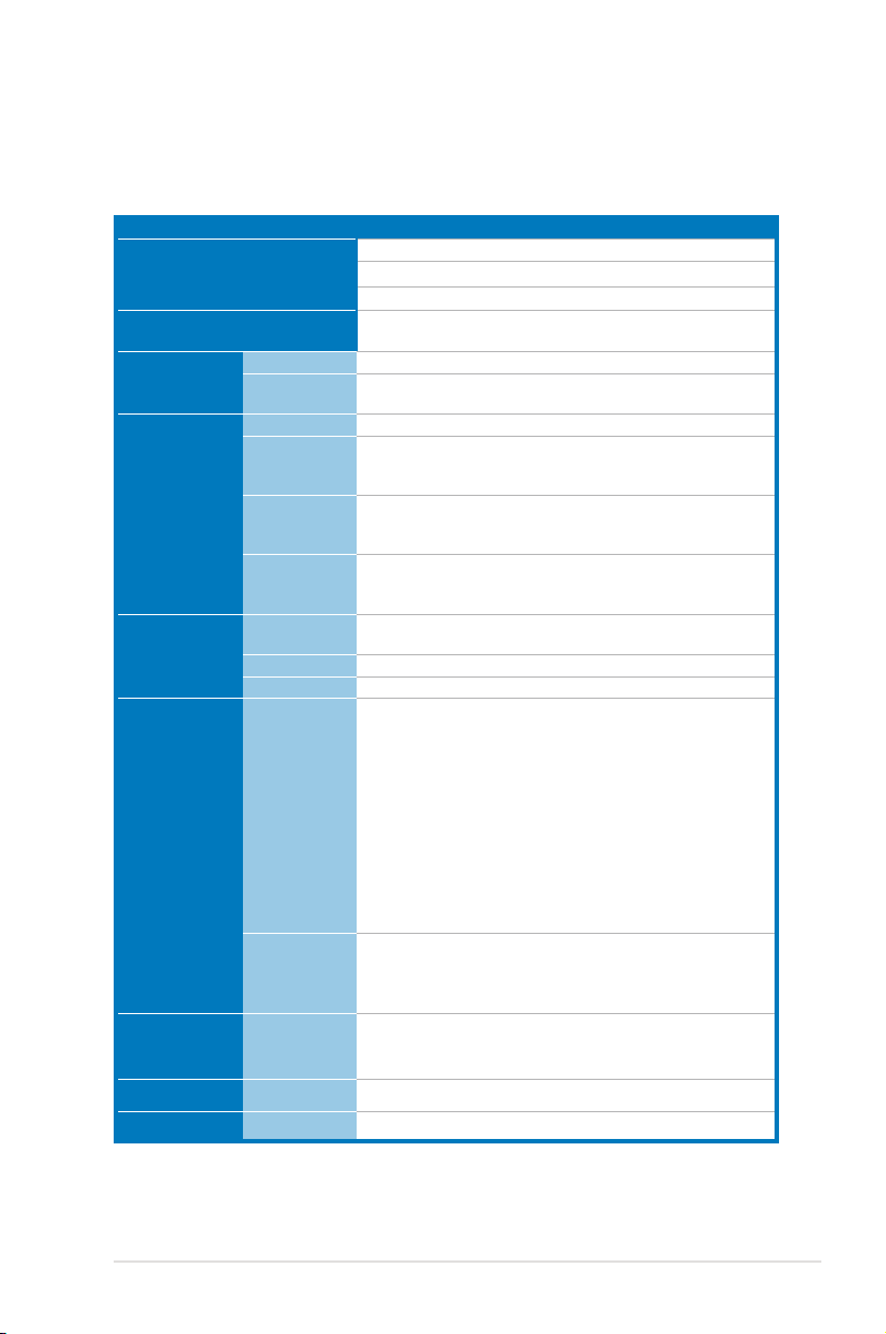
1.3 Systemspecications
The ASUS RS700-E7/RS4-C feature the ASUS Z9PP-D24 server board. The
server supports Intel® Socket-R LGA2011 Xeon® series processors with EM64T
technology, plus other latest technologies through the chipsets onboard.
Model Name RS700-E7/RS4-C
Processor / System Bus
Core Logic
ASUS Features
Memory
Expansion Slots
Storage
HDD Bays
Networking LAN
Graphic VGA
Smart Fan
ASWM
Enterprise
Total Slots
Capacity
Memory Type
Memory Size
Total PCI/PCI-X/
PCI-E Slots
Slot Type
Additional Slot
SATA Controller
SAS Controller
I = internal
A or S will be
hot-swappable
2 x Socket-R (LGA2011)
8/6/4 Core Intel® Xeon E5-2600 Series (Up to TDP=115W)
QPI 6.4 / 7.2 / 8.0 GT/s
Intel® C602 chipset
√
√
24 (4-channel per CPU, 12 DIMMs per CPU)
Maximum up to 192GB (RDIMM)
Maximum up to 128GB (UDIMM)
Maximum up to 192GB (LRDIMM)
DDR3 1600 / 1333 / 1066 / 800 Reg DIMM
DDR3 1333/ 1066 Unbuffered DIMM with ECC
DDR3 1333/ 1066 LRDIMM
2GB, 4GB, and 8GB (RDIMM)
2GB, 4GB, and 8GB (UDIMM)
8GB (LRDIMM)
2+1
2 x PCI-E G3 x16 (x16 Link) ( Full-height/Half-lengh)
1 x PIKE slot for storage enhancement
Intel® C602 chipset:
<AHCI>
2x SATA 3Gb/s ports
1x ISATA1 port (2 x SATA 3 Gb/s+2 x SATA 6Gb/s)
Intel RSTe (For Windows only)
- Supports S/W RAID 0,1,10 & 5)
LSI MegaRAID (for Linux / Windows):
- Supports software RAID 0, 1 & 10\
<SCU>
1x ISAS1 port (4 x SATA 3Gb/s)
Intel RSTe (For Windows only)
- Supports S/W RAID 0,1,10 & 5)
Optional:
ASUS PIKE 2008 8-port SAS2 6G RAID card
ASUS PIKE 2008/IMR 8-port SAS2 6G RAID card
ASUS PIKE 2108 8-port SAS2 6G H/W RAID card
4 x Hot-swap 3.5” SATA/SAS HDD Bays
1 x Dual-port Intel® I350-AM2 + 1 x Mgmt LAN
Aspeed AST2300 + 16MB VRAM
(continued on the next page)
ASUS RS700-E7/RS4-C 1-3
Model Name RS700-E7/RS4-C
3 x RJ-45 ports (1 for ASMB6-iKVM)
4 x USB 2.0 ports (Front x 2, Rear x 2)
Onboard I/O
1 x VGA port
1 x PS/2 keyboard port
1 x PS/2 mouse port
Windows® Server 2008 R2
Windows® Server 2008 Enterprise 32 / 64-bit
OS Support
Windows® Server 2003 R2 Enterprise 32 / 64-bit
RedHat® Enterprise Linux AS5.7, 6.1 32 / 64-bit
SuSE® Linux Enterprise Server 11.1 32 / 64-bit
(Subject to change without any notice)
Out of Band
Management
Solution
Remote
Hardware
Software
Dimension (HH x WW x DD)
Net Weight Kg (CPU, DRAM &
HDD not inclu ded)
Power Supply
Power Rating
On-Board ASMB6-iKVM for KVM-over-IP support
ASUS ASWM Enterprise
689.5mm x 444mm x 43.4mm (1U)
18 Kg
550W (Delta 80Plus Gold level) 1+1 Redundant Power Supply
(Default with one Power Supply Module)
Input:
550W: 100 - 127Vac / 7A, 200-240Vac / 3.4A, 47 - 63Hz, Class 1
Operation temperature: 10°C–35°C
Environment
Non operation temperature: -40°C–70°C
Non operation humidity: 20%–90% ( Non-condensing)
*Specicationsaresubjecttochangewithoutnotice.
®
Chapter 1: Product introduction1-4
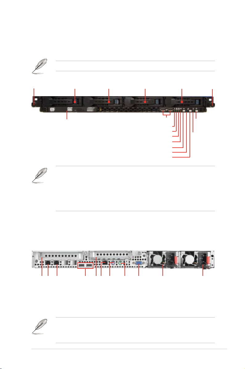
1.4 Front panel features
The barebone server displays a simple yet stylish front panel with easily accessible
features. The power and reset buttons, LED indicators, slim type optical drive, and
two USB ports are located on the front panel.
Refer to section 1.7.1 Front panel LEDs for the LED descriptions.
Rack screw
HDD 1 HDD 2 HDD 3 HDD 4
Optical drive
USB ports
HDD Access LED
LAN2 LED
LAN1 LED
Message LED
Reset button
Location LED
Location switch
Rack screw
Power
button
Power
LED
Factory shipment (default):
• Connect HDD1 - HDD4 to ISATA1 <AHCI> to support 2 x SATA 6Gb/s
(HDD1/HDD2) and 2 x SATA 3Gb/s (HDD3/HDD4). If you want SAS HDD
support, please upgrade with a PIKE RAID card.
• Refer to section
2.8.5 Installing ASUS PIKE RAID card
for the
descriptions.
1.5 Rear panel features
The rear panel includes the expansion slots, system power socket, and rear fans.
The middle part includes the I/O shield with openings for the rear panel connectors
on the motherboard.
LAN port 1
LAN port 2
Expansion slot
USB ports
PS/2 keyboard port
Expansion slot
DMLAN port*
PS/2 mouse port
VGA port
(Optional)
Redundant power
Second
connector
Power cord
• The ports for the PS/2 keyboard, PS/2 mouse, serial port, USB, VGA, and
Gigabit LAN do not appear on the rear panel if motherboard is not present.
• *The port is for ASUS ASMB6-iKVM controller card only.
ASUS RS700-E7/RS4-C 1-5
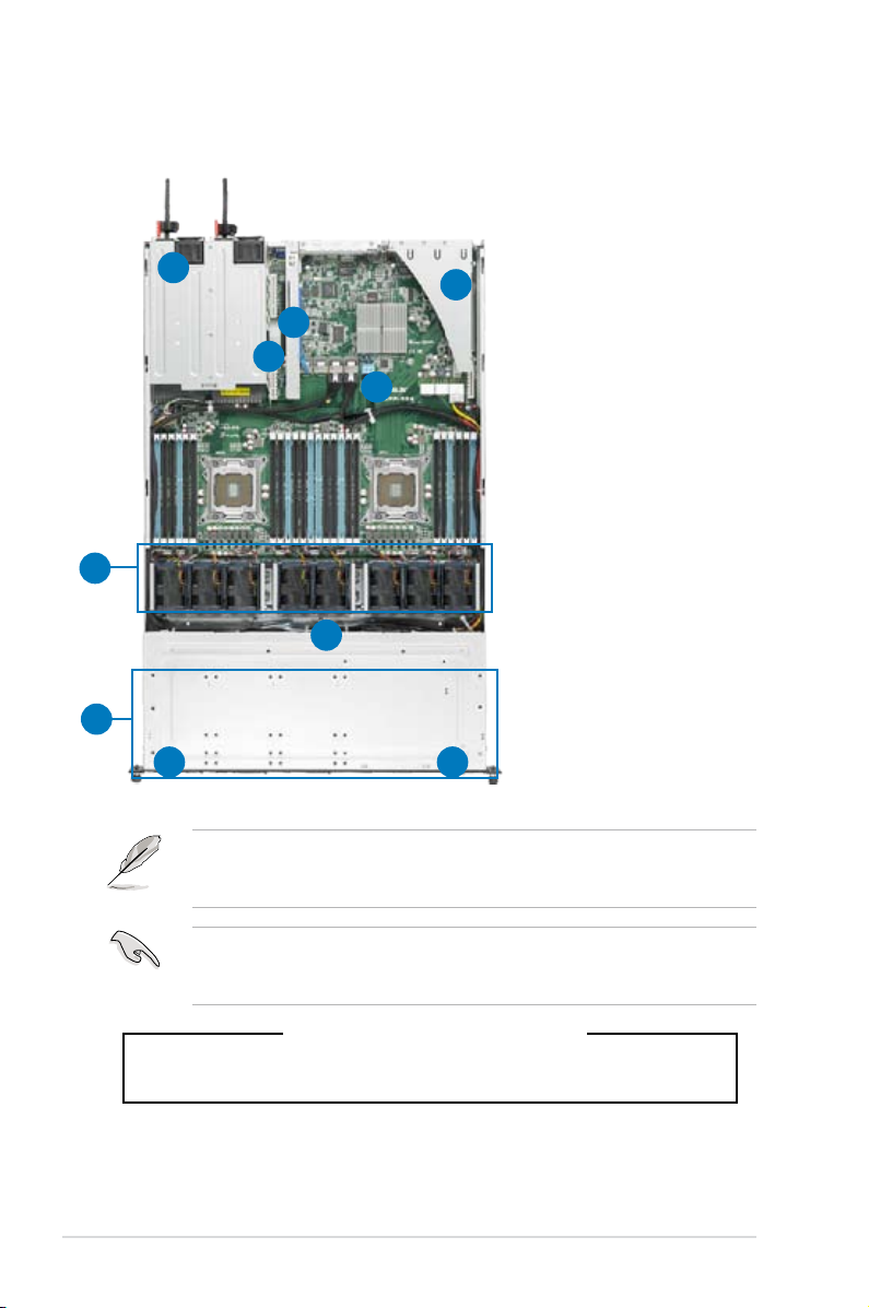
1.6 Internal features
The barebone server includes the basic components as shown.
1. Power supply and power
fan
1
2
2
3
4
5
6
7
2. PCI-E G3 x16 slot
(x16 link) (FH/HL)
3. PIKE Slot
4. ASUS Z9PP-D24 Server
Board
5. System fans
6. SATA/SAS backplane
(hidden)
7. 4 x HDD trays
8. Front LED Board
(FPB-AR14)
9. Slim-type optical drive
89
The barebone server does not include a oppy disk drive. Connect a USB oppy
disk drive to any of the USB ports on the front or rear panel if you need to use a
oppy disk.
A protection lm is pre-attached to the front cover before shipping. Please
remove the protection lm before turning on the system for proper heat
dissipation.
*WARNING
HAZARDOUS MOVING PARTS
KEEP FINGERS AND OTHER BODY PARTS AWAY
Chapter 1: Product introduction1-6
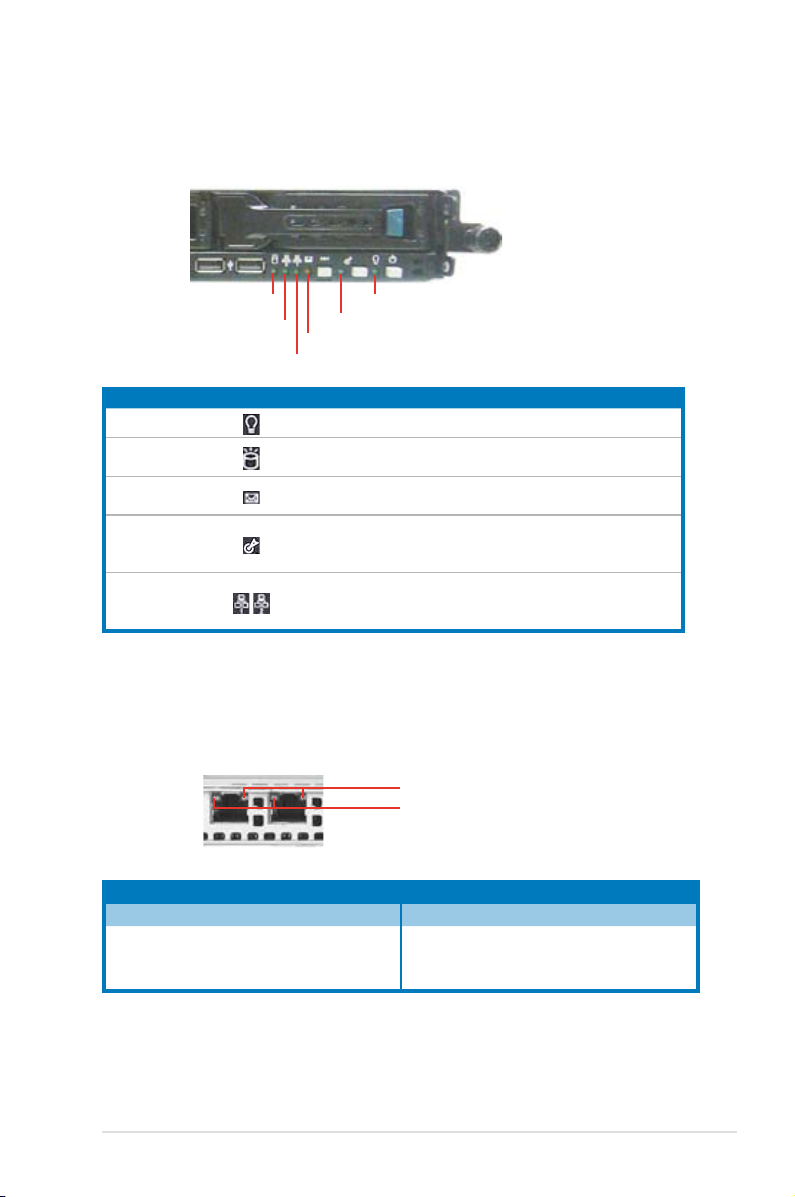
1.7 LED information
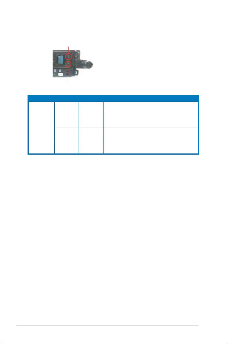
1.7.1 Front panel LEDs
HDD Access LED
LAN2 LED
LAN1 LED
LED Icon Display status Description
Power LED ON System power ON
HDD Access LED
Message LED
Location LED
LAN LEDs
Message LED
Power LED
Location LED
OFF
Blinking
OFF
Blinking
OFF
ON
OFF
Blinking
ON
No activity
Read/write data into the HDD
System is normal; no incoming event
ASWM indicates a HW monitor event
Normal status
Location switch is pressed
(Press the location switch again to turn off)
No LAN connection
LAN is transmitting or receiving data
LAN connection is present
1.7.2 LAN (RJ-45) LEDs
SPEED LED
ACT/LINK LED
ACT/LINK LED SPEED LED
Status Description Status Description
OFF No link OFF 10 Mbps connection
GREEN Linked ORANGE 100 Mbps connection
BLINKING Data activity GREEN 1 Gbps connection
ASUS RS700-E7/RS4-C 1-7
1.7.3 HDD status LED
HDD status LED
HDD Activity LED
SATAII/SAS HDD LED Description
GREEN ON SATAII/SAS HDD power ON
HDD Status
LED
HDD Activity
LED
RED ON
GREEN/
RED
GREEN Blinking Read/write data from/into the SATAII/SAS HDD
Blinking RAID rebuilding
HDD has failed and should be swapped
immediately
Chapter 1: Product introduction1-8

Chapter 2
This chapter lists the hardware setup
procedures that you have to perform
when installing or removing system
components.
Hardware setup
2-
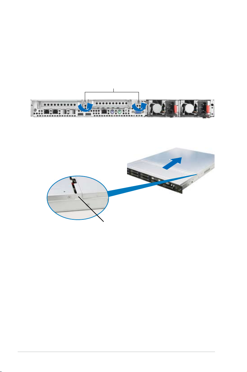
2.1 Chassis cover
Removing the rear cover
1. Loosen the two thumbscrews on the rear panel to release the rear cover from
the chassis.
Thumbscrews
2. Firmly hold the cover and slide it
toward the rear panel for about half
an inch until it is disengaged from
the chassis.
1/2 inch distance
3. Lift the cover from the chassis.
Chapter 2: Hardware setup2-2
®
Z9PP-D24
Z9PP-D24 CPU LGA2011 Socket
CPU2
CPU1
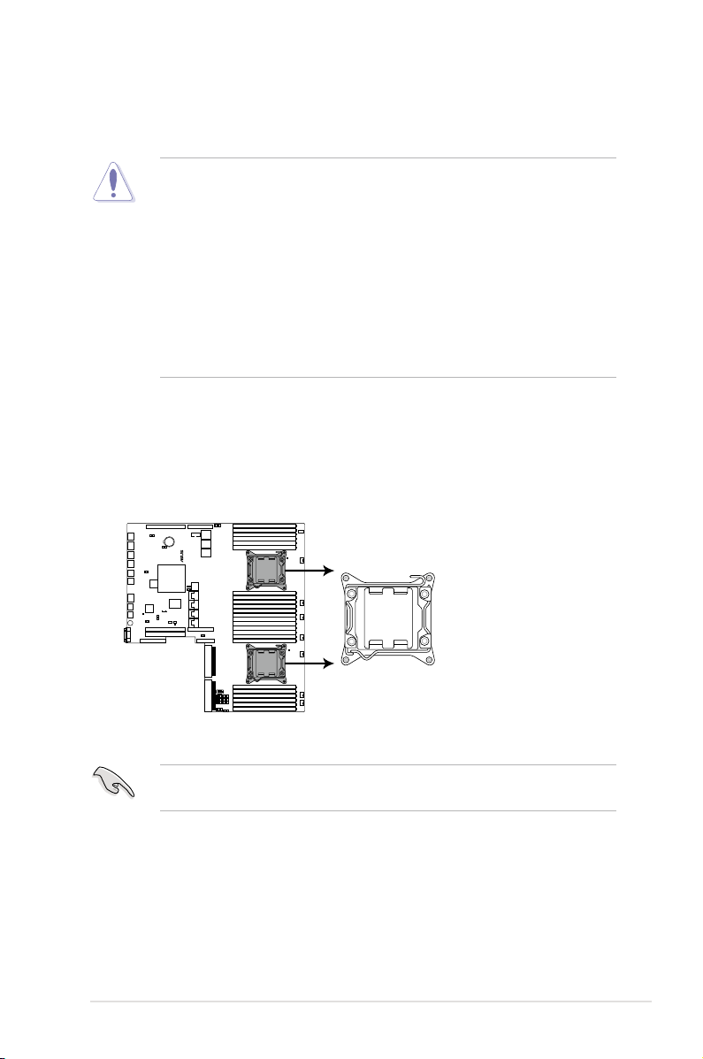
2.2 Central Processing Unit (CPU)
The motherboard comes with a surface mount LGA2011 socket designed for the
Intel® Xeon E5-2600 family processor.
• Upon purchase of the motherboard, ensure that the PnP cap is on
the socket and the socket contacts are not bent. Contact your retailer
immediately if the PnP cap is missing, or if you see any damage to the PnP
cap/socket contacts/motherboard components. ASUS will shoulder the cost
of repair only if the damage is shipment/transit-related.
• Keep the cap after installing the motherboard. ASUS will process Return
Merchandise Authorization (RMA) requests only if the motherboard comes
with the cap on the LGA2011 socket.
• The product warranty does not cover damage to the socket contacts
resulting from incorrect CPU installation/removal, or misplacement/loss/
incorrect removal of the PnP cap.
2.2.1 Installing the CPU
To install a CPU:
1. Locate the CPU socket on the motherboard.
Before installing the CPU, ensure that the socket box is facing towards you and
the load lever is on your left.
2-3ASUS RS700-E7/RS4-C
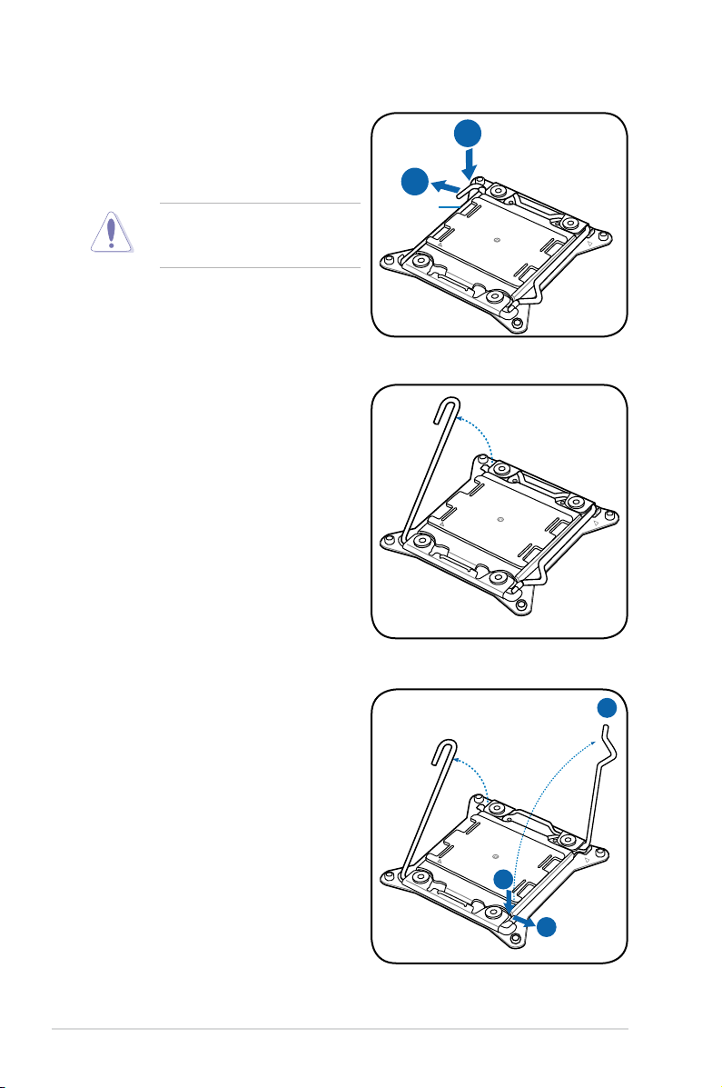
2. Press the left load lever with your
B
A
E
D
C
thumb (A), then move it to the left
(B) until it is released from the
retention tab.
To prevent damage to the socket
pins, do not remove the PnP cap
unless you are installing a CPU.
3. Slightly lift the load lever in the
direction of the arrow.
Load lever
4. Press the right load lever with your
thumb (C), then move it to the right
(D) until it is released from the
retention tab. Lift the load lever in
the direction of the arrow (E).
Chapter 2: Hardware setup2-4
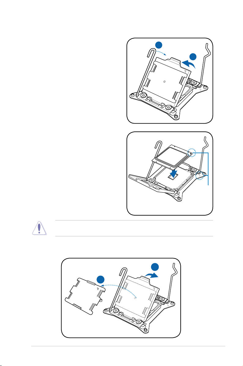
I
H
G
F
5. Push the left load lever (F) to lift the
load plate (G).
6. Position the CPU over the socket,
ensuring that the triangle mark is on
the top-right corner of the socket.
Triangle
mark
The CPU ts in only one correct orientation. DO NOT force the CPU into the
socket to prevent bending the connectors on the socket and damaging the CPU!
7. Remove the PnP cap (H) from the CPU socket and close the load plate (I).
2-5ASUS RS700-E7/RS4-C
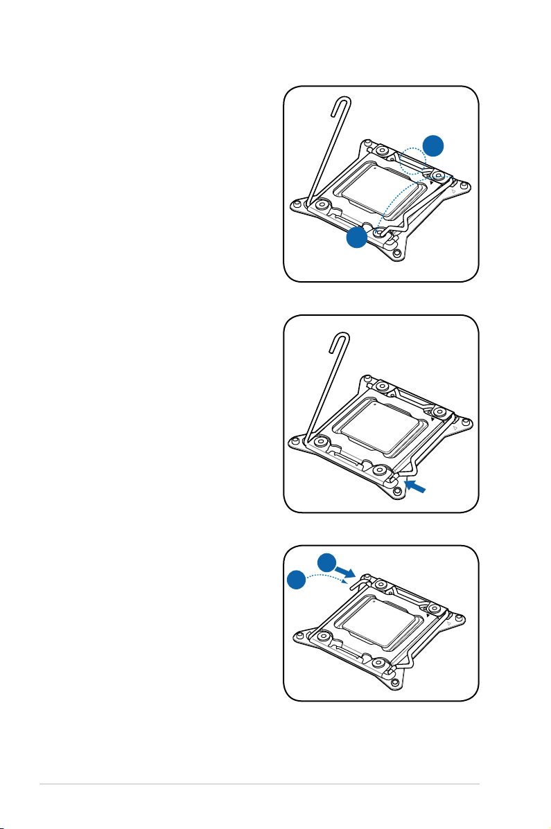
K
J
8. Push down the right load lever (J),
M
L
ensuring that the edge of the load
plate is xed by the lever (K).
9. Insert the right load lever under the
retention tab.
10. Push down the left load lever (L),
and then insert the lever under the
retention tab (M).
Chapter 2: Hardware setup2-6
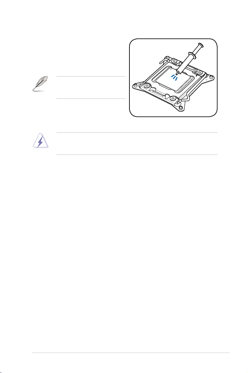
11. Apply some Thermal Interface
Material to the exposed area of
the CPU that the heatsink will be
in contact with, ensuring that it is
spread in an even thin layer.
Some heatsinks come with preapplied thermal paste. If so, skip
this step.
The Thermal Interface Material is toxic and inedible. DO NOT eat it. If it
gets into your eyes or touches your skin, wash it off immediately, and seek
professional medical help.
2-7ASUS RS700-E7/RS4-C
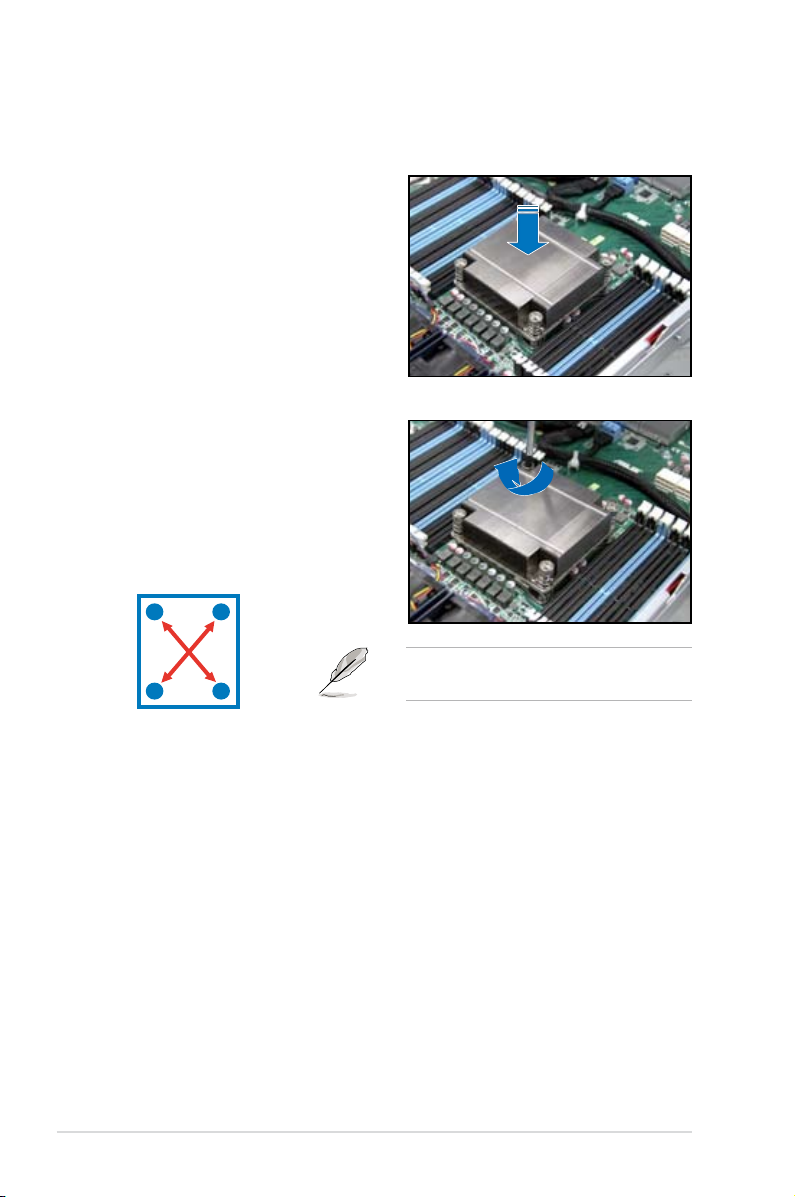
2.2.2 Installing the CPU heatsink
To install the CPU heatsink:
1. Place the heatsink on top of the
installed CPU, ensuring that the four
fasteners match the holes on the
motherboard.
2. Twist each of the four screws with
a Philips (cross) screwdriver just
enough to attach the heatsink to
the motherboard. When the four
screws are attached, tighten them
one by one to completely secure
the heatsink.
A
B
B
Tighten the four heatsink screws in a
A
diagonal sequence.
Chapter 2: Hardware setup2-8
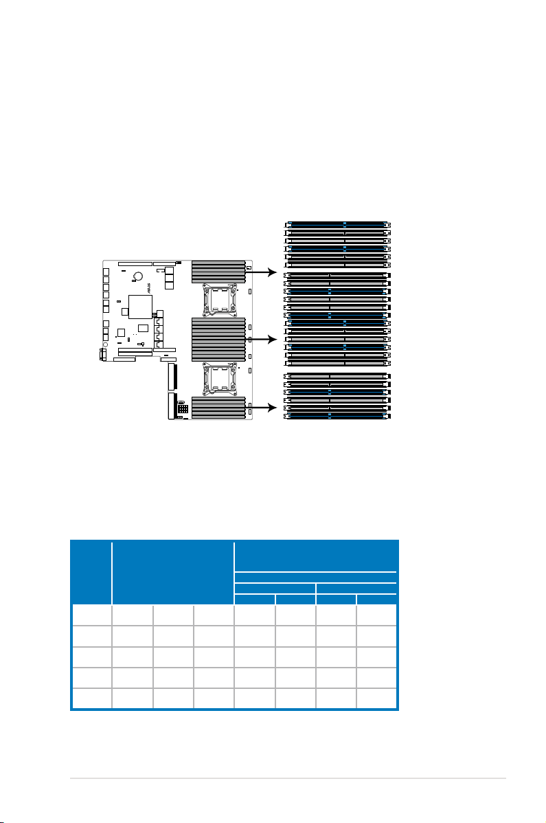
2.3 System memory
®
Z9PP-D24
Z9PP-D24 240-pin DDR3 DIMM sockets
DIMM_C3
DIMM_C2
DIMM_C1
DIMM_D3
DIMM_D2
DIMM_D1
DIMM_E1
DIMM_E2
DIMM_E3
DIMM_F1
DIMM_F2
DIMM_F3
DIMM_H2
DIMM_H3
DIMM_H1
DIMM_G3
DIMM_G2
DIMM_G1
DIMM_A2
DIMM_A1
DIMM_A3
DIMM_B1
DIMM_B2
DIMM_B3
2.3.1 Overview
The motherboard comes with 12 (per CPU) Double Data Rate 3 (DDR3) Dual Inline
Memory Modules (DIMM) sockets.
A DDR3 module has the same physical dimensions as a DDR2 DIMM but is
notched differently to prevent installation on a DDR2 DIMM socket. DDR3 modules
are developed for better performance with less power consumption.
The gure illustrates the location of the DDR3 DIMM sockets:
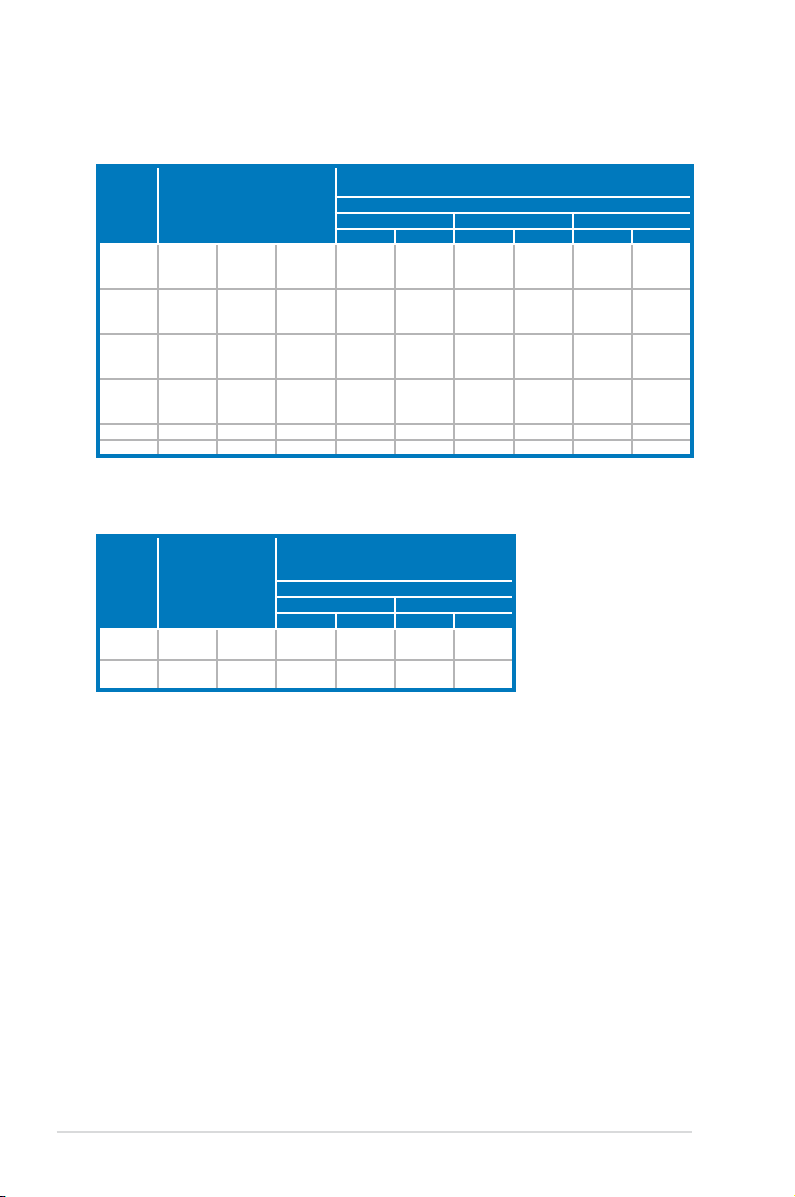
2.3.2 Memory Support List
Intel Xeon E5-2600 Series Processor UDIMM Memory Support List
Ranks
Per DIMM
and Data
Width
SRx8
Non-ECC
DRx8
Non-ECC
SRx16
Non-ECC
SRx8 ECC 1GB 2GB 4GB 1066
DRx8 ECC 2GB 4GB 8GB 1066
Memory Capacity Per DIMM
1GB 2GB 4GB N/A
2GB 4GB 8GB N/A
512MB 1GB 2GB N/A
Speed (MT/s) and Voltage Validated by Slot
Per Channel (SPC) and DIMM Per Channel
1.35V 1.5V 1.35V
(DPC)
3 Slots Per Channel
1DPC 2DPC
1066,
1333,
1066,
1333,
1066,
1333,
1066,
1333,
1066,
1333,
N/A
N/A
N/A
1066
1066
1.5V
1066,
1333,
1066,
1333,
1066,
1333,
1066,
1333,
1066,
1333,
2-9ASUS RS700-E7/RS4-C
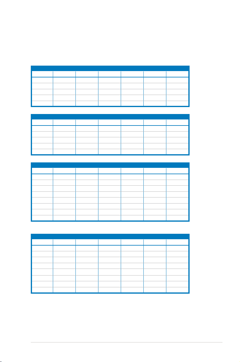
Intel Xeon E5-2600 Series Processor RDIMM Memory Support List
Ranks
Per DIMM
and Data
Width
SRx8 1GB 2GB 4GB
DRx8 2GB 4GB 8GB
SRx4 2GB 4GB 8GB
DRx4 4GB 8GB 16GB
QRx4 8GB 16GB 32GB 800 1066 800 800 N/A N/A
QRx8 4GB 8GB 16GB 800 1066 800 800 N/A N/A
Memory Capacity Per DIMM
Speed (MT/s) and Voltage Validated by Slot Per Channel (SPC) and
1DPC 2DPC 3DPC
1.35V 1.5V 1.35V
1066,
1333
1066,
1333
1066,
1333
1066,
1333
DIMM Per Channel (DPC)
3 Slots Per Channel
1066,
1066,
1333,
1066,
1333,
1066,
1333,
1066,
1333,
1600
1600
1600
1600
1333
1066,
1333
1066,
1333
1066,
1333
1.5V 1.35V 1.5V
1066,
1333,
1600
1066,
1333,
1600
1066,
1333,
1600
1066,
1333,
1600
N/A
N/A
N/A
N/A
800,
1066
800,
1066
800,
1066
800,
1066
Intel Xeon E5-2600 Series Processor LRDIMM Memory Support List
Speed (MT/s) and Voltage Validated by Slot
Ranks
Per DIMM
Memory Capacity Per
and Data
Width
QRx4
(DDP)*
QRx8 (P)** 8GB 16GB 1066
DIMM
16GB 32GB 1066
* DDP-Dual Die Package DRAM stacking.
** P-Planer monolithic DRAM die.
Per Channel (SPC) and DIMM Per Channel
1DPC and 2DPC 3DPC
1.35V 1.5V
(DPC)
3 Slots Per Channel
1.35V 1.5V
1066,
1333
1066,
1333
1066 1066
1066 1066
Chapter 2: Hardware setup2-10
2.3.3 MemoryCongurations
You may install 2GB, 4GB, 8GB, 16GB and 32GB* RDIMMs or 2GB, 4GB and 8GB*
with ECC/Non-ECC UDIMMs or 8GB, 16GB and 32GB* LR-DIMMs into the DIMM
sockets using the memory congurations in this section.
1CPUConguration(mustonCPU1)
1 DIMMs
2 DIMMs
4 DIMMs
8 DIMMs
12 DIMMs
1CPUConguration(mustonCPU1)
1 DIMMs
2 DIMMs
4 DIMMs
8 DIMMs
12 DIMMs
2CPUConguration
1 DIMMs
2 DIMMs
4 DIMMs
8 DIMMs
12 DIMMs
16 DIMMs
20 DIMMs
24 DIMMs
2CPUConguration
1 DIMMs
2 DIMMs
4 DIMMs
8 DIMMs
12 DIMMs
16 DIMMs
20 DIMMs
24 DIMMs
DIMM_A3 DIMM_A2 DIMM_A1 DIMM_B3 DIMM_B2 DIMM_B1
V V V V
V V V V V V
DIMM_C3 DIMM_C2 DIMM_C1 DIMM_D3 DIMM_D2 DIMM_D1
V V V V
V V V V V V
DIMM_A3 DIMM_A2 DIMM_A1 DIMM_B3 DIMM_B2 DIMM_B1
V V V V
V V V V
V V V V V V
V V V V V V
DIMM_C3 DIMM_C2 DIMM_C1 DIMM_D3 DIMM_D2 DIMM_D1
V V V V
V V V V
V V V V V V
V
V V
V V
V V
V
V
V V
V V
V V
V V
2-11ASUS RS700-E7/RS4-C
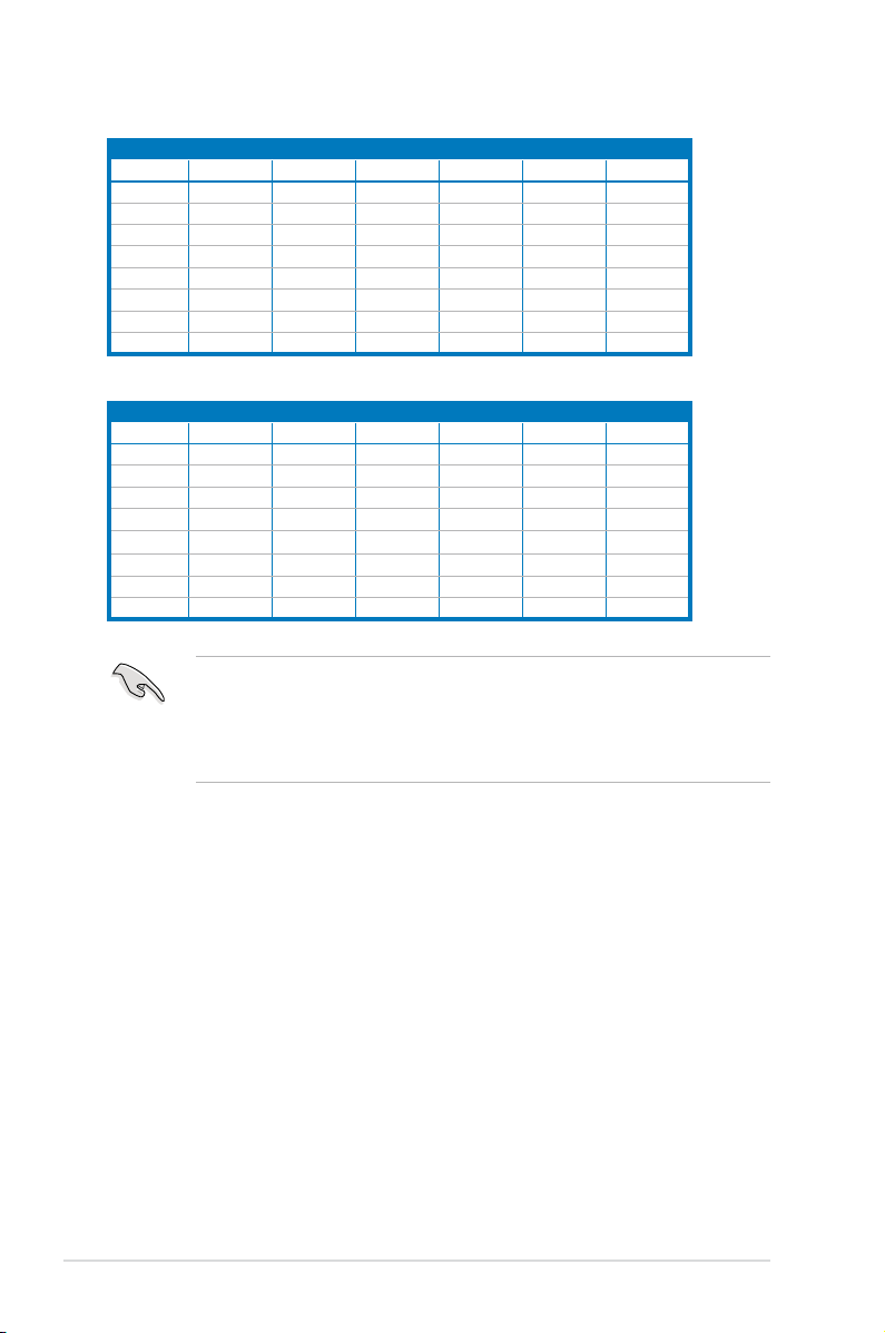
2CPUConguration
1 DIMMs
2 DIMMs
4 DIMMs
8 DIMMs
12 DIMMs
16 DIMMs
20 DIMMs
24 DIMMs
DIMM_E3 DIMM_E2 DIMM_E1 DIMM_F3 DIMM_F2 DIMM_F1
V V V V V V
V V V V V V
V
V V
V V
V V V V
V V V V
2CPUConguration
1 DIMMs
2 DIMMs
4 DIMMs
8 DIMMs
12 DIMMs
16 DIMMs
20 DIMMs
24 DIMMs
DIMM_G3 DIMM_G2 DIMM_G1 DIMM_H3 DIMM_H2 DIMM_H1
V V V V V V
• *For the latest update, please refer to ASUS Server AVL on the website.
• Start installing the DIMMs from slot A1 (light blue).
• Always install DIMMs with the same CAS latency. For optimum compatibility,
it is recommended that you obtain memory modules from the same vendor.
V V
V V
V V V V
V V V V
Chapter 2: Hardware setup2-12
Loading...