


 Loading...
RS500A-E10-PS4 RS500A-E10-RS4 RS500A-E10-RS12U

C18132
4.00
2021 3
© ASUSTeK Computer Inc. All rights reserved.
“ ”
“ ” “ ”
失之可能性。
述限制或排除條款可能對您不適用。
戶手冊將會隨之更新。本用戶手冊更新的詳細說明請您訪問華碩的客戶服務網http:// www.asus.com.cn/support 400-620-6655
或內容所有人所有且受當前知識產權相關法律及國際條約的保護。
1
2
ii

............................................................................................................................... |
vi |
........................................................................................................................................ |
vii |
............................................................................................................................ |
vii |
............................................................................................................................ |
vii |
............................................................................................................................ |
vii |
......................................................................................................................... |
viii |
........................................................................................................................... |
viii |
............................................................................................................................. |
ix |
................................................................................... |
ix |
................................................................................................................ |
x |
1.1 |
................................................................................................................... |
1-2 |
1.2 |
............................................................................................................................ |
1-3 |
1.3 |
........................................................................................................................ |
1-4 |
1.4 |
............................................................................................................................ |
1-6 |
1.5 |
............................................................................................................................ |
1-7 |
1.6 |
............................................................................................................................ |
1-8 |
1.7 |
LED ....................................................................................................... |
1-10 |
|
1.7.1 .................................................................................................. |
1-10 |
|
1.7.2 ............................................................................................. |
1-11 |
|
1.7.3 ............................................................................................. |
1-11 |
|
1.7.4 Q-Code ................................................................................................... |
1-12 |
2.1 |
............................................................................................................................ |
2-2 |
|
2.1.1 ...................................................................................... |
2-2 |
2.2 |
CPU ..................................................................................................... |
2-3 |
|
2.2.1 ............................................................................................... |
2-3 |
2.3 |
............................................................................................................................ |
2-7 |
|
2.3.1 ...................................................................................................................... |
2-7 |
|
2.3.2 ............................................................................................................. |
2-7 |
|
2.3.3 ........................................................................................................ |
2-8 |
|
2.3.4 ........................................................................................................ |
2-8 |
2.4 |
............................................................................................................................ |
2-9 |
2.5 |
.......................................................................................................................... |
2-15 |
|
2.5.1 ................................................................. |
2-15 |
|
2.5.2 PIKE II ............................................................................. |
2-17 |
|
2.5.3 PCIE-NVME2-OCuLink |
|
|
RS500A-E10-RS12U ................................................................... |
2-20 |
|
2.5.4 PCIE-NVME4-OCuLink |
|
|
RS500A-E10-RS12U ................................................................... |
2-23 |
|
2.5.5 M.2 ........................................................................................... |
2-25 |
|
2.5.4 ...................................................................................................... |
2-27 |
RS500A-E10 iii

|
2.5.5 ...................................................................................................... |
2-30 |
2.6 |
.......................................................................................................................... |
2-31 |
2.7 |
SATA/SAS ................................................................................... |
2-33 |
2.8 |
................................................................................................................. |
2-35 |
|
2.8.1 ........................................................................................................... |
2-35 |
|
2.8.2 PSU |
|
|
RS500A-E10-RS4 / RS500A-E10-RS12U ........................ |
2-36 |
|
2.8.3 RS500A-E10-RS4 / RS500A-E10-PS4 ........... |
2-37 |
3.1 |
................................................................................................. |
3-2 |
3.2 |
................................................................................................................... |
3-5 |
4.1 |
........................................................................................................................ |
4-2 |
4.2 |
........................................................................................................................ |
4-4 |
4.3 |
........................................................................................................................ |
4-8 |
4.4 |
................................................................................................................. |
4-11 |
BIOS
5.1 BIOS ........................................................................................ |
5-2 |
5.1.1 CrashFree BIOS 3 ..................................................................... |
5-2 |
5.1.2 EzFlash ........................................................................ |
5-3 |
5.1.3 BUPDATER ................................................................................... |
5-4 |
5.2 BIOS ................................................................................................................. |
5-6 |
5.2.1 BIOS ........................................................................................ |
5-7 |
5.2.2 .................................................................................................... |
5-7 |
5.2.3 ............................................................................................................. |
5-8 |
5.2.4 .................................................................................................................. |
5-8 |
5.2.5 ............................................................................................... |
5-8 |
5.2.6 ............................................................................................................. |
5-8 |
5.2.7 .................................................................................................................. |
5-8 |
5.2.8 ............................................................................................................. |
5-8 |
5.2.9 .................................................................................................................. |
5-8 |
5.3 Main .............................................................................................................. |
5-9 |
5.3.1 System Date [Day xx/xx/xxxx]............................................................... |
5-9 |
5.3.2 System Time [xx:xx:xx]............................................................................... |
5-9 |
5.4 Performance Tuning menu ................................................. |
5-10 |
5.5 Advanced menu ................................................................................ |
5-11 |
5.5.1 Trusted Computing...................................................................................... |
5-12 |
5.5.2 PSP ................................................................................................. |
5-12 |
5.5.3 APM................................................................................................................... |
5-13 |
5.5.4 Onboard LAN ...................................................................................... |
5-14 |
5.5.5 Serial Port Console Redirection ...... |
5-15 |
5.5.6 CPU ......................................................................................................... |
5-17 |
iv

5.5.7 PCI PCI Subsystem Settings ................................... |
5-18 |
5.5.8 USB USB Configuration .......................................................... |
5-19 |
5.5.9 CSM ......................................................................................................... |
5-20 |
5.5.10 NVMe NVMe Configuration ............................................... |
5-21 |
5.5.11 SATA ................................................................................................... |
5-22 |
5.5.12 Tls Auth .............................................................................................. |
5-22 |
5.5.13 Network Stack Configuration ..................... |
5-23 |
5.5.14 AMD ................................................................................... |
5-24 |
5.5.15 iSCSI ..................................................................................................... |
5-24 |
5.6 .......................................................................................................................... |
5-25 |
5.7 Security menu ............................................................................... |
5-26 |
5.8 Boot menu .......................................................................................... |
5-30 |
5.9 Tool menu ........................................................................................... |
5-31 |
5.10 BIOS Exit ......................................................................................... |
5-31 |
5.11 AMD CBS .......................................................................................................... |
5-33 |
5.11.1 CPU Common Options............................................................................ |
5-33 |
5.11.2 DF Common Options................................................................................ |
5-34 |
5.11.3 UMC Common Option............................................................................. |
5-35 |
5.11.4 NBIO Common Options........................................................................... |
5-38 |
5.11.5 FCH Common Options............................................................................ |
5-41 |
5.11.6 NTB Common Options............................................................................ |
5-42 |
5.12 Event Logs menu ................................................................. |
5-43 |
5.12.1 Smbios .................................................................... |
5-43 |
5.12.2 View Smbios Event Log......................................................................... |
5-43 |
5.13 Server Mgmt menu ......................................................... |
5-44 |
6.1 ............................................................................................ |
6-2 |
KRPA-U16/SYS ...................................................................................................... |
A-2 |
....................................................................................................................... |
A-4 |
RS500A-E10 v

體本身的安全。
內部零件的損壞。
路。
IC
Power Supply unit HDD DC Fan
掉。
35
池。
vi

之後再安裝電源線。
擊生成。
能夠連接一台不斷電系統UPS
帶的靜電消除。
IC
器金屬平面部份碰觸。
RS500A-E10 vii

RS300-E10
頭。
Jumper
BIOS
BIOS BIOS
viii
作可能會對產品造成損害。
完成一項或多項軟硬件的安裝或設置。
項工作的訣竅和其他額外的信息。
1.
http://w3.asus.com.cn
2.
RS500A-E10 ix
30
|
|
|
|
|
|
|
|
|
|
|
|
|
|
|
|
(Pb) |
(Hg) |
(Cd) |
|
|
|
||
|
(Cr(VI)) |
(PBB) |
(PBDE) |
||||
|
|
|
|
|
|||
|
x |
o |
o |
|
o |
o |
o |
|
|
||||||
|
|
|
|
|
|
|
|
|
x |
o |
o |
|
o |
o |
o |
|
|
||||||
|
|
|
|
|
|
|
|
|
|
|
|
|
|
|
|
|
o |
o |
o |
|
o |
o |
o |
|
|
|
|
|
|
|
|
|
x |
o |
o |
|
o |
o |
o |
|
x |
o |
o |
|
o |
o |
o |
|
x |
o |
o |
|
o |
o |
o |
|
x |
o |
o |
|
o |
o |
o |
|
x |
o |
o |
|
o |
o |
o |
|
x |
o |
o |
|
o |
o |
o |
|
x |
o |
o |
|
o |
o |
o |
|
|
||||||
|
|
|
|
|
|
|
|
|
|
|
|
|
|
|
|
SJ/T 11364
○ GB/T 26572
× GB/T 26572
2.2011/65/EU
CSR Corporate Social Responsibility http://csr.asus.com/english/Takeback. htm
x
1
前、後面板以及內部功能的總體介紹。
1.1
|
RS500A-E10-PS4 RS500A-E10-RS4 RS500A-E10-RS12U |
|
|
|
R10E 1U |
|
|
|
KRPA-U16/SYS |
|
|
|
1 x 650W RS500A-E10-PS4 |
|
1 x 1+1 650W RS500A-E10-RS4 RS500A- |
|
E10-RS12U |
|
4 x 3.5 2.5 RS500A-E10-PS4 |
|
RS500A-E10-RS4 |
|
12 x 2.5 RS500A-E10-RS12U |
|
1 x SAS/SATA RS500A-E10-PS4 RS500A-E10-RS4 |
|
1 x SAS/SATA/NVMe RS500A-E10-RS12U |
|
1 x PCI-E |
|
1 x I/O |
|
6 x 40mm x 28mm |
|
1 x RS500A-E10-RS4 RS500A-E10- |
|
RS12U |
|
1 x 4 oculink RS500A-E10-RS12U |
|
|
|
1 x |
|
|
|
1 x AC RS500A-E10-PS4 |
|
2 x AC RS500A-E10-RS4 RS500A-E10-RS12U |
|
|
|
1 x CPU |
|
1 x |
|
DVD / DVD-RW |
|
|
商聯絡。
1-2
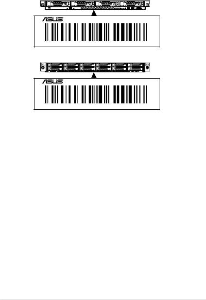
1.2
12 xxS0xxxxxxxx
RS500A-E10 Series
xxS0xxxxxxxx
RS500A-E10 Series
xxS0xxxxxxxx
RS500A-E10 1-3

1.3
RS500A-E10 1U KRPA-U16/SYS
AMD EPYC™ 7002 & 7003
|
|
RS500A-E10-PS4 |
RS500A-E10-RS4 |
RS500A-E10-RS12U |
|||
|
|
|
|
|
|
|
|
|
|
1 x Socket SP3 LGA 4094 |
|
||||
/ |
AMD EPYC™ 7002 & 7003 TDP |
||||||
|
|
225W |
|
||||
|
|
|
|
|
|
||
|
|
16 CPU 8 CPU 2 |
|||||
|
|
|
|
|
|||
|
|
2048GB |
|
||||
|
|
|
|
||||
|
|
DDR4 3200/2933/2666 RDIMM/LR-DIMM/LR-DIMM |
|||||
|
3DS |
|
|||||
|
|
|
|||||
|
|
|
|
|
|||
|
32GB 16GB 8GB 4GB RDIMM |
|
|||||
|
|
64GB 32GB LRDIMM |
|
||||
|
|
128GB 64GB LRDIMM 3DS |
|
||||
|
|
* w3.asus.com.cn AVL |
|||||
|
|
|
|
||||
|
|
|
|
|
|
|
|
|
PCI/PCI-E |
2+1 |
|
|
|
|
|
|
|
|
|
||||
|
|
1 x PCI-E 4.0 x16 x16 link RS12-U |
|||||
|
|
LP |
|
||||
|
1 x PCI-E 4.0 x16 x8 link RS12-U |
||||||
|
|||||||
|
|
|
|
||||
|
|
1 x OCP 2.0 Mezzanine x16 link |
|
||||
|
|
|
|
|
|||
|
SATA |
CPU |
|
||||
|
|
|
|
|
|||
|
|
|
|
||||
|
SAS |
PIKE II 3008 8 SAS HBA |
|
||||
|
PIKE II 3108 8 SAS HW RAID |
||||||
|
|||||||
|
|
||||||
|
|
12G SAS |
|
||||
|
|
|
|
|
|
|
|
|
NVMe |
N/A |
|
CPU |
|||
|
|
|
|||||
|
|
|
|
|
|
||
|
|
|
|
|
|
|
|
|
|
|
|
|
|
12 x 2.5 |
|
|
I = |
4 x 3.5 2.5 |
|
|
|||
A S = |
( SATA/SAS) |
|
( SATA/ |
||||
|
|
||||||
|
|
|
|
|
|
SAS/NVMe) |
|
|
|
|
|
|
|
|
|
|
|
2 x 1GbE LAN |
|
||||
|
|
1 x |
|
||||
|
|
OCP |
|
||||
- 2 or 4 x 1G |
|
||||||
|
|
|
|||||
|
|
- 2x 10G |
|
||||
|
|
- 2x 25G |
|
||||
|
|
Aspeed AST2500 64MB |
|
||||
|
|
|
|
|
|
|
|
1-4

|
|
RS500A-E10- |
RS500A-E10- |
RS500A-E10- |
|
|
PS4 |
RS4 |
RS12U |
||
|
|
||||
|
|
|
|
|
|
/ |
1 x (DVD-RW) |
N/A |
|||
/ |
2 x USB 3.0 |
N/A |
|||
1 x VGA |
|||||
|
|
|
|||
|
|
2 x USB 3.0 |
|
||
|
|
1 x VGA |
|
||
/ |
2 x RJ-45 GbE |
|
|||
|
|
1 x RJ-45 |
|
||
|
|
1 x |
|
|
|
|
|
|
|
|
|
|
|
|
|
|
|
|
|
|
|
- 1 x / |
|
|
|
|
|
|
|
|
|
|
|
- 1 x Q-Code/ |
|
|
|
|
Port 80 |
||
|
|
- 1 x / |
|||
|
|
- 1 x Location |
|||
|
|
- 1 x Q-Code/Port 80 |
|||
|
|
|
|||
|
|
|
|
||
|
|
- 1 x Location |
|
||
|
|
|
|
||
|
|
|
|
- 1 x / |
|
|
|
|
|
||
/ |
- 1 x / |
|
|||
|
|
- 1 x Location / |
- 1 x |
||
|
|
- 1 x |
|
- 4 x |
|
|
|
- 1 x |
|
LED1- |
|
|
|
- 4 x LED1-2 |
2 |
||
|
|
, 3-4 |
|||
|
|
, 3-4 OCP |
|||
|
|
OCP |
|||
|
|
|
|
||
|
|
|
|
|
|
|
|
|
|
- 1 x Location |
|
|
|
|
|
|
|
|
|
http://w3.asus.com.cn |
|||
|
|
|
|
||
|
|
|
|
||
|
|
ASUS Control Center |
|
||
|
|
|
|
||
|
|
|
|
||
|
ASMB9-iKVM KVM-over-IP |
||||
|
|||||
|
|
|
|
||
|
|
BSMI CE FCC |
|
|
|
|
|
|
|
||
x x |
615 x 444 x 44mm 1U |
|
|||
|
|
|
|
||
|
10.0 |
11.0 |
11.5 |
||
|
|
||||
|
|
|
|
||
|
|
|
|
||
|
16.0 |
17.0 |
17.5 |
||
|
|
||||
|
|
|
|
||
|
|
|
|
|
|
|
|
650W 80 |
|
|
|
|
|
PLUS Platinum |
1+1 650W 80 PLUS Platinum |
||
|
|
|
|
|
|
|
100- |
100-127/200-240Vac, |
|||
|
|
127/200-240 |
7.8A/3.8A(for each inlet), 50~60Hz |
||
|
|
Vac, 9A/5A, 50- |
or 240Vdc, 4.6A |
|
|
|
|
60Hz, Class I |
|
|
|
|
|
|
|
|
|
|
|
10 – 35 |
|
||
|
|
-40 – 70 |
|
||
|
|
20% – 90% |
|
||
*
RS500A-E10 1-5

1.4
LED USB
LED 1.7.1
RS500A-E10-RS4 / RS500A-E10-PS4
|
|
|
|
||
|
1 |
2 |
3 |
4 |
|
|
|
|
|
|
|
|
|
|
|
|
|

 4
4  Asset tag
321
USB 3.0
Reset Location
RS500A-E10-RS12U
|
|
|
|
|
|
|
|
|
|
|
10 |
12 |
|||||||||||
|
|
1 |
3 |
5 |
7 9 |
11 |
|
||||||||||||||||
|
|
|
|
|
|
|
|
|
|
|
|
|
|
|
|
|
|
|
|
|
|
|
|
|
|
|
|
|
|
|
|
|
|
|
|
|
|
|
|
|
|
|
|
|
|
|
|
|
|
|
|
|
|
|
|
|
|
|
|
|
|
|
|
|
|
|
|
|
|
|
|
|
|
|
|
|
|
|
|
|
|
|
|
|
|
|
|
|
|
|
|
|
|
|
|
|
|
|
|
|
|
|
|
|
|
|
|
|
|
|
|
|
|
|
|
|
|
|
|
|
|
|
|
|
|
|
|
|
|
|
|
|
|
|
|
|
|
|
|
|
|
|
|
|
|
|
|
|
|
|
|
|
|
|
|
|
|
|
|
|
|
|
|
|
|
|
|
|
|
|
|
|
|
2 |
4 |
6 |
8 |
||
|
|
|
|
|
|
Asset tag

Location
12
1-6
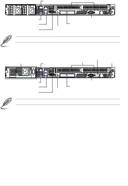
1.5
RS500A-E10-RS4 / RS500A-E10-RS12U
|
|
|
|
|
|
|
|
|
|
|
|
|
PCI-E |
Q-Code |
|||||||||
|
|
iKVM * |
|
|
|
|
|
Locate |
|||||||||||||||
|
|
|
|
|
|
||||||||||||||||||
|
|
|
|
|
|
|
|
|
|
|
|
|
|
|
|
||||||||
|
|
|
|
|
|
|
|
|
|
|
|
|
|
|
|
|
|
|
|
|
|
|
|
|
|
|
|
|
|
|
|
|
|
|
|
|
|
|
|
|
|
|
|
|
|
|
|
|
|
|
|
|
|
|
|
|
|
|
|
|
|
|
|
|
|
|
|
|
|
|
|
|
|
|
|
|
|
|
|
|
|
|
|
|
|
|
|
|
|
|
|
|
|
|
|
|
|
|
|
|
|
|
|
|
|
|
|
|
|
|
|
|
|
|
|
|
|
|
|
|
|
|
|
|
|
|
|
|
|
|
|
|
|
|
|
|
|
|
|
|
|
|
|
USB 3.0 Gigabit 12 VGA
OCP 2.0
* ASMB9-iKVM
RS500A-E10-PS4 |
|
|
||
|
|
PCI-E |
Q-Code |
|
|
iKVM * |
Locate |
||
|
|
|
||
USB 3.0 |
|
|||
Gigabit |
1 |
|||
OCP 2.0 |
||||
|
2 |
|||
|
|
|||
VGA |
|
|||
|
|
|||
* ASMB9-iKVM
RS500A-E10 1-7
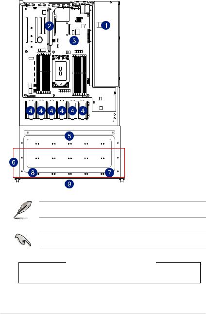
1.6 |
|
|
|
RS500A-E10-RS4 / RS500A-E10-PS4 |
|
1. |
|
2. |
PCI Gen4 x16/ |
|
x8 link |
3. |
KRPA-U16/SYS |
|
|
4. |
|
5. |
SAS / SATA |
6. |
4 x 3.5 |
7. |
I/O |
8. |
|
9. Asset Tag |
|
|
|
USB USB |
|
開。
*
1-8

RS500A-E10-RS12U |
|
1. |
|
2. |
PCI Gen4 x16/ |
|
x8 link |
3. |
KRPA-U16/SYS |
|
|
4. |
|
5. |
SAS / SATA / NVMe |
|
|
6. |
12 x 2.5 |
7. |
I/O |
8. |
Asset Tag |
9. |
PCIE-NVME4-OCuLink |
10. |
PCIE-NVME2-OCuLink |
|
|
USB USB |
|
開。
*
RS500A-E10 1-9
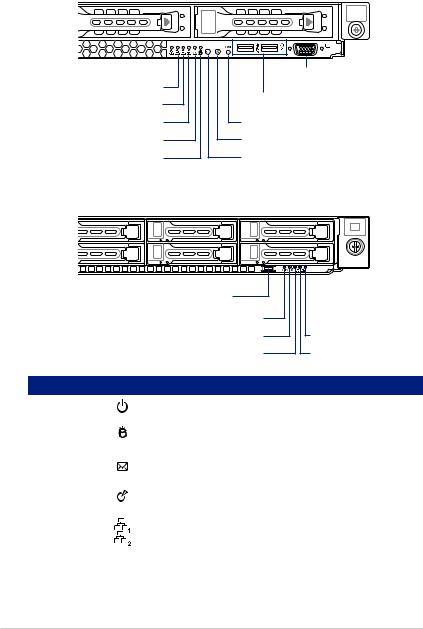
1.7 LED
1.7.1
RS500A-E10-RS4 / RS500A-E10-PS4
4 |
3 |
2 |
1 |
4  321
321
USB 3.0
Reset Location
RS500A-E10-RS12U
|
|
|
Location |
1
2
LED |
|
|
|
|
|
|
|
|
|
|
|
|
|
|
|
|
|
|
/ |
|
|
|
|
|
|
|
|
|
|
|
|
|
|
||
Location |
|
|
|
|
|
|
Location |
|
|
|
|
|
|
|
|
|
|
|
|
|
|
|
|
1-10
1.7.2
|
|
|
|
ACT/LINK SPEED |
||||||
Activity/Link LED |
|
Speed LED |
||||||||
|
LED LED |
|||||||||
|
|
|
|
|
|
|
|
|
|
|
|
|
|
10 Mbps |
|
|
|
|
|
|
|
|
|
|
|
|
|
|
||||
|
|
|
|
|
|
|
||||
|
|
|
100 Mbps |
|
|
|
|
|
|
|
|
|
|
|
|
|
|
||||
|
|
|
1 Gbps |
|
|
|
|
|
|
|
|
|
|||||||||
|
|
|
|
|
||||||
DM_LAN1
|
|
|
|
ACT/LINK SPEED |
Activity/Link LED |
|
Speed LED |
LED LED |
|
|
|
|
|
|
|
|
|
10 Mbps |
|
|
|
|
100 Mbps |
|
|
|
|
1 Gbps |
DM |
1.7.3
RS500A-E10-RS4 / RS500A-E10-PS4 RS500A-E10-RS12U
|
|
|
|
|
|
|
|
|
|
|
|
|
|
|
|
|
|
|||
|
|
|
|
|
|
|
|
|
|
|
|
|
|
|
|
|
|
|
|
|
|
|
|
|
|
|
|
|
|
|
|
|||
|
|
|
|
|
|
|
|
|
|
RAID |
|||
|
|
|
|
|
||
|
|
|
|
|
|
|
|
|
|
|
|
|
|
|
/ |
|
RAID |
|
|
|
|
|
|
|
|
|
|
|
/ |
|
RAID Locating |
|
|
|
|
|
|
|
|
|
|
|
/ |
|
|
|
|
|
|
|
|
|
|
|
|
|
|
|
/ |
|||
|
|
|
|
|
|
|
RS500A-E10 1-11

1.7.4 Q-Code
Action |
PHASE |
POST CODE |
TYPE |
DESCRIPTION |
|
|
|
0x01 |
Progress |
First post code |
|
|
|
0x02 |
Progress |
Load BSP microcode |
|
SEC Start up |
Security Phase |
0x03 |
Progress |
Perform early platform Initialization |
|
0x04 |
Progress |
Set cache as ram for PEI phase |
|||
|
|
||||
|
|
0x05 |
Progress |
Establish Stack |
|
|
|
0x06 |
Progress |
CPU Early Initialization |
|
|
|
0x00 |
Error |
General - Success |
|
|
|
0x01 |
Error |
Generic Error Code |
|
|
|
0x02 |
Error |
Generic Memory Error |
|
|
|
0x03 |
Error |
Buffer Overflow |
|
|
|
0x04 |
Error |
Invalid Parameter(s) |
|
|
|
0x05 |
Error |
Invalid Data Length |
|
|
|
0x06 |
Error |
Data Alignment Error |
|
|
|
0x07 |
Error |
Null Pointer Error |
|
|
|
0x08 |
Error |
Unsupported Function |
|
|
|
0x09 |
Error |
Invalid Service ID |
|
|
|
0x0A |
Error |
Invalid Address |
|
|
|
0x0B |
Error |
Out of Resource Error |
|
|
|
0x0C |
Error |
Timeout |
|
|
|
0x0D |
Error |
data abort exception |
|
|
|
0x0E |
Error |
prefetch abort exception |
|
|
|
0x0F |
Error |
Out of Boundary Condition Reached |
|
|
|
0x10 |
Error |
Data corruption |
|
|
|
0x11 |
Error |
Invalid command |
|
|
|
0x12 |
Error |
The package type provided by BR is incorrect |
|
|
|
0x13 |
Error |
Failed to retrieve FW header during FW validation |
|
|
|
0x14 |
Error |
Key size not supported |
|
|
|
0x15 |
Error |
Agesa0 verification error |
|
|
|
0x16 |
Error |
SMU FW verification error |
|
|
|
0x17 |
Error |
OEM SINGING KEY verification error |
|
|
|
0x18 |
Error |
Generic FW Validation error |
|
|
|
0x19 |
Error |
RSA operation fail - bootloader |
|
|
|
0x1A |
Error |
CCP Passthrough operation failed - internal status |
|
|
PSP Boot Loader |
0x1B |
Error |
AES operation fail |
|
PSP Boot |
phase (Error Post |
0x1C |
Error |
CCP state save failed |
|
|
Codes) |
0x1D |
Error |
CCP state restore failed |
|
|
|
||||
|
|
0x1E |
Error |
SHA256 operation fail - internal status |
|
|
|
0x1F |
Error |
ZLib Decompression operation fail |
|
|
|
0x20 |
Error |
HMAC-SHA256 operation fail - internal status |
|
|
|
0x21 |
Error |
Booted from boot source not recognized by PSP |
|
|
|
0x22 |
Error |
PSP directory entry not found |
|
|
|
0x23 |
Error |
PSP failed to set the write enable latch |
|
|
|
0x24 |
Error |
PSP timed out because spirom took too long |
|
|
|
0x25 |
Error |
Cannot find BIOS directory |
|
|
|
0x26 |
Error |
SpiRom is not valid |
|
|
|
0x27 |
Error |
slave die has different security state from master |
|
|
|
0x28 |
Error |
SMI interface init failure |
|
|
|
0x29 |
Error |
SMI interface generic error |
|
|
|
0x2A |
Error |
invalid die ID executes MCM related function |
|
|
|
0x2B |
Error |
invalid MCM configuration table read from bootrom |
|
|
|
0x2C |
Error |
Valid boot mode wasn't detected |
|
|
|
0x2D |
Error |
NVStorage init failure |
|
|
|
0x2E |
Error |
NVStorage generic error |
|
|
|
0x2F |
Error |
MCM 'error' to indicate slave has more data to send |
|
|
|
0x30 |
Error |
MCM error if data size exceeds 32B |
|
|
|
0x31 |
Error |
Invalid client id for SVC MCM call |
|
|
|
0x32 |
Error |
MCM slave status register contains bad bits |
|
|
|
0x33 |
Error |
MCM call was made in a single die environment |
|
|
|
0x34 |
Error |
PSP secure mapped to invalid segment (should be 0x400_0000) |
|
|
|
0x35 |
Error |
No physical x86 cores were found on die |
|
|
|
0x36 |
Error |
Insufficient space for secure OS (range of free SRAM to SVC stack base) |
|
|
|
0x37 |
Error |
SYSHUB mapping memory target type is not supported |
|
|
|
0x38 |
Error |
Attempt to unmap permanently mapped TLB to PSP secure region |
1-12

Action |
PHASE |
POST CODE |
TYPE |
DESCRIPTION |
|
|
0x39 |
Error |
Unable to map an SMN address to AXI space |
|
|
0x3A |
Error |
Unable to map a SYSHUB address to AXI space |
|
|
0x3B |
Error |
The count of CCXs or cores provided by bootrom is not consistent |
|
|
0x3C |
Error |
Uncompressed image size doesn't match value in compressed header |
|
|
0x3D |
Error |
Compressed option used in case where not supported |
|
|
0x3E |
Error |
Fuse info on all dies don't match |
|
|
0x3F |
Error |
PSP sent message to SMU; SMU reported an error |
|
|
0x40 |
Error |
Function RunPostX86ReleaseUnitTests failed in memcmp() |
|
|
0x41 |
Error |
Interface between PSP to SMU not available. |
|
|
0x42 |
Error |
Timer wait parameter too large |
|
|
0x43 |
Error |
Test harness module reported an error |
|
|
0x44 |
Error |
x86 wrote C2PMSG_0 interrupting PSP |
|
|
0x45 |
Error |
A write to an L3 register failed |
|
|
0x46 |
Error |
Mini-BL |
|
|
0x47 |
Error |
Mini-BL CCP HMAC Unit-test failed |
|
|
0x48 |
Error |
Potential stack corruption in jump to Mini BL |
|
|
0x49 |
Error |
Error in Validate and Loading AGESA APOB SVC call |
|
|
0x4A |
Error |
Correct fuse bits for DIAG_BL loading not set |
|
|
0x4B |
Error |
The UmcProgramKeys() function was not called by AGESA |
|
|
0x4C |
Error |
Secure unlock error |
|
|
0x4D |
Error |
Syshub register programming mismatch during readback |
|
|
0x4E |
Error |
Family ID in MP0_SFUSE_SEC[7:3] not correct |
|
|
0x4F |
Error |
An operation was invoked that can only be performed by the GM |
|
|
0x50 |
Error |
Failed to acquire host controller semaphore to claim ownership of SMB |
|
|
0x51 |
Error |
Timed out waiting for host to complete pending transactions |
|
|
0x52 |
Error |
Timed out waiting for slave to complete pending transactions |
|
|
0x53 |
Error |
Unable to kill current transaction on host |
|
|
0x54 |
Error |
One of: Illegal command |
|
|
0x55 |
Error |
An SMBus transaction collision detected |
|
|
0x56 |
Error |
Transaction failed to be started or processed by host |
|
|
0x57 |
Error |
An unsolicited SMBus interrupt was received |
|
PSP Boot Loader |
0x58 |
Error |
An attempt to send an unsupported PSP-SMU message was made |
PSP Boot |
phase (Error Post |
0x59 |
Error |
An error/data corruption detected on response from SMU for sent msg |
|
Codes) |
|||
|
0x5A |
Error |
MCM Steady-state unit test failed |
|
|
|
|||
|
|
0x5B |
Error |
S3 Enter failed |
|
|
0x5C |
Error |
AGESA BL did not set PSP SMU reserved addresses via SVC call |
|
|
0x5E |
Error |
CcxSecBisiEn not set in fuse RAM |
|
|
0x5F |
Error |
Received an unexpected result |
|
|
0x60 |
Error |
VMG Storage Init failed |
|
|
0x61 |
Error |
Failure in mbedTLS user app |
|
|
0x62 |
Error |
An error occurred whilst attempting to SMN map a fuse register |
|
|
0x63 |
Error |
Fuse burn sequence/operation failed due to internal SOC error |
|
|
0x64 |
Error |
Fuse sense operation timed out |
|
|
0x65 |
Error |
Fuse burn sequence/operation timed out waiting for burn done |
|
|
0x66 |
Error |
Failure status indicating that the given SecureOS has been |
|
|
0x67 |
Error |
This PSP FW was revoked |
|
|
0x68 |
Error |
The platform model/vendor id fuse is not matching the BIOS public key |
|
|
token |
||
|
|
|
|
|
|
|
0x69 |
Error |
The BIOS OEM public key of the BIOS was revoked for this platform |
|
|
0x6A |
Error |
PSP level 2 directory not match expected value. |
|
|
0x6B |
Error |
BIOS level 2 directory not match expected value. |
|
|
0x6C |
Error |
HVB validation failure for BIOS RTM volume (OEM public/signature failed |
|
|
to validate). |
||
|
|
|
|
|
|
|
0x6D |
Error |
Generic error indicating the CCP HAL initialization failed |
|
|
0x94 |
Error |
Knoll failed to idle correctly after being reset |
|
|
0x95 |
Error |
Bad status returned by I2CKnollCheck |
|
|
0x96 |
Error |
NACK to general call (no device on Knoll I2C bus) |
|
|
0x97 |
Error |
Null pointer passed to I2CKnollCheck |
|
|
0x98 |
Error |
Invalid device-ID found during Knoll authentication |
|
|
0x99 |
Error |
Error during Knoll/Prom key derivation |
|
|
0x9A |
Error |
Null pointer passed to Crypto function |
|
|
0x9B |
Error |
Error in checksum from wrapped Knoll/Prom keys |
|
|
0x9C |
Error |
Knoll returned an invalid response to a command |
|
|
0x9D |
Error |
Bootloader failed in Knoll Send Command function |
|
|
0x9E |
Error |
No Knoll device found by verifying MAC |
RS500A-E10 1-13

Action |
PHASE |
POST CODE |
TYPE |
DESCRIPTION |
|
|
0xA0 |
Progress |
Bootloader successfully entered C Main |
|
|
0xA1 |
Progress |
Master initialized C2P / slave waited for master to init C2P |
|
|
0xA2 |
Progress |
HMAC key successfully derived |
|
|
0xA3 |
Progress |
Master got Boot Mode and sent boot mode to all slaves |
|
|
0xA4 |
Progress |
SpiRom successfully initialized |
|
|
0xA5 |
Progress |
BIOS Directory successfully read from SPI to SRAM |
|
|
0xA6 |
Progress |
Early unlock check |
|
|
0xA7 |
Progress |
Inline Aes key successfully derived |
|
|
0xA8 |
Progress |
Inline-AES key programming is done |
|
|
0xA9 |
Progress |
Inline-AES key wrapper derivation is done |
|
|
0xAA |
Progress |
Bootloader successfully loaded HW IP configuration values |
|
|
0xAB |
Progress |
Bootloader successfully programmed MBAT table |
|
|
0xAC |
Progress |
Bootloader successfully loaded SMU FW |
|
|
0xAD |
Progress |
PSP and SMU configured WAFL |
|
|
0xAE |
Progress |
User mode test harness completed successfully |
|
|
0xAF |
Progress |
Bootloader loaded Agesa0 from SpiRom |
|
|
0xB0 |
Progress |
AGESA phase has completed |
|
|
0xB1 |
Progress |
RunPostDramTrainingTests() completed successfully |
|
|
0xB2 |
Progress |
SMU FW Successfully loaded to SMU Secure DRAM |
|
|
0xB3 |
Progress |
Sent all required boot time messages to SMU |
|
|
0xB4 |
Progress |
Validated and ran Security Gasket binary |
|
|
0xB5 |
Progress |
UMC Keys generated and programmed |
|
|
0xB6 |
Progress |
Inline AES key wrapper stored in DRAM |
|
|
0xB7 |
Progress |
Completed FW Validation step |
|
|
0xB8 |
Progress |
Completed FW Validation step |
|
|
0xB9 |
Progress |
BIOS copy from SPI to DRAM complete |
|
|
0xBA |
Progress |
Completed FW Validation step |
|
PSP Boot Loader |
0xBB |
Progress |
BIOS load process fully complete |
|
0xBC |
Progress |
Bootloader successfully release x86 |
|
PSP Boot |
phase (Status Post |
0xBD |
Progress |
Early Secure Debug completed |
|
Codes) |
|||
|
|
0xBE |
Progress |
GetFWVersion command received from BIOS is completed |
|
|
0xBF |
Progress |
SMIInfo command received from BIOS is completed |
|
|
0xC0 |
Progress |
Successfully entered WarmBootResume() |
|
|
0xC1 |
Progress |
Successfully copied SecureOS image to SRAM |
|
|
0xC2 |
Progress |
Successfully copied trustlets to PSP Secure Memory |
|
|
0xC3 |
Progress |
About to jump to Secure OS (SBL about to copy and jump) |
|
|
0xC4 |
Progress |
Successfully restored CCP and UMC state on S3 resume |
|
|
0xC5 |
Progress |
PSP SRAM HMAC validated by Mini BL |
|
|
0xC6 |
Progress |
About to jump to <t-base in Mini BL |
|
|
0xC7 |
Progress |
VMG ECDH unit test started |
|
|
0xC8 |
Progress |
VMG ECDH unit test passed |
|
|
0xC9 |
Progress |
VMG ECC CDH primitive unit test started |
|
|
0xCA |
Progress |
VMG ECC CDH primitive unit test passed |
|
|
0xCB |
Progress |
VMG SP800-108 KDF-CTR HMAC unit test started |
|
|
0xCC |
Progress |
VMG SP800-108 KDF-CTR HMAC unit test passed |
|
|
0xCD |
Progress |
VMG LAUNCH_* test started |
|
|
0xCE |
Progress |
VMG LAUNCH_* test passed |
|
|
0xCF |
Progress |
MP1 has been taken out of reset |
|
|
0xD0 |
Progress |
PSP and SMU Reserved Addresses correct |
|
|
0xD1 |
Progress |
Reached Naples steady-state WFI loop |
|
|
0xD2 |
Progress |
Knoll device successfully initialized |
|
|
0xD3 |
Progress |
32-byte RandOut successfully returned from Knoll |
|
|
0xD4 |
Progress |
32-byte MAC successfully received from Knoll. |
|
|
0xD5 |
Progress |
Knoll device verified successfully |
|
|
0xD6 |
Progress |
Done enabling power for Knoll |
|
|
0xD7 |
Progress |
Enter recovery mode due to trustlet validation fail. |
|
|
0xD8 |
Progress |
Enter recovery mode due to OS validation fail. |
|
|
0xD9 |
Progress |
Enter recovery mode due to OEM public key not found. |
1-14

Action |
PHASE |
POST CODE |
TYPE |
DESCRIPTION |
|
|
|
0x10 |
Progress |
PEI Core Entry |
|
|
PEI(Pre-EFI |
0x11 |
Progress |
PEI cache as ram CPU initial |
|
|
Initialization) phase |
0x15 |
Progress |
NB Initialization before installed memory |
|
|
|
0x19 |
Progress |
SB Initialization before installed memory |
|
|
|
0x32 |
Progress |
CPU POST-Memory Initialization |
|
|
|
0x33 |
Progress |
CPU Cache Initialization |
|
|
|
0x34 |
Progress |
Application Processor(s) (AP) Initialization |
|
|
|
0x35 |
Progress |
BSP Selection |
|
|
|
0x36 |
Progress |
CPU Initialization |
|
|
|
0x37 |
Progress |
Pre-memory NB Initialization |
|
|
|
0x3B |
Progress |
Pre-memory SB Initialization |
|
|
|
0x4F |
Progress |
DXE Initial Program Load(IPL) |
|
Quick VGA |
|
0x60 |
Progress |
DXE Core Started |
|
|
DXE(Driver |
0x61 |
Progress |
DXE NVRAM Initialization |
|
|
Execution |
0x62 |
Progress |
SB run-time Initialization |
|
|
Environment) |
||||
|
phase |
0x63 |
Progress |
CPU DXE Initialization |
|
|
|
0x68 |
Progress |
PCI HB Initialization |
|
|
|
0x69 |
Progress |
NB DXE Initialization |
|
|
|
0x6A |
Progress |
NB DXE SMM Initialization |
|
|
|
0x70 |
Progress |
SB DXE Initialization |
|
|
|
0x71 |
Progress |
SB DXE SMM Initialization |
|
|
|
0x72 |
Progress |
SB DEVICES Initialization |
|
|
|
0x78 |
Progress |
ACPI Module Initialization |
|
|
|
0x79 |
Progress |
CSM Initialization |
|
|
|
0xD0 |
Progress |
CPU PM Structure Initialization |
|
|
|
0x90 |
Progress |
BDS started |
|
|
|
0x91 |
Progress |
Connect device event |
|
|
|
0x92 |
Progress |
PCI Bus Enumeration |
|
|
|
0x93 |
Progress |
PCI Bus Enumeration |
|
|
|
0x94 |
Progress |
PCI Bus Enumeration |
|
|
|
0x95 |
Progress |
PCI Bus Enumeration |
|
|
|
0x96 |
Progress |
PCI Bus Enumeration |
|
|
|
0x97 |
Progress |
Console output connect event |
|
|
|
0x98 |
Progress |
Console input connect event |
|
|
|
0x99 |
Progress |
AMI Super IO start |
|
|
|
0x9A |
Progress |
AMI USB Driver Initialization |
|
|
|
0x9B |
Progress |
AMI USB Driver Initialization |
|
|
|
0x9C |
Progress |
AMI USB Driver Initialization |
|
|
BDS(Boot Device |
0x9D |
Progress |
AMI USB Driver Initialization |
|
|
0xb2 |
Progress |
Legacy Option ROM Initialization |
||
|
Selection) phase |
||||
Normal boot |
0xb3 |
Progress |
Reset system |
||
|
|||||
|
|
0xb4 |
Progress |
USB hotplug |
|
|
|
0xb6 |
Progress |
NVRAM clean up |
|
|
|
0xb7 |
Progress |
NVRAM configuration reset |
|
|
|
0xA0 |
Progress |
IDE, AHCI Initialization |
|
|
|
0xA1 |
Progress |
IDE, AHCI Initialization |
|
|
|
0xA2 |
Progress |
IDE, AHCI Initialization |
|
|
|
0xA3 |
Progress |
IDE, AHCI Initialization |
|
|
|
0x00~0xFF |
Progress |
Wait BMC ready |
|
|
|
0xA8 |
Progress |
BIOS Setup Utility password verify |
|
|
|
0xA9 |
Progress |
BIOS Setup Utility start |
|
|
|
0xAB |
Progress |
BIOS Setup Utility input wait |
|
|
|
0xAD |
Progress |
Ready to boot event |
|
|
|
0xAE |
Progress |
Legacy boot event |
|
|
Operating system |
0xAA |
Progress |
APIC mode |
|
|
phase |
0xAC |
Progress |
PIC mode |
RS500A-E10 1-15

1-16
2
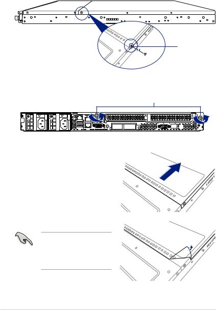
2.1
2.1.1
1.
2.
3. 上蓋前緣與前半部上蓋保留約半吋距
4.
5. 1 4
免啟動後系統無法正常散熱 而導致過熱。
2-2

2.2 CPU
Socket SP3 AMD EPYC™ 7002 & 7003
•PnP
• 在Socket SP3 Return Merchandise Authorization RMA
RS500A-E10 2-3

3.
4.
5.
2-4
Loading...