


T761
ASKO
USE AND CARE GUIDE
omom
om
omom
tingting
ting
ANT!ANT!
ANT!
ANT!ANT!
TT
T
TT
IMPORIMPOR
IMPOR
IMPORIMPOR
ead all operead all oper
ead all oper
ead all operead all oper
r r
r
r r
,,
,
,,
erer
er
et the best perfet the best perf
et the best perf
et the best perfet the best perf
o go g
o g
o go g
TT
T
TT
our drour dr
our dr
our drour dr
yy
y
yy
instructions before using it forinstructions before using it for
instructions before using it for
instructions before using it forinstructions before using it for
the first time.the first time.
the first time.
the first time.the first time.
erer
yy
y
yy
mance frmance fr
mance fr
mance frmance fr
oror
or
oror
tingting
aa
a
aa
DRYER
ENGLISHENGLISH
ENGLISHENGLISH
ENGLISH
ENGLISHENGLISH
ENGLISHENGLISH
ENGLISH
ÇAISÇAIS
ÇAISÇAIS
ÇAIS
FRANFRAN
FRANFRAN
FRAN
CONTENTS
IMPORTANT SAFETY INSTRUCTIONS 2
SAFETY FEATURES 2
ASKO DRYER FEATURES 3
ENERGY SAVING TIPS 3
INSTALLATION INSTRUCTIONS 4
PREPARING THE LAUNDRY 9
T701 OPERATING INSTRUCTIONS 11
T721 OPERATING INSTRUCTIONS 12
T761 AND T781 OPERATING INSTRUCTIONS 13
CARE AND MAINTENANCE INSTRUCTIONS 18
TROUBLESHOOTING 20
PRODUCT WARRANTY 23
INDEX 24
SAVE THESE INSTRUCTIONS FOR FUTURE REFERENCE
Page 1
AÑOLAÑOL
AÑOLAÑOL
AÑOL
ESPESP
ESPESP
ESP

IMPORIMPOR
IMPOR
IMPORIMPOR
TT
ANT SAFETY INSTRANT SAFETY INSTR
T
ANT SAFETY INSTR
TT
ANT SAFETY INSTRANT SAFETY INSTR
UCTIONSUCTIONS
UCTIONS
UCTIONSUCTIONS
To reduce the risk of fire, electric shock, or injury to
persons when using your appliance, follow basic
precautions, including the following:
♦ Electrical installation, if required, must be done by
a licensed electrician.
♦ Read all instructions before using the appliance.
♦ Do not allow children to play on or in the appliance.
Close supervision of children is necessary when
the appliance is used near children.
♦ Before the appliance is removed from service or
discarded, remove the door to the drying compartment.
♦ Do not reach into the appliance if the drum is moving.
♦ Do not install or store this appliance where it will be
exposed to the weather.
♦ Do not tamper with controls.
♦ Do not use fabric softeners or products to eliminate static
unless the manufacturer gives written assurance that
the product will not damage a tumble dryer.
♦ Do not heat dry items containing:
• vinyl, plastic, foam rubber or similarly textured
rubberlike materials
• fiberglass
• wool unless the label specifies “washable”
♦ Do not heat dry items that have been dry-cleaned at
home.
♦ The dryer is made and marked to facilitate recycling.
When it is no longer useful, contact your local refuse
collection service for advice on how to properly
dispose of the dryer for purposes of recycling.
WARNING!
This appliance must be properly grounded. Improper
connection of the equipment grounding conductor can
result in a risk of electric shock. Check with a qualified
electrician or serviceman if you are in doubt as to
whether the appliance is properly grounded.
The plug must be plugged into an appliance outlet that
is properly installed and grounded in accordance with
all local codes and ordinances.
To reduce the risk of fire, this appliance must be
exhausted outdoors or the equivalent. Do not exhaust
into a chimney, wall, ceiling or concealed space in a
building.
WARNING!
Do not wash or dry articles that have been previously
cleaned in, washed in, soaked in, or spotted with
gasoline, dry-cleaning solvents, cooking oils, other
flammable or explosive substances as they give off
vapors that could ignite or explode.
♦ Clean the lint filter before or after each load.
♦ Keep the area around the exhaust opening and
adjacent areas free from the accumulation of lint,
dust, and dirt.
♦ The interior of the machine and exhaust duct should
be cleaned periodically by an authorized ASKO
service agent.
♦ Do not attempt to repair or replace any part of the
appliance or perform any servicing unless
specifically recommended in this guide.
SAFETY FEASAFETY FEA
SAFETY FEA
SAFETY FEASAFETY FEA
CHILD-SAFE DOOR CACHILD-SAFE DOOR CA
CHILD-SAFE DOOR CA
CHILD-SAFE DOOR CACHILD-SAFE DOOR CA
ASKO dryers have a child-safe magnetic door catch
that allows the door to be easily opened from the inside.
CHILD-SAFE STCHILD-SAFE ST
CHILD-SAFE ST
CHILD-SAFE STCHILD-SAFE ST
You can program Models T761 and T781 not to start
unless the Start button is held down for three seconds.
This is to prevent children from inadvertently starting
the machine. Refer to page 16 for instructions on how
to program this safety feature.
TURESTURES
TURES
TURESTURES
TT
T
TT
ARAR
T FEAT FEA
AR
T FEA
ARAR
T FEAT FEA
CHCH
CH
CHCH
TURETURE
TURE
TURETURE
NOTE: This manual does not cover every possible
condition and situation that may occur. Use
common sense and caution when installing,
operating, and maintaining any appliance.
AUTAUT
OMAOMA
AUT
AUTAUT
A door switch automatically stops the dryer when the
door is opened. The dryer will not start again until you
close the door and press the Start button.
OVERHEAOVERHEA
OVERHEA
OVERHEAOVERHEA
ASKO dryers have an overheat protection switch that
automatically turns off the machine if the temperature
gets too high. Refer to page 3 for more information.
TIC DOOR SWITTIC DOOR SWIT
OMA
TIC DOOR SWIT
OMAOMA
TIC DOOR SWITTIC DOOR SWIT
T PRT PR
T PR
T PRT PR
OO
TECTIONTECTION
O
TECTION
OO
TECTIONTECTION
CHCH
CH
CHCH
Page 2
ASKASK
ASK
ASKASK
O DRO DR
O DR
O DRO DR
YER FEAYER FEA
YER FEA
YER FEAYER FEA
TURESTURES
TURES
TURESTURES
Your new energy-efficient ASKO dryer is designed to
give you maximum drying performance using less
energy. To make the most of the dryer’s functions and
features, we recommend that you read this manual
carefully before using your machine for the first time.
For operating instructions, refer to the section in this
guide for your specific model.
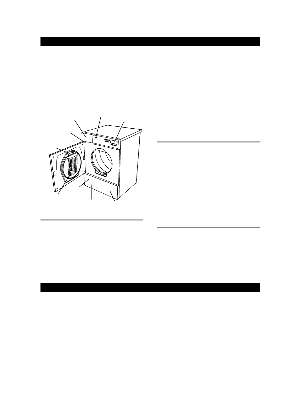
Below is an illustration of the parts and features of your
ASKO dryer.
Condensed Water
Container
(Models T721 & T781)
Type Plate
(Type and Serial
Number)
Lint Filter
Front
y™y™
y™
y™y™
Panel
Cleanable Fan
(behind panel)
STEMSSTEMS
STEMS
STEMSSTEMS
Lint Filter
Holder
DRDR
YING SYYING SY
DR
YING SY
DRDR
YING SYYING SY
ASKO dryers come with three different drying systems:
SensidrSensidr
Sensidr
SensidrSensidr
Models T761 and T781 have our state-of-the-art
Sensidry system. These machines are equipped with
a humidity sensor that ensures different fabrics always
dry thoroughly. This sensor turns off the heat when the
laundry has reached the appropriate dryness.
Power
Button
Control
Panel
Condenser Unit
(behind panel)
Thermostat-ControlThermostat-Control
Thermostat-Control
Thermostat-ControlThermostat-Control
Model T701 has a thermostat that controls the
temperature by turning the heating element on and off
to maintain the selected drying temperature (Normal or
Low) within +/- 5° F.
Timer-ControlTimer-Control
Timer-Control
Timer-ControlTimer-Control
Model T721 offers only timed drying. You can set the
dryer to run from 30 minutes to 190 minutes.
Model T701 has timer-controlled drying in addition to
the two automatic (thermostat-controlled) programs.
When using a timed drying program, be careful not to
leave the clothes in too long. It’s best to use a shorter
time; then if the load isn’t dry , you can set the timer for a
few more minutes.
OO
VERHEAVERHEA
O
VERHEA
OO
VERHEAVERHEA
ASKO dryers are designed with an overheat protection
switch that automatically turns off the machine if the
temperature is too high. The machine will not start until
it has cooled sufficiently.
The dryer could overheat if the lint filter or exhaust hose
becomes clogged with dust. It’s a good idea to make
sure the lint filter and exhaust hose and vent duct are
clean before you call for service.
NOTE: If your dryer overheats frequently, it may not be
vented properly or the room in which it is
located may not have sufficient air circulation.
Contact your installer to have these issues
checked out.
COOL-DOWNCOOL-DOWN
COOL-DOWN
COOL-DOWNCOOL-DOWN
Every program on an ASKO dryer ends with a cool-down
cycle to reduce wrinkling. Unlike with other dryers, the
laundry will feel cool when you remove them from an
ASKO dryer. No more scorched fingertips.
T PRT PR
T PR
T PRT PR
OO
TECTIONTECTION
O
TECTION
OO
TECTIONTECTION
ENGLISHENGLISH
ENGLISHENGLISH
ENGLISH
ENGLISHENGLISH
ENGLISHENGLISH
ENGLISH
ENERENER
ENER
ENERENER
♦ Dry consecutive loads to avoid reheating the dryer.
♦ Do not overload the dryer.
♦ Use the highest spin speeds allowed for the
garments.
♦ Do not put extremely wet clothes into the dryer.
GY SAGY SA
GY SA
GY SAGY SA
VING VING
VING
VING VING
TIPSTIPS
TIPS
TIPSTIPS
♦ Dry like fabrics together (i.e., heavy fabrics together,
light fabrics together).
♦ Clean the lint filter after each load.
♦ Do not over-dry clothes when using the timed program.
♦ Spin the clothes at no less than 800 rpm.
Page 3
INSTINST
INST
INSTINST
ALLAALLA
ALLA
ALLAALLA
TION INSTRTION INSTR
TION INSTR
TION INSTRTION INSTR
UCTIONSUCTIONS
UCTIONS
UCTIONSUCTIONS
Read these instructions carefully and completely before
you install the machine. The installation should be
carried out by a qualified person who is familiar with all
local codes and ordinances for electrical and plumbing
connections.
SPECIFICASPECIFICA
SPECIFICA
SPECIFICASPECIFICA
Height 33-1/2”–34-1/2 (850–876 mm)
Width 23-7/16” (595 mm)
Depth T761/T781: 23-7/16" (595 mm)
Weight 86 lbs (39 kg)
Drum material Stainless Steel
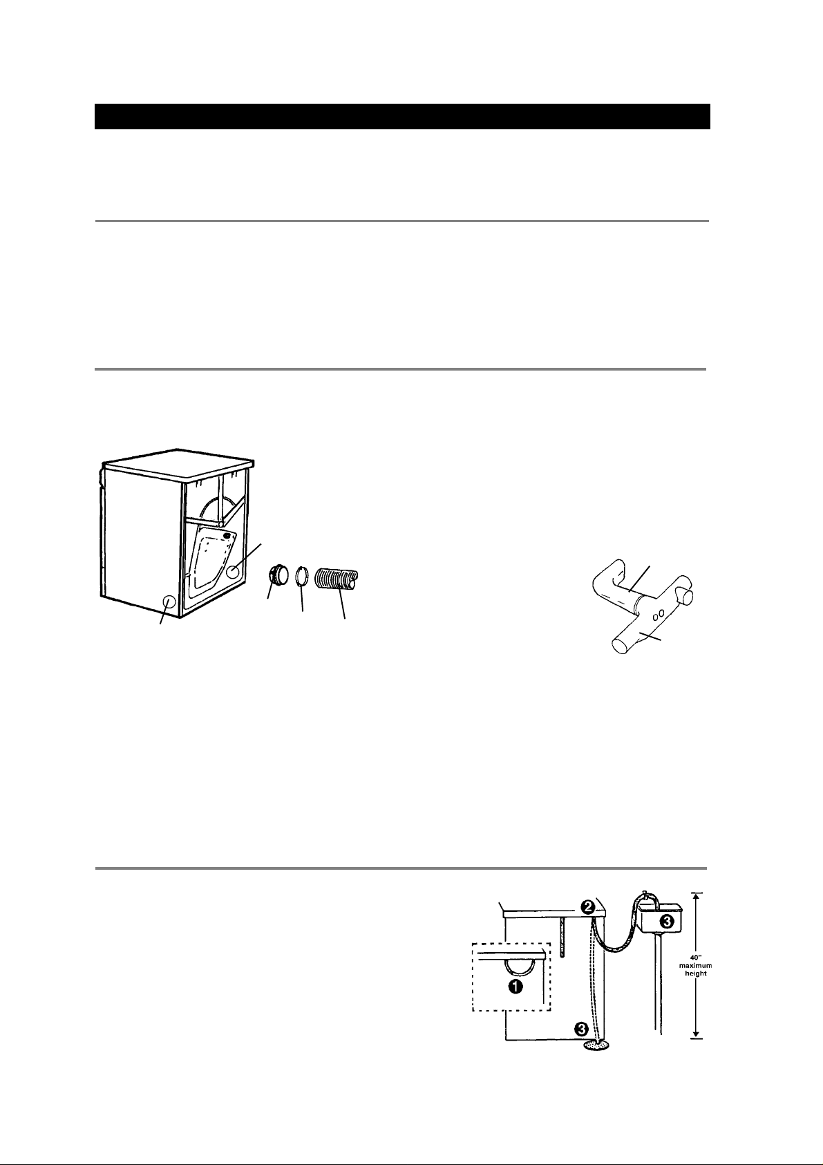
CONNECTING CONNECTING
CONNECTING
CONNECTING CONNECTING
The exhaust hose can be connected at the rear or on
either side of the dryer. When the machine is delivered,
the exhaust outlet at the rear is open.
Side Exhaust Outlet
The dryer is shipped with a stub pipe already installed
on the rear exhaust outlet. The consumer or installer
must purchase a UL-CSA-approved exhaust hose.
RR
ear Outlet Hose Connectionear Outlet Hose Connection
R
ear Outlet Hose Connection
RR
ear Outlet Hose Connectionear Outlet Hose Connection
To connect the exhaust hose to the rear outlet, follow
the steps below:
1. Push the hose onto the stub pipe and secure it with
a clamp.
2. With the hose attached, insert the stub pipe into the
hole. It should snap into place.
TIONSTIONS
TIONS
TIONSTIONS
Plus exhaust hose connection
T701/T721: 24-7/16” (620 mm)
AIR EXHAAIR EXHA
AIR EXHA
AIR EXHAAIR EXHA
The exhaust hose
can be connected at
the rear or on either
side of the dryer.
Rear Exhaust Outlet
Stub
UST (T701 UST (T701
UST (T701
UST (T701 UST (T701
Clamp
Hose
(not supplied)
NOTE: Cosmetic damage must be reported to your
dealer within five days from the date of purchase. After unpacking the dryer, thoroughly
check the unit for cosmetic damage.
Outer casing Stove-enamelled hot-dipped
Power requirement 2800 watts
For connection Single-phase, 230 V, 30 Amp
Internal fuse 15 amp.
Heating element 2500 watts
AND AND
AND
AND AND
NOTE: After you push the dryer into place, check for
CONNECTING THE VENT HOSE TO THE
LEFT OR RIGHT SIDE OUTLET
To connect the exhaust hose to the left or right side
outlet, follow the steps below:
1. Using a flathead screw-
2. Remove the stub pipe from
3. Place the stub pipe in the
4. Follow the instructions for the rear outlet hose
5. Use the exhaust outlet cover you removed from the
WARNING!
To reduce the risk of fire, this appliance must be
exhausted OUTDOORS or the equivalent.
Never cover the end of the dryer stub or vent hose
with anything to catch lint, except for UL approved
vent basket.
T761)T761)
T761)
T761)T761)
kinks in the hose. (Be careful not to use too
much hose, because it could reduce drying
efficiency.)
driver, turn the exhaust
outlet cover to align the tabs
holding the cover in place.
Remove the cover.
the rear exhaust outlet.
outlet you plan to use.
connection.
side to cover the rear exhaust outlet.
galvanized steel
Vent
T-Tube
CONDENSACONDENSA
CONDENSA
CONDENSACONDENSA
If possible, you should install the dryer so the
condensed water will continuously flow into a drain or
sink. To do this, follow the instructions below:
1. Disconnect the short hose (1) from the blue
connection. (It’s okay to let the hose hang down.)
2. Connect the rubber hose supplied with the dryer to
the blue nipple (2).
3. Run the hose to a drain or sink, as illustrated.
NOTE: The drain hose must not be more than 40”
above the floor.
Page 4
TION DRAIN CONNECTION (T721 TION DRAIN CONNECTION (T721
TION DRAIN CONNECTION (T721
TION DRAIN CONNECTION (T721 TION DRAIN CONNECTION (T721
Back of dryer
AND AND
AND
AND AND
T781)T781)
T781)
T781)T781)
CONNECTING CONNECTING
CONNECTING
CONNECTING CONNECTING
TT
T
TT
O O
O
O O
A A
VENTILAVENTILA
A
VENTILA
A A
VENTILAVENTILA
TION DUCT (T701 TION DUCT (T701
TION DUCT (T701
TION DUCT (T701 TION DUCT (T701
AND AND
AND
AND AND
T761)T761)
T761)
T761)T761)
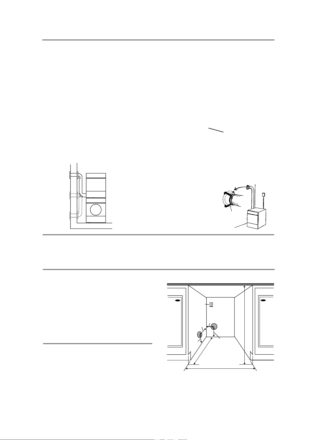
1. Connect the exhaust hose to a ventilation exhaust
fitting or to a discharge through the wall.
2. Secure the hose joint to the outlet stub on the
machine.
3. Run the hose with as few bends as possible to the
point of discharge. If necessary, it can be extended
to a maximum of 20 feet (610 cm) of 4” (10 cm)
diameter ridged pipe.
Make any bends as gentle as possible. A maximum of
four 90° bends may be fitted in the hose. The more
bends and the longer the hose, the less air will circulate
through the machine, which will impede drying
performance. Subtract 4 feet (122 cm) for every 90°
elbow.
NOTE: When installing in warm climates (77° F and
above) with high humidity levels, do not
route the air exhaust hose upwards.
Installation Examples
Subtract 4 feet
(122 cm) for
every 90° elbow.
If more than 20 feet of hose is needed, the diameter
must be increased to 6” or 8” (152 mm or 203 mm).
WARNING!
This appliance should not be exhausted into a
chimney, a wall, a ceiling, or a concealed space of a
building. Only a metal ventilation grill should be used.
If the hose is taken to a wall outlet, a ventilation grill
should be fitted to prevent reverse flow of cold air. Fit the
ventilation grill to the outside or inside of the wall.
Ventilation grill
Make sure nothing is
blocking the ventilation grill.
If there is only one vent duct from the room, a vent spacer
must be fitted.
ENGLISHENGLISH
ENGLISHENGLISH
ENGLISH
ENGLISHENGLISH
ENGLISHENGLISH
ENGLISH
FREESTFREEST
FREEST
FREESTFREEST
The dryer can be placed next to the washing machine.
It is essential that the machine is leveled and the
locknuts are tight to eliminate vibration noise.
BB
UILUIL
B
UIL
BB
UILUIL
ASKO dryers can be installed beneath a cabinet or
worktop with a minimum height of 34” (864 mm). There
must be a gap of about 1/2” (12 mm) all around the
machine, including between the rear edge of the
machine top panel and the back wall. The opening
width must be at least 24-1/2” (622 mm).
Space must also be available for the exhaust hose on
the left, right or rear of the machine. See the diagram for
hole sizes and positions. Note that the hole
measurements are to the center of the hole.
ANDING INSTANDING INST
ANDING INST
ANDING INSTANDING INST
TT
-IN INST-IN INST
T
-IN INST
TT
-IN INST-IN INST
ALLAALLA
ALLA
ALLAALLA
ALLAALLA
ALLA
ALLAALLA
TIONTION
TION
TIONTION
TIONTION
TION
TIONTION
MODELS T721 AND T781
The condensing models work best when they have good
air circulation. Therefore, we don’t recommend they be
installed beneath a cabinet. If it is necessary, however, be
sure to leave a gap of at least 1/2” (12 mm) on all sides.
If you install the dryer so the condensed water will
continuously flow into a drain or sink, you will need a
drain outlet behind the unit. The maximum drain height
is 40” (1016 mm). (See page 4.)
Vent spacer
There should be at least 1/2” (12 mm) of space between
the washer and dryer.
220V, 20 Amp
Single Phase
Outlet
4-1/8"
105 mm
4-23/32"
120 mm
5-1/2"
140 mm
NOTES: The height adjustment for the dryer is
33-1/2” to 34-1/2” (850 mm to 876 mm). Do
not raise it higher than 34-1/2”.
Hole measurements are from center of hole.
"
m
5
2
m
5
3
6
24-1/2" minimum
622 mm
5-1/2"
140 mm
34" to 35"
863 to 889 mm
Page 5
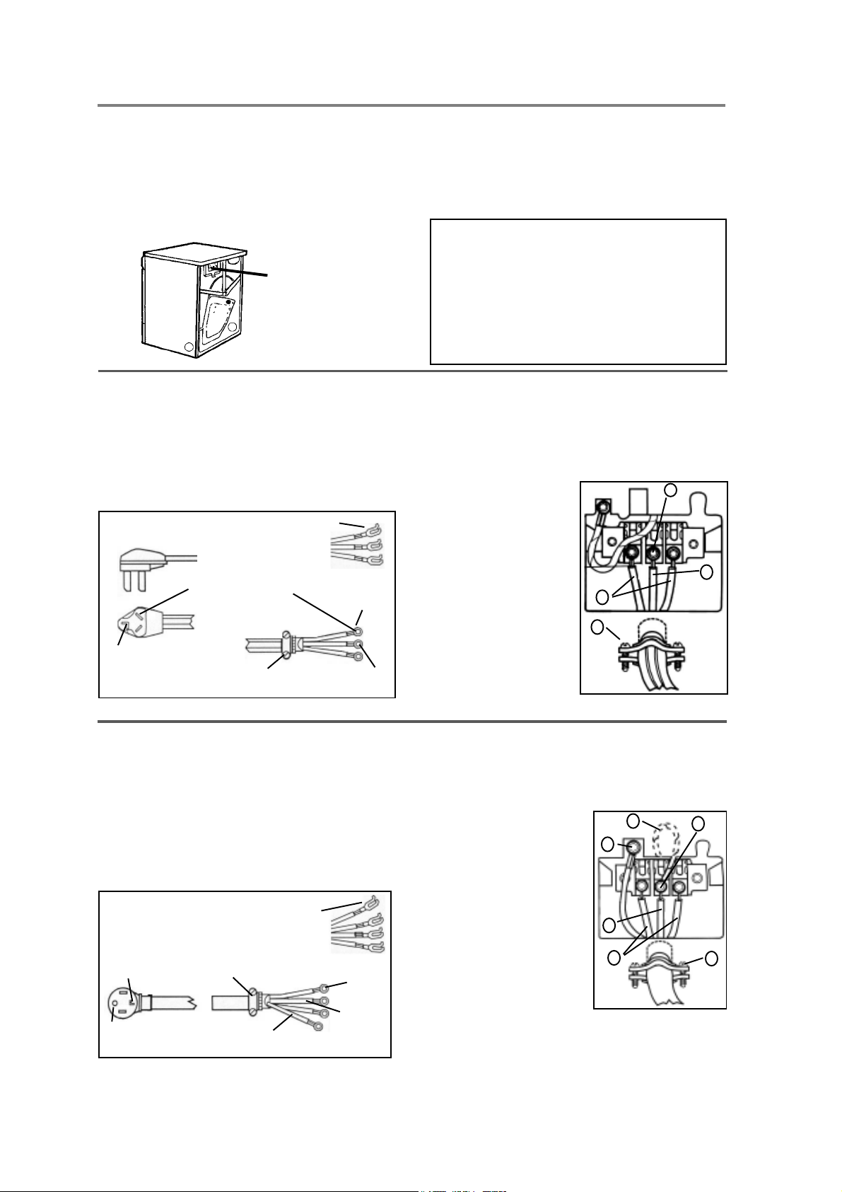
ELECTRICAL CONNECTIONSELECTRICAL CONNECTIONS
ELECTRICAL CONNECTIONS
ELECTRICAL CONNECTIONSELECTRICAL CONNECTIONS
The power supply cord must be grounded. If the
machine is to be used in a wet area, the supply must
be protected by a residual current device.
NOTE: In Canada, the dryer is delivered ready-fitted with
a four-prong plug intended for connection to a singlephase supply.
Remove cover to
access terminal box.
(Requires a 20-Torx
screwdriver.)
Connection to a permanently wired supply point must
be made only by a qualified electrician.
As supplied: Single-phase, 230 V, 60 Hz,
2500 Watt heater rating
30 A fuse required
WARNING:
The receptacle on the rear of the machine is
designed to accommodate ASKO washers ONL Y
(rated 208–240 V .) T o use this receptacle, you must
use the ready-fitted plug supplied with the washing
machine or an equivalent. The supply connection
must be 208–240 V, 20 A.
ASKO washers rated 208–240 V have two internal
fuses of 15 A each.
CONNECTING A 3-WIRE POWER CORD
WARNING!
the power is turned off at the breaker/fuse box.
Before starting this procedure, be sure
Power Supply Cord
You will need a 3-wire power supply cord with three No.
10 copper wires and a matching 3-wire receptacle of
NEMA Type 10-30R, as illustrated below:
3-WIRE CORD
This blade connects
to this conductor.
Neutral
Spade terminals
with upturned
ends
3/4” UL-listed
strain relief
Ring
terminals
Neutral
(white)
CONNECTING A 4-WIRE POWER CORD
WARNING!
the power is turned off at the breaker/fuse box.
Before starting this procedure, be sure
Power Supply Cord
You will need a 4-wire power supply cord with four No.
10 copper wires and a matching 4-wire receptacle of
NEMA Type 14-30R, as illustrated below . The fourth wire
must be identified with a green cover and the neutral
conductor by a white cover.
4-WIRE CORD
Neutral
Ground
prong
Spade terminals
with upturned
ends
3/4” UL-listed
strain relief
Ground
(green)
Ring
terminals
Neutral
(white)
1. Turn the power off at the breaker/fuse box.
2. Remove terminal block cover.
3. Use the strain relief attached below the terminal
block opening.
4. Loosen or remove center terminal block screw.
5. Connect neutral
(white ) wire of power
4
supply cord to the
center, silver-colored
terminal screw.
Tighten screw.
6. Connect the other
wires to outer screws.
7. Tighten the strain relief
screws.
8. Replace terminal box
cover on back of dryer.
6
7
5
9. Plug dryer into wall
receptacle.
10. Turn power on at
breaker/fuse box.
1. Turn the power off at the breaker/fuse box.
2. Remove terminal block cover.
3. Use the strain relief attached below the terminal
block opening.
4. Remove center terminal block screw.
5. Remove ground wire
(green with yellow stripes)
from external ground
connector screw. Fasten
5
6
4
under center, silvercolored terminal block
screw.
6. Connect ground (green)
wire of cord to external
7
ground conductor screw.
7. Connect neutral (white)
wire of cord under center
8
9
screw of terminal block.
8. Connect the other wires
to outer screws.
9. Tighten the strain relief screws.
10. Replace terminal box cover on back of dryer.
11. Plug dryer into wall receptacle.
12. Turn power on at breaker/fuse box.
Page 6
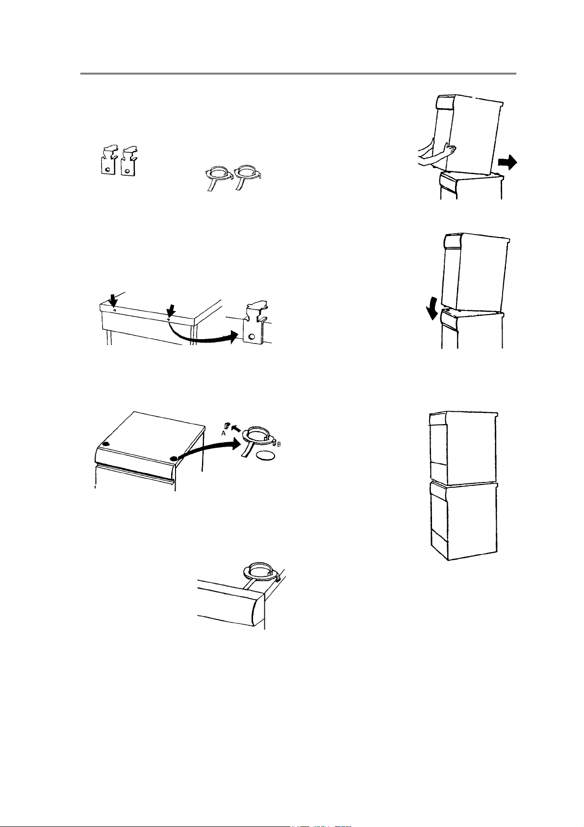
STST
AA
CKED INSTCKED INST
ST
A
CKED INST
STST
AA
CKED INSTCKED INST
ALLAALLA
ALLA
ALLAALLA
TIONTION
TION
TIONTION
ASKO dryers can be mounted on top of any matching
ASKO washer. Mounts are supplied with the machine.
The metal brackets are attached to the lower back of
the unit. The plastic cups are packed inside the dryer.
Two metal brackets for
securing the dryer to
the washer
T o install the dryer on top of the washer, follow the steps
below:
1. Remove the two outside screws (20 torx) from the
back of the washer and use them to secure the metal
brackets, as illustrated.
Washer
back
2. To ensure the dryer is correctly positioned on top of
the washer, align the plastic cups with the front top
edge of the washer.
Two plastic cups to
secure the dryer legs.
Metal brackets
5. Lift the dryer into
position. Raising the
front edge, push the
dryer backwards until it
engages with the
brackets on the back of
the washer.
6. Carefully lower the front
of the dryer, making sure
the feet fit into the plastic
cups.
Stacked InstallationStacked Installation
Stacked Installation
Stacked InstallationStacked Installation
ENGLISHENGLISH
ENGLISHENGLISH
ENGLISH
ENGLISHENGLISH
ENGLISHENGLISH
ENGLISH
Plastic cups
To position the plastic cups, break off the left tab (A)
on the cup to be placed on the right side of the washer
and break off the right tab (B) on the cup to be placed
on the left side of the washer.
3. Remove the protective
paper from the selfadhesive surface
beneath the cups. Being
careful not to press the
adhesive surface against
the top of the washing
machine, use the tabs to
position the cups (as illustrated) then press them
firmly into place.
4. Once the cups are in place, break off the remaining
plastic tabs.
Tumble dryer
Washer
Total height 67”.
Adjustable to 69”.
WARNING!
Never stack a washer on top of a dryer!
Page 7
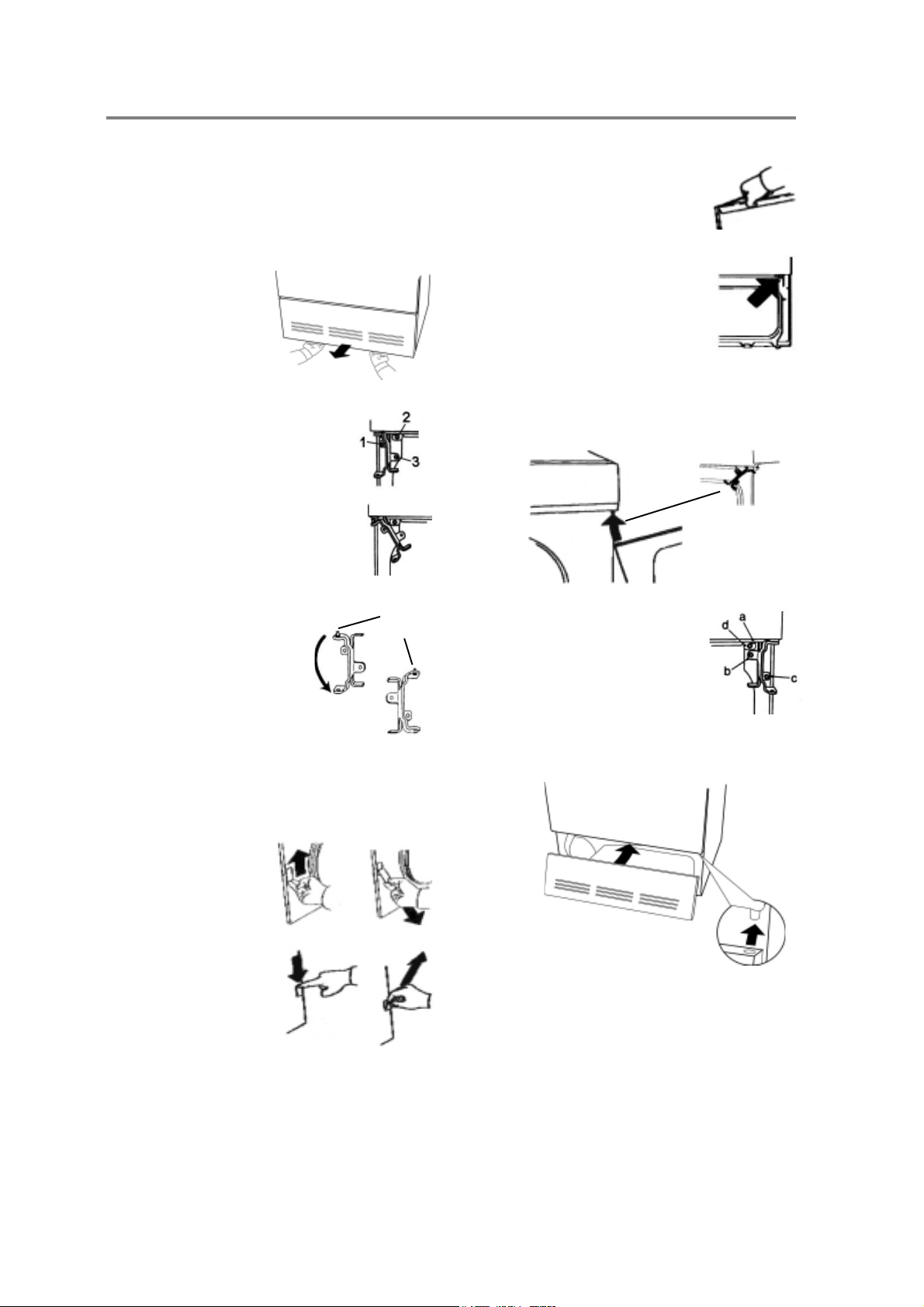
REVERSING THE DOOR HINGESREVERSING THE DOOR HINGES
REVERSING THE DOOR HINGES
REVERSING THE DOOR HINGESREVERSING THE DOOR HINGES
The door hinges on ASKO dryers are reversible. The
dryers are shipped left-hinged. To reverse them, follow
the steps below:
WARNING!
1. Remove the two 20 torx
screws on the bottom
of the front panel then
grasp the bottom of
the panel and pull it
forward and down.
2. Remove the three screws holding
the hinge.
3. Supporting the door from the bottom,
pull it out and to the left as you turn
the hinge counter clockwise.
4. Remove the top hinge pin.
5. Turn the hinge upside down
and put the hinge pin into the
top hole.
6. Repeat steps 2–5 for the
bottom hinge.
7. Loosen the two screws on both outer edges of the
door so you can remove the magnetic door catch
and the cover plate.
Switch off the main power supply
before you start this procedure.
Hinge
pin
12. Using a flathead screwdriver,
carefully remove the plastic plugs
in the upper and lower edge of the
door and place them in the empty
holes on the opposite side.
13. Remove the screw in the top right
corner of the front panel, as
indicated in the illustration. (If you
have a condenser dryer, you will
need to open the condenser
container door.)
14. Now you are ready to mount the door on the right
side. Holding the door at an angle (as illustrated),
fit the hinge pin into the top hole.
15. Replace the screws in the order
illustrated at right (a, b, c).
16. Replace the screw you removed
in step 13 (d).
17. (If the unit has a condenser, close the condenser
door.) Replace the front panel.
8. Remove the magnetic
catch by pushing it up
then lifting it out from the
bottom.
9. Remove the cover plate
on the opposite side of
the door by pushing it
down then lifting it out
from the top.
10. Reverse steps 8 and 9 to place the door catch and
cover plate into their new positions.
11. Tighten the screws on the sides of the doors to
hold the magnetic catch and cover plate in place.
Page 8
18. Turn back on the main power.
 Loading...